Axial force in a rib
Ribs are an integral part of structures. In the past, engineers calculated structures as 2D slabs and ribs were included approximately (as a T section). With the 3D shell models, the ribs can be modelled more accurately as eccentric beams. This article explains the evaluation of internal forces of ribs.
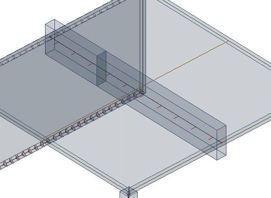
SCIA Engineer integrates the ribs as eccentric beams attached to slabs. The eccentricity E is calculated from the half of the slab thickness D and half of the height of the cross-section of the beam H.
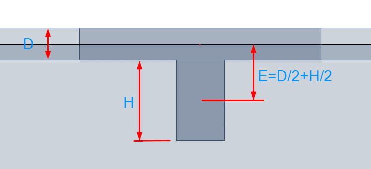
During the input of the cross-section of the beam, the height of the cross-section is defined as a distance between the bottom of the slab and the bottom of the beam. In the picture, the height is marked as “H”.
Due to the shift of the neutral axis, the internal forces in the whole system change. In a simple system subject to a bending moment only, we get a structure with an internal bending moment as well as axial force.
Usually, if the beam is below the slab, we get compression in the slab and tension in the beam.
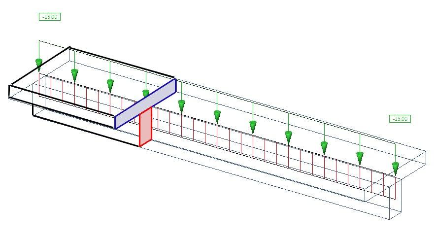
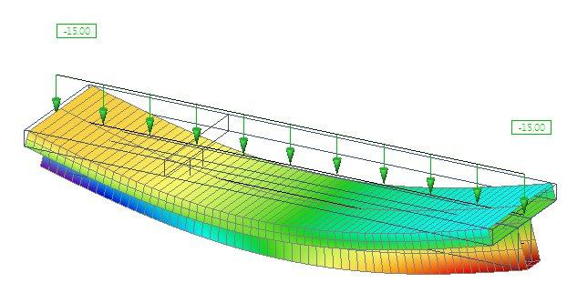
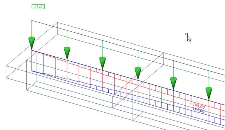
The eccentric beam causes axial forces in the slab. This results from the deformation of the whole slab+beam system. The picture shows the horizontal deformation “ux” to explain graphically the behaviour of the system. This system is composed of two beams of a rectangular cross-section connected by rigid links. The horizontal displacement of the support is free.
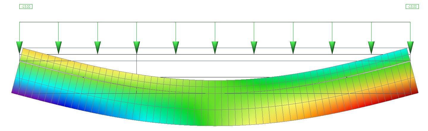
The horizontal deformation in a side view:
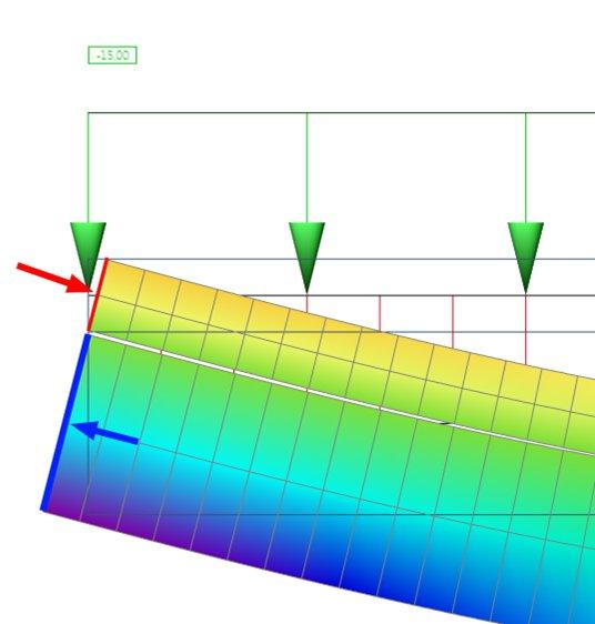
If we look at the beginning of the beam, we can see compression in the slab (red arrow) and tension in the beam (blue arrow).
Of course, the whole system must be in equilibrium and the total axial force (as the sum of the axial force in the slab and the axial force in the beam) must be zero.
In our model, we have only one beam and all the internal forces of the top part are integrated in the axial force in the rib. Practically, the effective width of the rib is smaller than the whole width of the slab. Only exceptionally the ribs are arranged in such a way that there are no gaps between the effective widths, so all internal forces in the slab can be summed up into the rib. This happens if the distance between the ribs is smaller or equal to the effective width of the rib calculated from the national code.
Behaviour of a rib in a wide slab
Now we can investigate a system where the width of the slab is greater than the effective width of the rib. The equilibrium condition must be fulfilled. If we integrate all the axial forces in the whole slab and the beam, we - of course - get a zero result.
We look at the distribution of the axial force in the slab. This is independent on the defined effective width of the slab. Only the stiffnesses of the slab and beam are responsible for the shape of the distribution of internal forces.
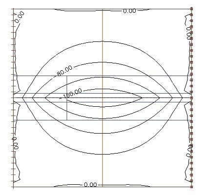
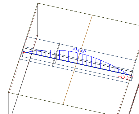
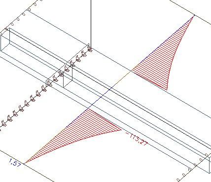
We look at a section across the middle of the slab showing the distribution of the axial force:
We can integrate the axial force in the section across the whole width of the slab. We get a value of 439 kN.
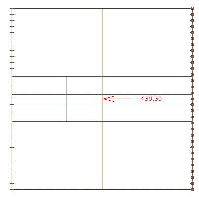
We can compare this value with the axial force in the beam, which is 435 kN. We see the whole system is in equilibrium. The small difference results from the size of the finite elements.
Comparison of different effective widths
However, if we extend the effective width of the rib to the whole width of the slab, we neglect the distribution of the internal forces over the slab and the concentration over the beam (in fact, there are two limit values: the minimum effective width is equal to the width of the beam and the maximum one is equal to the whole width of the slab).
The internal forces in the slab are excluded from the slab and integrated into a new virtual T section. This virtual section consists of the effective slab width and the beam.
We consider the distribution of the axial force in the slab. We can see that this distribution is equal to the one in an earlier picture where the effective width of the rib was defined according to the code.
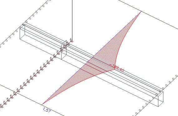
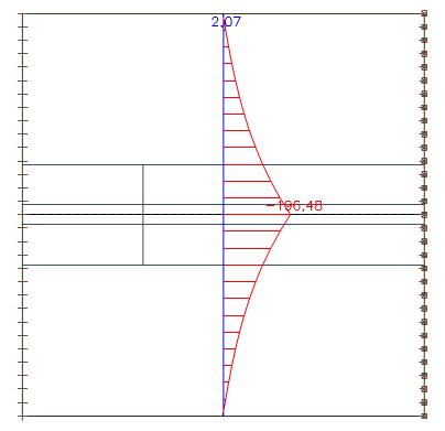
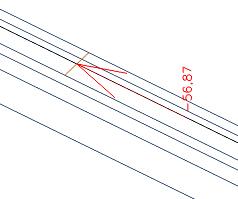
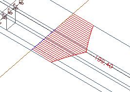
In the picture we can see the axial force after the forces within the effective width of the rib were excluded from the slab. In SCIA Engineer you can achieve this using the checkbox 'Rib' in the results.
These axial forces within the effective width of the slab can be integrated.
We get an axial force equal to 57 kN, which is in the slab. The total axial force in the slab was 435 kN. Therefore, in the part outside the effective width we have as axial force 435 kN - 57 kN = 378 kN.
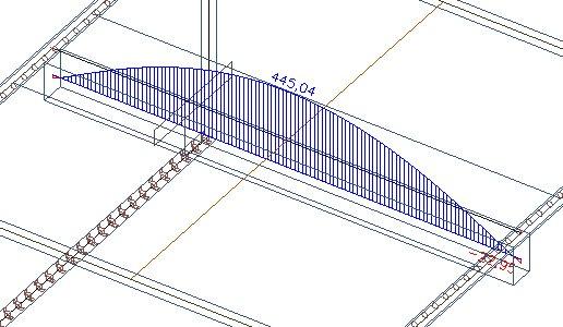
In the beam, we still have the same 445 kN (the difference to the previous pictures results from the changed size of the 2D finite elements).
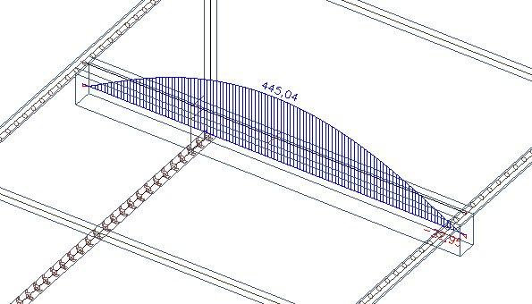
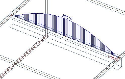
If we create the sum of the integrated axial force in the slab and in the beam, we must get 445 kN - 57 kN = 388 kN.
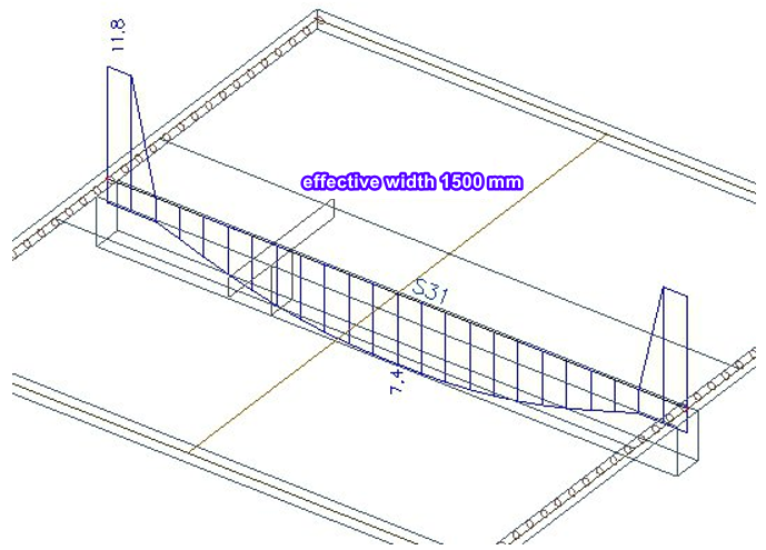
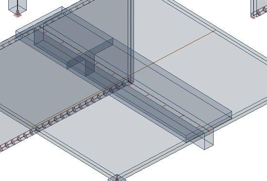
Look what happens if we increase the effective width of the rib to 1500 mm. This results from the following formula: 2 * (0.1 * L) + bw = 2 * 0.6 + 0.3
As we can see, the axial force in the slab is still the same. It must be, because the effective width of the rib has no influence on the distribution of the axial force in the finite element calculation. It only affects the split of the forces after the calculation between the slab and the virtual T section.
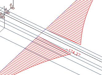
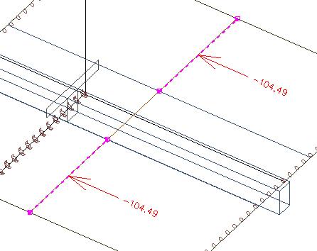
The area of the effective width of the rib will be removed from the slab and the forces will be integrated into the T section. The internal forces outside of the slab will remain in the slab.
These internal forces will be moved to the T section.
If we integrate the axial forces, we get 234 kN.
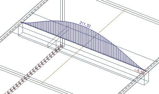
In the rectangular section below the slab we get the original 445 kN.
If we reduce this axial force of the beam by 234 kN, which is the sum of the axial forces from the effective width of the rib, we get 211 kN.
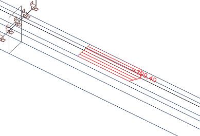
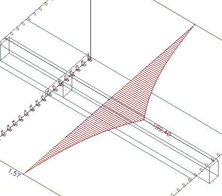
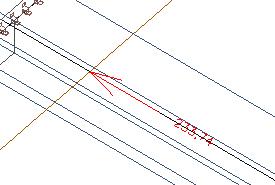
The axial force outside the effective width remains in the slab.
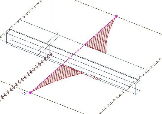
If we integrate the forces (left and right) outside the effective width, we get axial force equal to 210 kN, which is in equilibrium with the tension in the rib as a T Section.
Conclusion
The system must be in equilibrium. In our simplified system consisting of a slab and beam without horizontal forces, we must have zero axial forces as an integration.
The internal forces (in our text we investigated only axial force) will be distributed between the slab and rib. These must be in equilibrium.
The effective width of the rib will be used only for recalculation of the internal forces (N, Vz, My, Mx) between the slab and the virtual T beam. It has no influence on the internal forces in the finite element model.
The sum of the axial forces in the whole slab must be equal to the axial force in the rectangular beam below the slab. If we move only a part of these axial forces within the effective width, some parts of the axial forces remain as compression in the slab outside the effective width (don't worry: these forces will be handled during the design of the reinforcement in the slab). And the unconsidered axial force remains as a tension in the virtual T section of the rib.
There are also other possibilities to model a rib.
You can define a T section without eccentricity. With this kind of modelling, you influence the distribution of the stiffness between the slab and the beam. The definition of the effective width of the rib has a direct influence on the stiffness of the system and on the internal forces. The advantage is that you do not get an axial force in the T section, because there is no eccentricity. On the other hand, you get a little higher self-weight, because the weight of the T section and the slab is doubled. Another disadvantage is that you get reinforcement in the beam and in the slab and you have to mention it in the documentation.
Another option is to define a substitute rectangular section. The principle is that the moment of inertia of the slab+beam system must be the same as for a T section with a rectangular beam and effective width of the rib. From this, you derive the height of the substitute rectangular section (you can find more details in “Günter Rombach: Anwendung der Finite-Elemente-Methode im Betonbau").
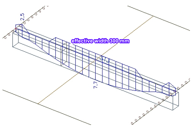
Now we compare the bottom reinforcement in the rib for different effective widths.
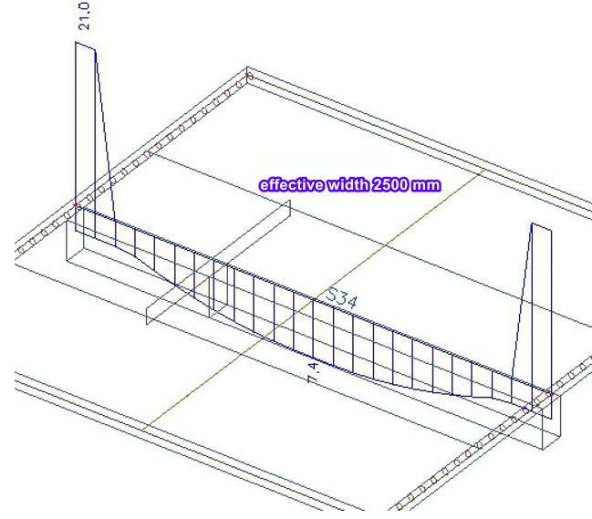
We compare three variants: one with an effective width of 300 mm (the width of the beam), one with a value of 1500 mm (according to EN 1992) and one with a random value of 2500 mm.
Also a shear force influences the result of the longitudinal reinforcement, because a part of the shear force is going to stirrups, a part to the concrete compression strut and a part to the longitudinal reinforcement.