Load panel types
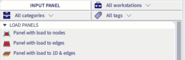
Load panels are entities that are not considered in the FEM analysis. The stiffness is thus not taken into account in the calculation, but they are capable of redistributing the applied surface load to:
- nodes (corners)
- edges (opening edges)
- beams situated in the plane of the panel (beams supporting the panel) and edges
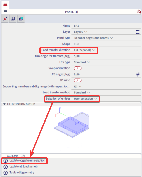
The applied load can be distributed in one or two directions according to the parameter 'Load transfer direction'. The direction is clearly shown using an arrow on the panel. In the defined directions of selected load panel, all entities (nodes, edges, beams) are taken into account or user can edit selection via action button 'Update selection'.
Load to panel nodes
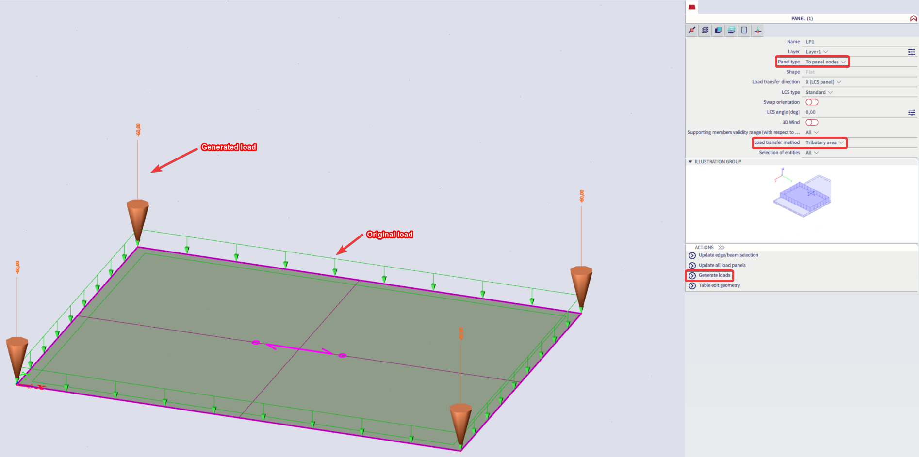
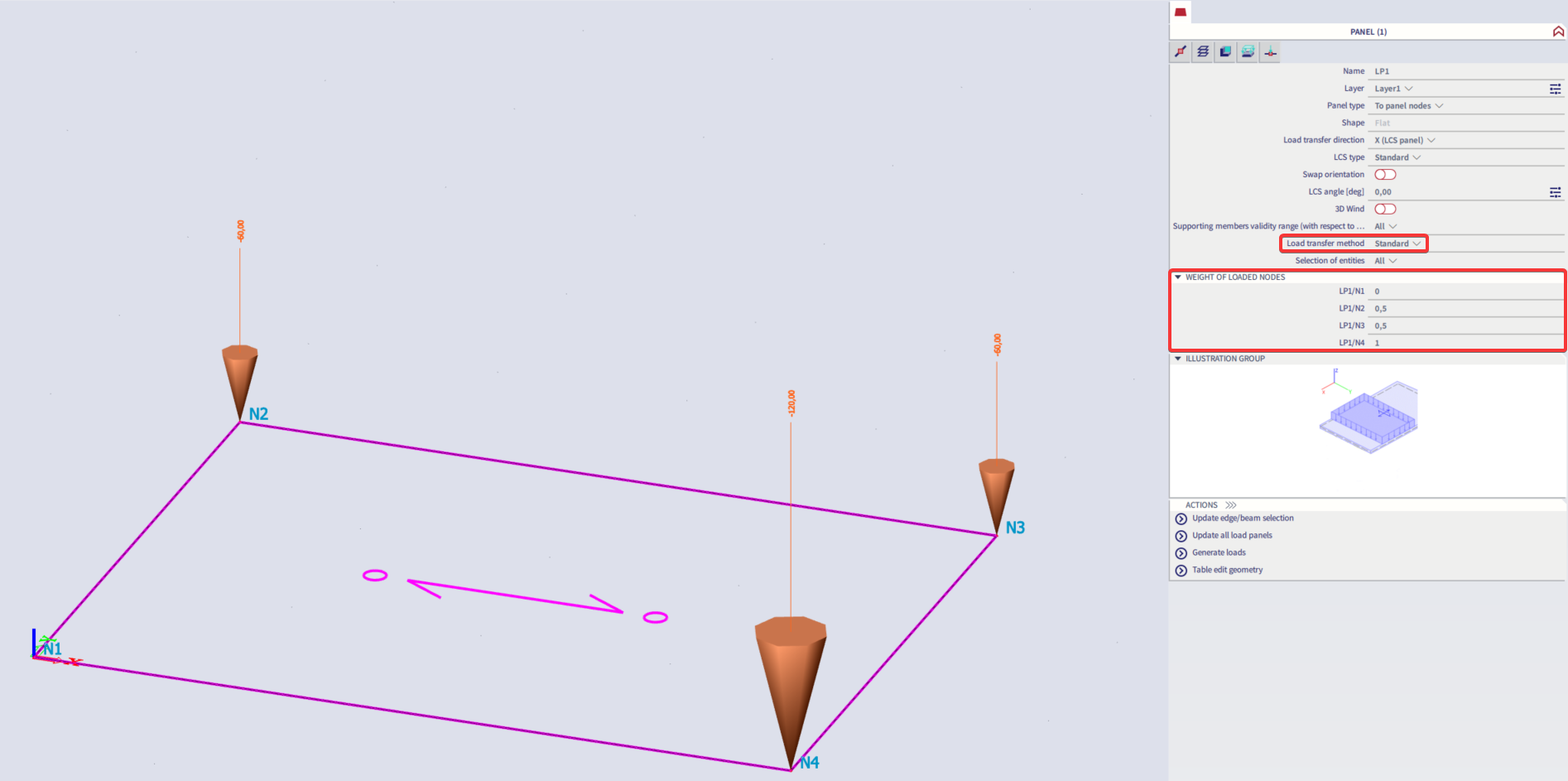
A panel of this type transfers the applied load to all or selected nodes (corners) of the panel. The load is generated only in supported nodes. The total load is distributed to individual nodes according to the length of edges connected to each node.
The panel supports can be displayed. All load types can be used on the panel. The panel is available in all project types - 'Frame', 'Grid', 'General'...
You can set the weight for individual nodes or exclude some of them by using the load transfer method 'Standard' and changing the 'Weight of loaded nodes'.
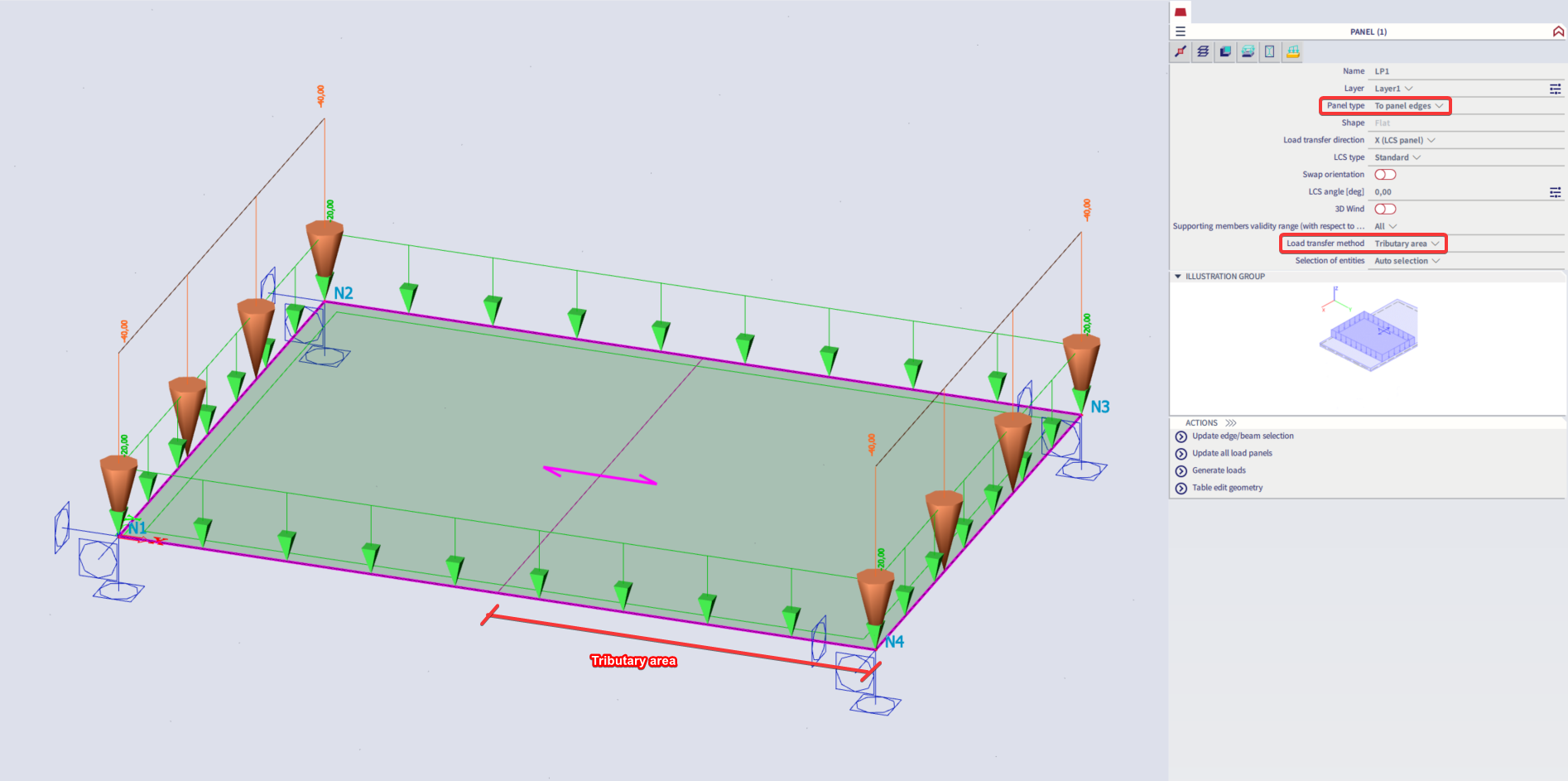
Load to panel edges
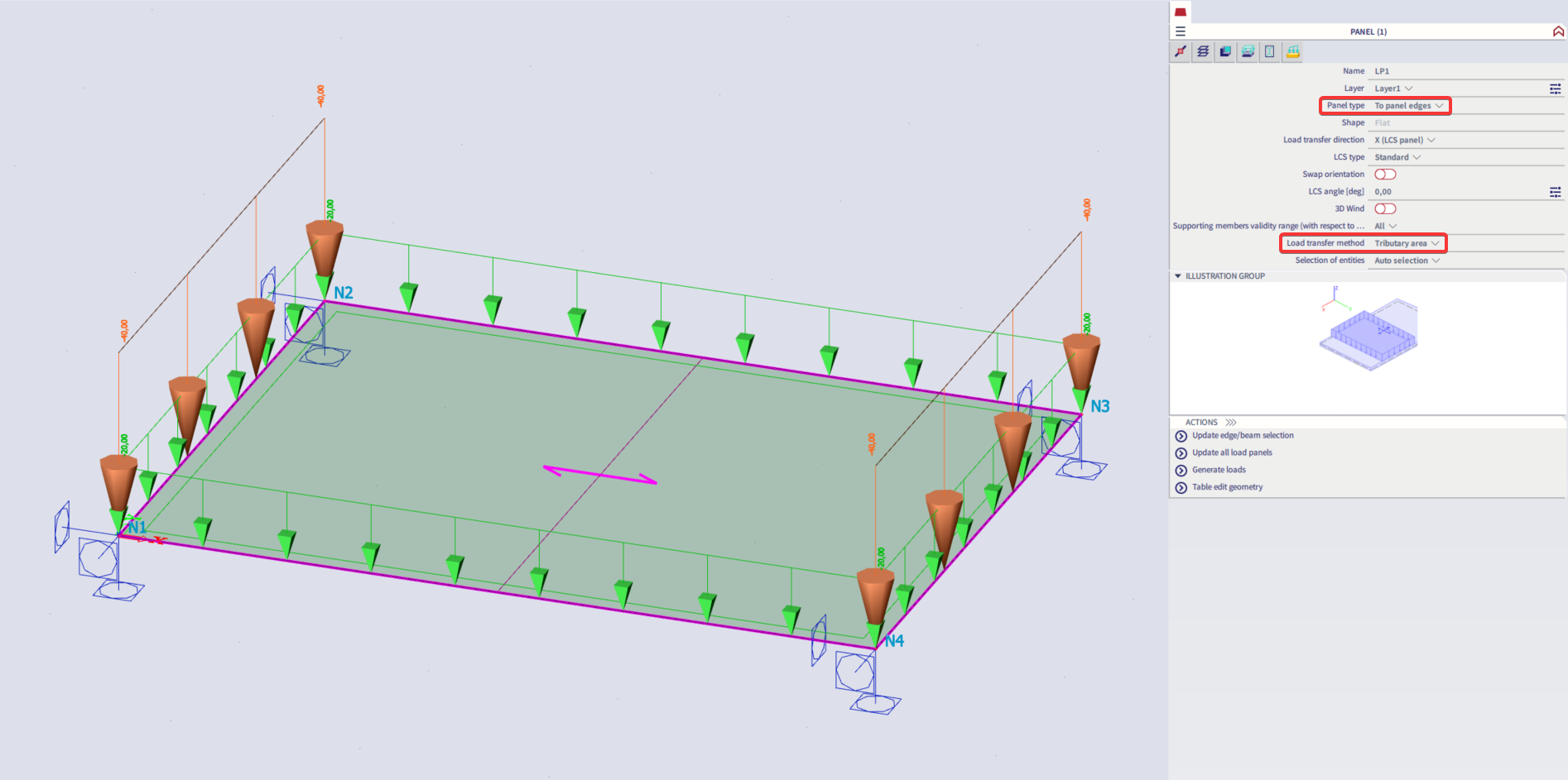
A panel of this type transfers the applied load to all or selected edges of the panel. The load is generated only along supported edges.
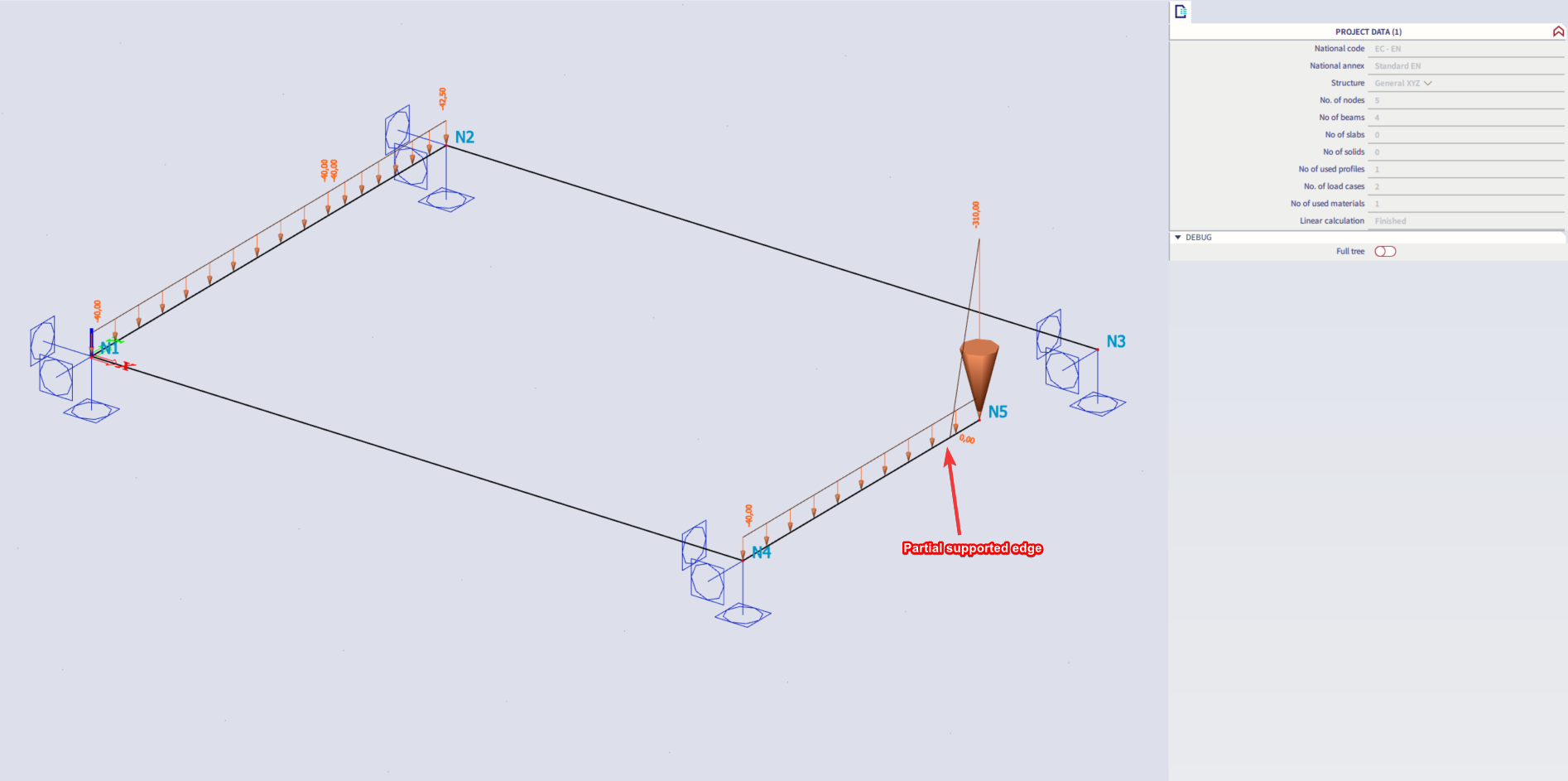
Supports can be formed by beams or edges of 2D members. It is not possible to define a direct support on the load panel. If an edge is only partly supported, then a point load is generated at the end of the support.
The panel supports can be displayed. All load types can be used on the panel. The panel is available in all project types: 'Frame', 'Grid', 'General'...
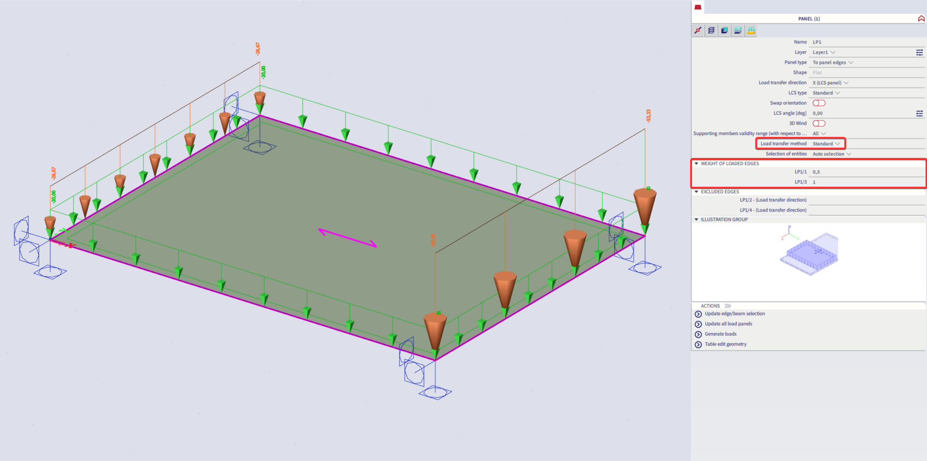
You can choose two methods for transferring the load to the edges (for more information see following FAQ: Load transfer method on load panel):
- Standard
The total load is distributed to edges proportionally to the length of the edges. The user can adjust the weight for individual edges or exclude some of them (by inputting 0).
- Tributary area
The edges are loaded based on the tributary area of the particular edge.
Load to opening edges
This type is analogous to the previous one. The difference is that for this type an opening is defined where the load is transferred to the edges of the opening. The properties of such load panel are limited.
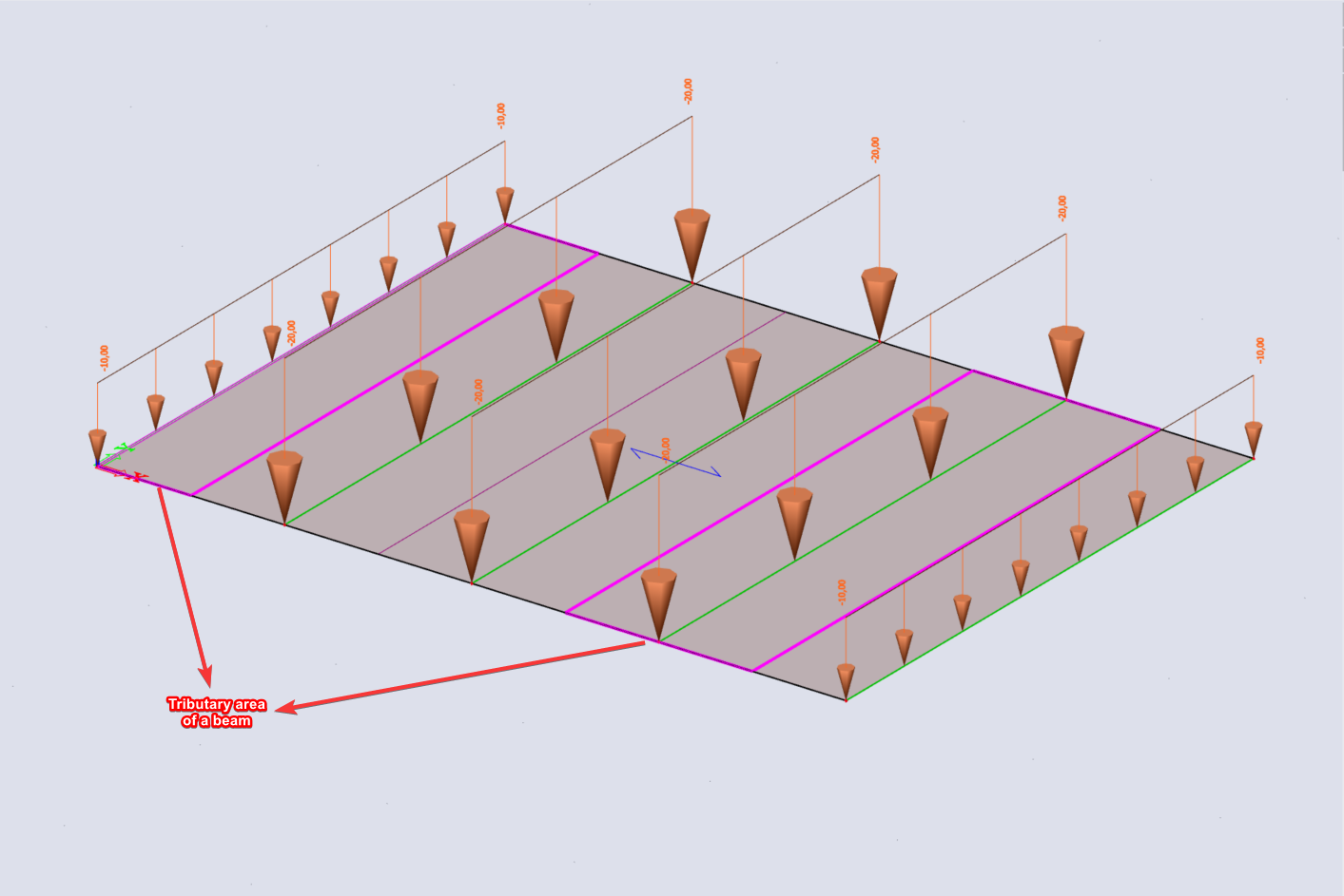
Load to panel edges and beams
A panel of this type transfers the applied load to all or selected beams that are located (with a defined tolerance) in the plane of the panel. If the panel has some edges supported, these supported edges are treated like beams, i.e. the load is transferred to them as well. It is not possible to define a direct support on the load panel. All load types can be used on the panel, only when using a free load on the panel you should use the transfer method 'Accurate (FEM)' since this type of load is not compatible with the other load transfer methods. The panel is available in all project types: 'Frame', 'Grid', 'General'...
The option 'Max. angle for transfer [deg]' is available for this panel type. When the beams are not perpendicular to the panel direction and the angle is higher than the Max. angle for transfer, then the load is not generated on those elements. The user has to adapt the parameter to deal with this situation. The default for this value is 5 degrees.
You can choose a method that transfers the load to the beams (for more information see following FAQ: Load transfer method on load panel). There are the following methods available:
- Standard
The total load is distributed to beams proportionally to the length of individual beams and supported edges. The user can set the weight factor for individual beams or exclude some of them (by inputting 0). - Accurate (FEM)
The finite element method is used to recalculate the applied load to individual beams. This method should be used when applying free loads on the load panel. - Tributary area
The beams are loaded based on the tributary area of the particular beam. The tributary area is defined based on the geometry of the load panel.
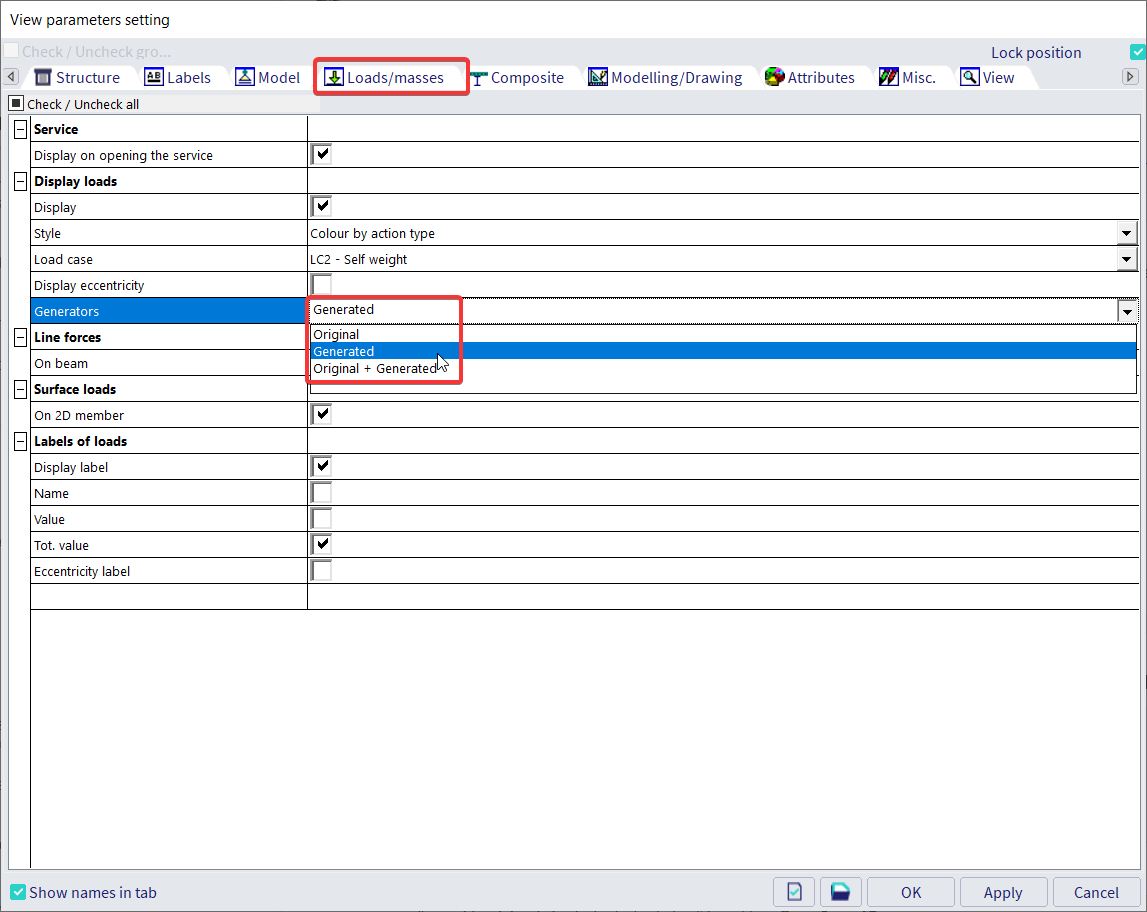
You can display original load, generated load or original + generated load via View parameters setting.