Application of the design code for steel fibre reinforced concrete into finite element software
L Dlouhý, SCIA CZ, Slavíčkova 1A, Brno. Czech Republic
S Pouillon, N.V. Bekaert S.A., Bekaertstraat, B-8550 Zwevegem, Belgium
FIBRE CONCRETE 2019
IOP Conf. Series: Materials Science and Engineering 596 (2019) 012009 doi:10.1088/1757-899X/596/1/012009

Abstract.
Steel fibre reinforced concrete (SFRC) is more and more used as construction material. Well-known are applications for industrial floors. Nevertheless, this material is also widely used in structural concrete elements where it is especially effective to cover crack widths in combination with standard conventional reinforcement. Currently there is no general part in Eurocode 2 [1] for buildings regarding steel fibre concrete. There are various standards and recommendations for the calculation of the steel fibre contribution. One of the most applied publications is the German guideline DAfStb [2] which was used as a basis for the numerical analysis outlined in this paper. Thus, company SCIA N.V. together with Bekaert N.V. as producer of DRAMIX® fibres developed a special tool for designing and checking SFRC structures. This tool was built in into finite element software SCIA Engineer and based on the German guideline. To gain a fundamental understanding of the structural behaviour, we have also developed non-linear FEM models, which contain a built-in module for SFRC structures. Numerical simulation results are compared to experimental performance of SFRC slab on piles of the Nanhui project in Shanghai in terms of ultimate load and crack pattern.
1 Introduction
An expansion of new materials brings together with it higher demands on their design. This is valid also in case of concrete structures with steel fibers. When steel fibers are added to concrete matrices this leads to significant tension stiffening and higher toughness of the resulting material. The main question remains how to effectively verify such kind of structures. There is no general part in Eurocode 2 [1] for buildings regarding steel fibre concrete. There exist only recommendations like RILEM [3], Model code 2010 [4] from 2014 and mainly the German guideline DAfStb [2] which was used as a basis for the numerical analysis outlined in this paper. This guideline also extends the German national annex DIN EN 1992-1-1/NA. Currently preparation is already ongoing of the new draft of Eurocode where a special chapter about steel fibre reinforced concrete is presented in part L of this code.
The first complex solution on the market is resulting from the cooperation of the top worldwide producer of steel fibers DRAMIX®, Bekaert N.V. and SCIA N.V., a developer of software SCIA Engineer for finite element analysis of structures. The proposed solution is integrated into the program combining (i) a material library for a selection of predefined DRAMIX® steel fibres and (ii) a calculation tool providing design and check features of steel fibre concrete structures based on the German guideline DAfStb [2]. The design approach implemented in SCIA Engineer in relation to the DAfStb from 2012 is described in this paper.
2 Structural steel fibre concrete structures in SCIA Engineer
SCIA N.V. together with Bekaert N.V. developed a unique solution for designing and checking of steel fibre reinforced concrete slabs. This is a one of the first known implementation of such a feature into finite element software (in this case SCIA Engineer). Bekaert N.V. provided their long-term knowledge in development and production of DRAMIX® steel fibres. A special library for steel fibre reinforced concrete is built-in for different concrete classes and dosages based on the selected DRAMIX fibre type. There are 3 basic types of DRAMIX® steel fibres included: 5D65/60BG; 5D65/60GG and 4D65/60BG [5].
The verification of the structure is performed based on ultimate limit state (ULS) checks:
- check capacity (normal forces + bending moment),
- shear check,
and serviceability limit state (SLS) checks:
- crack width check,
- stress limitation.
Moreover, it is possible to verify local effects of column-punching on the slab. All the checks can be run on a fixed dosage or an optimized dosage based on the ultimate limit state. An equilibrium system for this state can be achieved if at least one of the following conditions are met (i) analysis with redistribution of moments within statically indeterminate systems, (ii) combination with reinforcement or (iii) normal compression due to external actions.
2.1 Material characteristics
2.1.1 Characteristic tensile strength on material level.
The calculation of material characteristics is dependent on the fibre type and dosage and based on DAfStb. The mean residual strength values fR1,m and fR4,m are the basis for the calculation of the material behaviour (σ - ε). They are determined by means of beam tests and are mainly influenced by fibre type, dosage and concrete performance. The characteristic residual flexural strength values (ffcflk,L1; ffcflk,L2) are derived from the mean values. As these mean values are based on a high number of tests, it can be assumed that the threshold (0.51 fR) is reached in all cases – see formula O.3 from the DAfStb Guideline [2]. The calculation of the characteristic residual tensile strength values (ffct0,L1; ffct0,L2; ffct0,u; ffct0,s) is the next step of the process. In principle, the characteristic residual flexural strength values are multiplied with a beta factor. Determination of beta factors (βL1 and βL2) is done based on figures P.1 and P.2 from DAfStb [2].

In SCIA Engineer, these characteristic residual tensile strength values are listed in the material library in function of the fibre type, dosage and concrete class.
2.1.2. Characteristic tensile strength on structural element level.
The second step in the calculation of the material characteristics is the calculation of residual values from characteristic ones by considering the member size and the fibre orientation effect in the calculation. By default, considering a large, horizontally casted slab, following values are taken into account:
kfc =1,7; member size effect; with one factor per material and per slab
kfc fibre orientation effect (1,0 for bending and tensile loads; 0,5 for shear)

2.1.3. Design values
The last step in the calculation of material characteristic concerns the calculation of design values from characteristic ones by applying the reduction factor (αfc =0,85) for long-term effects and the partial safety factor (γfct =1,25) according to Table R.1 from [2] on the residual tensile strength of the steel fibre reinforced concrete.

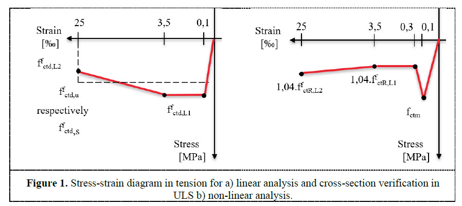
2.1.4. Material diagrams.
The material diagrams are different than those of standard concrete material. The effect of fibres is considered by the tensile branch. Here only the behaviour in tension is described. There are two types of material diagrams used in the analysis, dependent on the analysis type, see Figure 1.
2.1 Dosage design and check capacity in ultimate limit state (ULS)
The determination of the optimal dosage design is based on an iterative calculation of the ULS capacity loaded by a combination of normal forces and bending moment. The procedure searches the optimal fibre dosage in each finite element of the structure to reach maximal exploitation 100% and obtain equilibrium. The effect of conventional reinforcement is also included in the calculation in case this reinforcement is defined. The equilibrium of the cross-section is demonstrated on Figure 2. This figure clearly indicates the main advantage in the usage of steel fibre concrete in tension due to the existence of the steel fibres. The basic assumptions are also valid for steel fibre analysis:
- Steel fibre reinforced concrete is active in compression and in tension
- Plain section remains plain after load application
- Bending moment and normal force equilibrium on cross-section
- Parabolic rectangular stress-strain diagram in compression is used, maximal strain in compression is dependent on concrete class
- Stress-strain diagram in tension is visible from figure and maximal strain in tension is 25‰
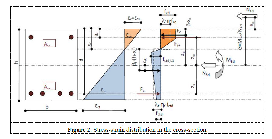
The equations for static equilibrium of normal forces and bending moments are indicated in the following formulas.

2.3 Shear capacity and punching
The effect of steel fibres (νRd,cf) is considered in the calculation of the total shear resistance (νfRd,c) in addition to the regular shear capacity of concrete (νRd,c). The steel fibres behave as spread reinforcement and participate on the transfer of the shear loading. This can lead to significant savings on the traditional shear reinforcement, or even neglect it completely.

The shear concrete capacity νRd,c is calculated based on chapter 6.2 from the code [1]. The incrementation of the capacity caused by the steel fibres is expressed according to 6.2.2 [2] and it is dependent on the material characteristic of steel fibre concrete as follows.

Where ffct,R,u– characteristic residual concrete strength in ULS [MPa].
Additionally, the final value of the shear capacity of steel fibre concrete is limited by 140% of the shear capacity of traditional concrete.

The steel fibre contribution is considered in the same way in case of a punching verification. Nevertheless, when the required area of conventional reinforcement for punching is designed then based on Re 6.4.5 [2] the effect of fibres cannot be taken not account and only concrete without fibers is analyzed.
2.4 Crack width and stress limitation
The calculation of crack width corresponds to basic assumptions of the Eurocode standard for traditional concrete [1]. The effect of fibres is considered by an additional factor αf, which is the ratio of the characteristic residual strength in SLS (ffctR,s) and the mean tensile strength of concrete (fctm).
![]()
Where maximal crack spacing (sr,max) is calculated as

And the difference of mean strain value of concrete and reinforcement (εfsm - εcm)

where:
- εfsm – mean strain in reinforcement
- εcm – mean strain in concrete between cracks
- αf – the ratio of characteristic residual strength in SLS (ffctR,s) and mean tensile strength of
- concrete (fctm).
- Φs – diameter of reinforcement
- ρp,eff – effective ratio of reinforcement
- fct,eff – effective tensile concrete strength
- Es – modulus of elasticity of reinforcement
- σs - stress in the reinforcement
In case of steel fibre concrete without conventional reinforcement it is necessary to apply a different approach where the crack width is calculated based on the following formula according to [2].

where:
- sfw– 140 mm
- εfct– strain in steel fibre concrete
When the crack width is presented in the cross-section then the check of stress limitation usually doesn’t satisfy. The basic assumptions are the same as for the crack width calculation. The following list of stresses in particular components are checked in this verification:
- Stress in concrete from characteristic combination based on 7.2 [1]
- Stress in concrete from quasi-permanent combination based on 7.2.(3) [1]
- Stress in conventional reinforcement from characteristic combination based on 7.2.(5) [1]
The stress in conventional reinforcement is calculated without fibres being present which leads to fictitious values. As such this value can be higher than the yield strength. The effective steel stress, taking into account the presence of the steel fibres, should be calculated and compared to the reinforcement strength limit. The effective steel strength is calculated as follows:
![]()
3 Physical non-linear analysis
As steel reinforced fibre concrete is being used more often, the real behaviour and investigation of the structure is essential. Especially for steel fibre reinforced concrete this non-linear analysis can provide the real behaviour of the structure with different results compared to the linear analysis. This behaviour is heavily influenced by the crack formation which is typical for fibre concrete. The toughness of fibre concrete is significantly increased by the existence of steel fibres up to values very close to standard reinforcement.
Physical non-linear analysis represents a very powerful tool for analysing any kind of structure in civil engineering created not only from steel fibre reinforced concrete but also from other materials. Generally, there could be significant differences of results compared to a linear analysis, especially in case of hyper-static structures. In case of linear analysis, only the E-modulus of the material is considered for the preparation of the stiffness matrix. There is no stress distribution based on increasing the strain in the component. On the other side the non-linear analysis provides a stress distribution and increase of the bearing capacity after reaching the ultimate strain until the collapse mechanism. This mechanism is based on different values of stress and strain, dependent on a predefined non-linear stress- strain relationship in the material diagram as defined on Figure 1.
The damage Mazarz material model is used for the non-linear calculation. This model efficiently enables the considered stress-strain diagrams with descending branches which is typical for steel fibre concrete in tension. The practical application of the non-linear analysis is demonstrated on a real test project of a foundation slab on piles in Shanghai [6].
3.1 Foundation slab on piles (Nanhui project in Shanghai)
In order to investigate the real behaviour of SFRC slabs on piles, a campaign of tests has been conducted at the Tongji University of Shanghai, China. The load test was performed on SFRC slabs from C40/50 and dimensions 4,3m x 4,3m with thickness 187,5mm supported by rectangular supports representing the piles, see Figure 3. There were used slabs with DRAMIX 5D fibres with 30kg/m3 and 35kg/m3. The load was imposed gradually by a hydraulic jack from the bottom to the top. At first the material characteristics were established by laboratory tests on 6 specimens based on EN14651 where especially their residual strength L1 and L2 were determined.
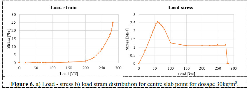
The presented non-linear model provides a good match with the experimental test. The comparison of the results with the load-displacement diagram coming from the test is visible on Figure 4 for Dramix fibres 5D65/60BG with dosage 30kg/m3 and 35kg/m3. This capacity is at the load level 283,9kN (299,0kN for 35kg/m3 respectively) where the ultimate tensile strain in steel fibre reinforced concrete (25‰) is reached.
The tight peak in the tension part of the diagram works as a “crack localizator”. This is perfectly visible in Figure 5 where the load is continuously increased. The red colour represents the stress close to the tensile strength and continuous cracking of the slab from the centre of the slab to the edges. The extending middle part to the edges uses just the residual tensile strength of the steel fibre reinforced concrete after cracking. Additionally, these stresses show the places with crack formation in the middle of the slab and their spreading of cracks during the increasing of the load.
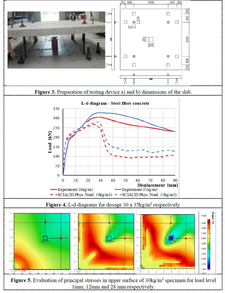
Figure 6 represents a graph of the dependency between the load level and the stress-strain for the most critical point in the middle of the slab and upper fibres. When looking at the Load-Stress distribution, it can be deducted that the behaviour of the structure is linear till load level 55kN. The structure is approaching the top of the stress strain diagram peak. A strain very close to 0.1‰ is reached. After that there is a phase of crack formation and the stress is coming down significantly based on the stress-strain diagram. The residual strength in tension (1,09MPa) is reached nearly at load level 100kN corresponding to a strain of 0,3‰. A load higher than 100kN means the spreading of the cracks with smooth hardening of the material done by the increasing branch of the stress-strain diagram in tension till maximal value of 1,13MPa and the plastic load is reached by the load of 283,9kN where the strain reaches the limit of 25‰.

4 Conclusions
SCIA N.V. together with Bekaert N.V. developed a unique solution for designing and checking of steel fibre reinforced concrete slabs based on the latest standard DAfStb [2]. This tool brings new possibilities for a very fast and easy design and check of steel fibre reinforced concrete.
In addition, a non-linear analysis method has been developed for simulating the real behaviour of the structure based on the non-linear stress-strain diagram with respect to cracks. This analysis method was proven to provide a very good comparison with real-life test results. A comparison was done for the deflection of two slabs made from C40/50 with fibres DRAMIX 5D 65/60BG and dosage 30kg/m3 and 35kg/m3 respectively. The comparison of the maximal loading capacity mentioned in Table 1. clearly indicates the higher maximal load is achieved by the test. This indicates the non-linear FE calculation provided in SCIA Engineer is on the safe side.
References
[1] EN1992-1-1, Eurocode 2: Design of concrete structures - Part 1-1: General rules and rules for buildings
[2] DAfStb-Richtlinie, Stahlfaserbeton, Ausgabe November 2012
[3] RILEM TC 162 TDF, Design of Steel fibre reinforced concrete – Method, recommendations, Material and Structures, March 2001
[4] ModelCode2010, The fib Model Code for Concrete Structures 2010
[5] https://www.bekaert.com/en/product-catalog/construction/dramix/all-round-concrete-reinforcement-solution
[6] Dlouhý L and Roland R 2018 Proc. Fibre Reinforced Concrete: from Design to Structural Applications Joint ACI-fib-RILEM International Workshop (Desenzeano de Garda Italy) p 74

Want to try SCIA ENGINEER yourself?
Explore how our software and services can help you optimise your work and boost your productivity. Try it for yourself with a free 30-day software trial.
Download a free 30-days full trial