Licence improvements
SCIA Engineer version 24 brings improvements for more effective use of licences in larger organisations.
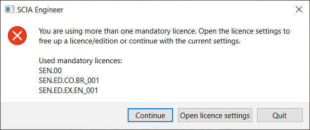
Warning for multiple licences use
When using more than one mandatory licence or ‘edition’, the user is warned upon startup. The user can choose to continue with the offered selection, or to change the selection of modules directly in the licence settings.
If more than one mandatory licence is selected, this information is also displayed in the licence settings dialog.
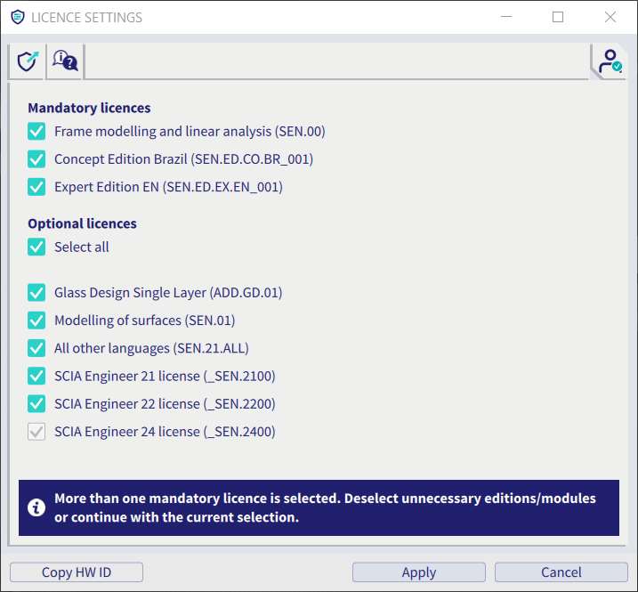
While it is possible to use complementary editions to cover all functionalities used in a project, it is often not needed to use more than one licence at a time. Informing the user that more than one licence is used will help use the licences more efficiently and free up unnecessary licences for colleagues.
Link to web help
As can also be seen in the previous picture, the toolbar in the dialog contains a new button that directly opens the help page for licence settings. Here the user can find any information they might need.
UI improvements
SCIA Engineer version 24 brings some improvements to components and tools in the graphical user interface.
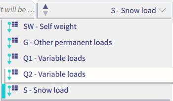
Description of load cases
The master entity selector (load case, modification group, mass group and construction stage selector) in the status bar has been enlarged to show also the description of the active entity. This allows the user to easily identify the active entity.
Repositioning and switching the process toolbars
The process toolbar can now be dragged to a new position more easily thanks to a new drag handle and dragging area. As a result, when you are making a selection box close to the toolbar, you will no longer accidentally move the toolbar. The ‘switch toolbar’ icons for process toolbar and view bar have been updated as well.

Properties panel default setting
The default setting for the properties panel is now on ‘advanced’. This means that all properties can be found at first glance.
Template configurations
SCIA Engineer version 24 brings 4 template configurations to boost your confidence and productivity.
The new user interface introduced in version 21 is fully customizable. And our example templates can make it even easier for you to find a configuration that fits your needs.
There are four templates available, tailored to specific a specific workflow:
- Transition from the old UI
- Concrete
- Steel
- Scaffolding
For more information read a dedicated fact sheet...
Analysis
New Solver manager
With SCIA Engineer version 24 the data handling system between the preprocessor and the finite element solver parts of the software has been totally re-implemented. As a result, users can take full advantage from of the power of modern multicores processors via parallel computation.
Design situations for which the computational time was a pain point in the past (nonlinear and stability analyses whit many combinations) are now drastically improved. With SCIA Engineer 24, nonlinear and stability combinations run in parallel, with each core of the PC working on a different combination at the same time.
The more cores are on the PC processor, the faster the computation of the whole project is.
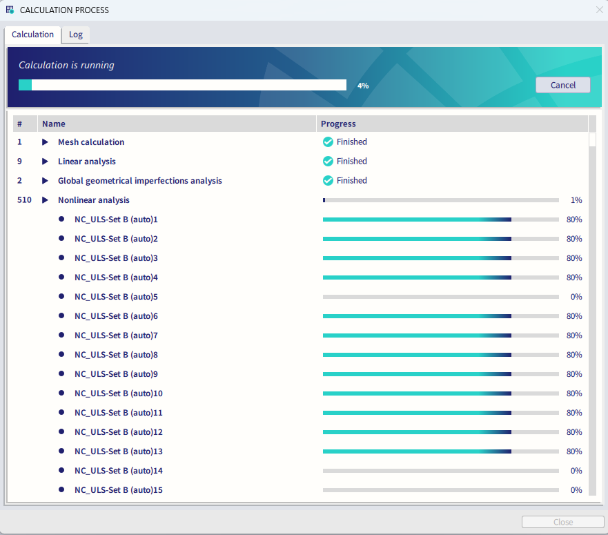
Figure: The new calculation process window shows the progress of the parallel computation
Moreover, the advances brought by the new Solver Manager are not limited to performance but the whole behaviour of the solver experience has been improved:
- It is now possible to stop the whole running analysis at once, just with a click.
- The end-of-analysis warnings and error messages have been reviewed and give now a clearer overview of the calculation process and results.
- The singularity window, which previously was systematically and automatically shown at the end of failed analysis is now opened on users’ demand.
New Construction Stages
A brand-new Construction Stages functionality has been implemented in SCIA Engineer 24.
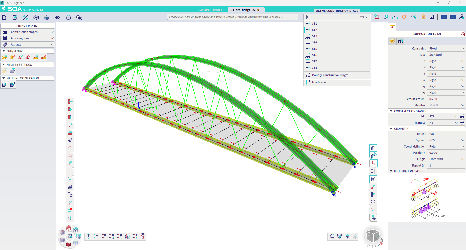
Figure: The addition/removal of items over stages has been largely extended with respect to the previous solution
The new solution allows the following model modifications over stages:
- addition/removal of 1D members, 2D members and pre/post tensioned tendons,
- addition/removal of all types of hinges,
- addition/removal of all types of supports,
- modification of material stiffness (Young modulus),
- computation of staged cross-sections with no limits in stages and possibility to add, remove and re-add parts of the cross-sections.
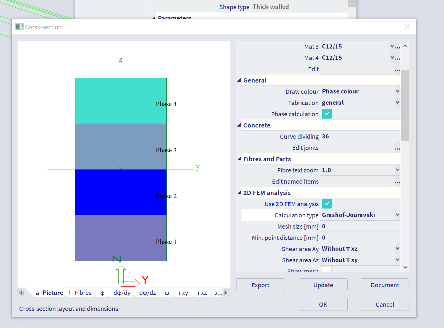
Figure: Phased cross-sections can have an unlimited number of phases, and these can be added, removed and re-added.
Global imperfections visualization
As from version 24, the deformation produced by the application of a global imperfection can be visualized. Global imperfections can be defined, computed and visualized before being applied to the nonlinear analysis. Consequently, this added transparency enables the user to check the initial deformed shape beforehand and then confidently run the (often time-consuming) nonlinear analysis.
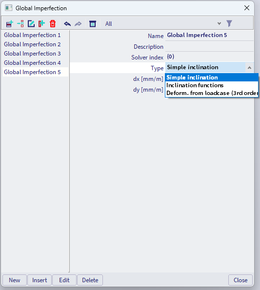
Figure: One or several global imperfections can be defined in the project
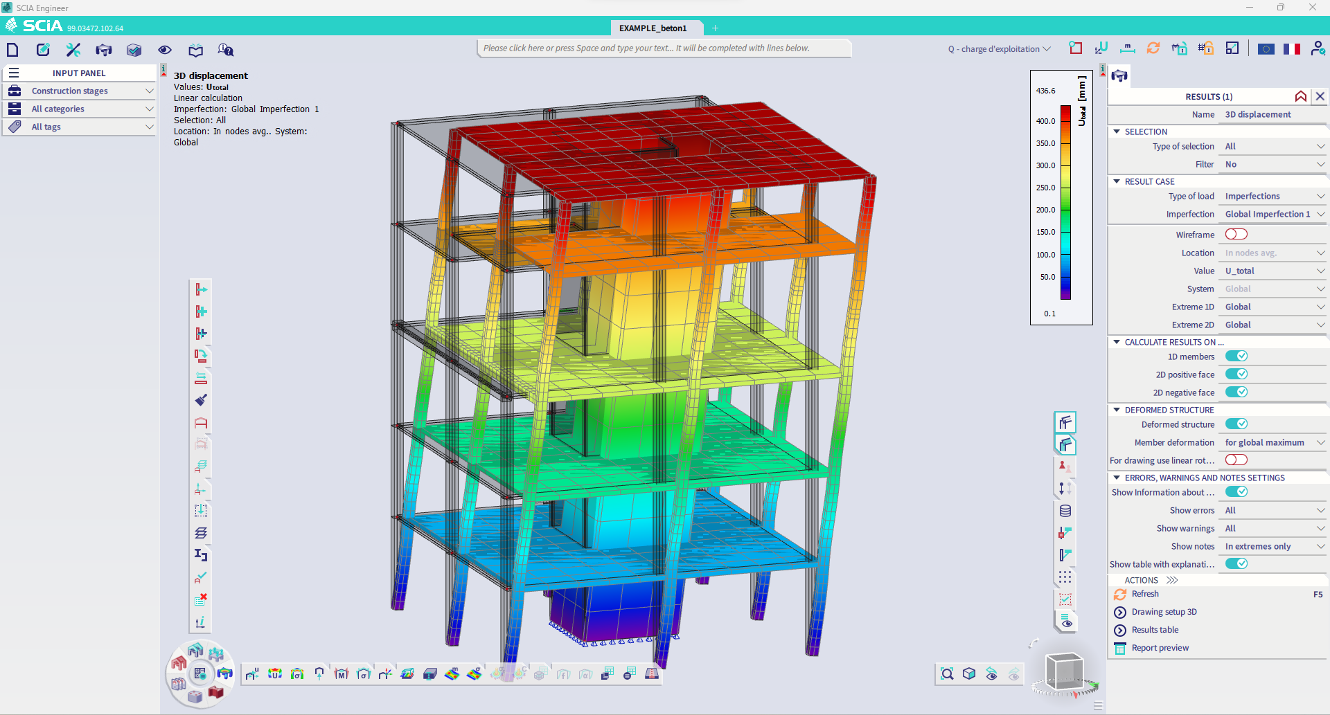
Figure: Global imperfection can be visualized and checked
New Nonlinear stability analysis settings
The settings for a nonlinear stability analysis have been reviewed to provide more control over individual steps in this complex calculation. The new control setup helps the user to reach the analysis’s convergence in an easier and quicker way
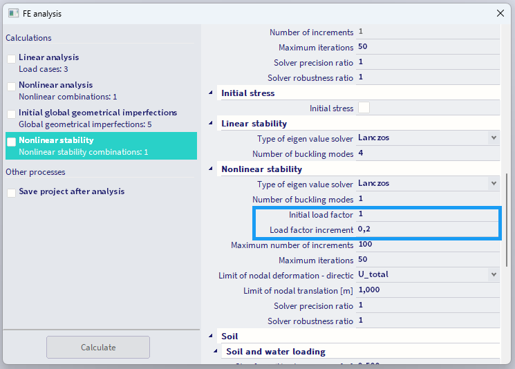
Figure: New parameters (initial load factor and load factor increment) help the user in reaching the analysis convergence in an easier and quicker way.
The nonlinear stability analysis applies the load incrementally until the structure collapses. If the augmentation of the load is too slow, reaching of the collapse can take very long; if the augmentation of the load is too rapid, the convergence is quickly lost.
Therefore, with a constant load increment over all the calculation step, the analysis would be either too long or too difficult to converge. Version 24 splits the control of the load increment into two different parameters. Parameter “initial load factor” allows to set up the amplitude of the first load increment, which aims at getting close to the collapse but not reaching it. Parameter “load factor increment” aims at fine tuning of the load increments after the first load increment has been computed, in order to precisely get the collapse point.
Automatic assignment of the sign of results for seismic response spectrum analysis
The assignment of the correct sign (+/-) to the results of the seismic response spectrum analysis is now fully automatic: the user does not need any more to manually look for and select predominant modes. The software automatically identifies and assigns the predominant mode shapes to the respective seismic load cases and then assigns the sign to the results accordingly. The benefit for the user is the certainty of most accurate results when seismic response spectrum analysis is performed.
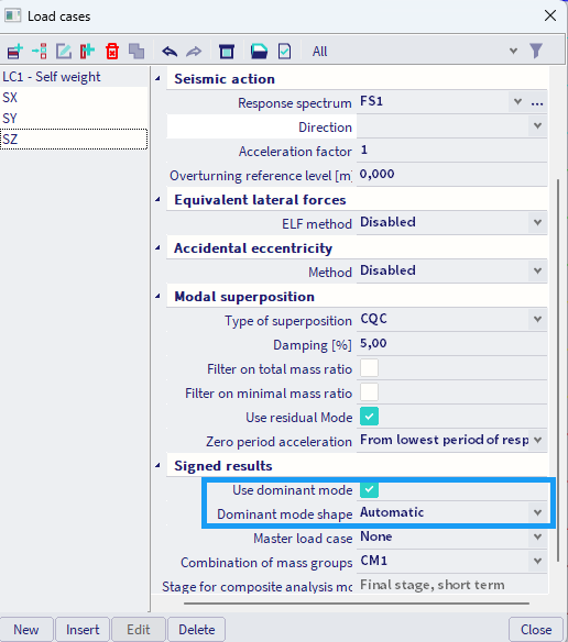
Figure: The user only needs to enable the use of the dominant mode and then select the automatic determination of the dominant mode shape
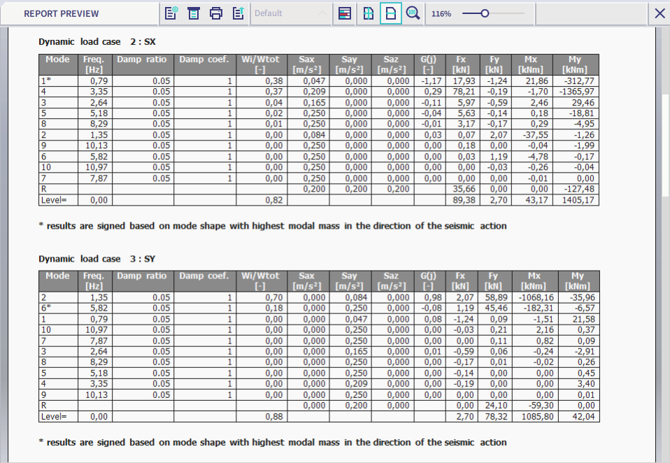
Figure: The sign of seismic results is determined based on the dominant mode shapes, the dominant mode shapes are highlighted in the calculation report (in this example mode n°1 for direction X and mode n°6 for direction Y)
Nonlinear material behaviour analysis for RC structures
Starting with version 24, there is a possibility to perform an analysis of reinforced concrete structures (for both 1D & 2D members) accounting for the nonlinear material behaviour of both concrete and reinforcement steel. The users can utilize the Mazars’ damage law for the concrete and an elastoplastic law for the reinforcement steel. In addition, they can define themselves the material behaviour laws to be used in the analysis. This new feature allows the users to accurately simulate the fragile behaviour of concrete and the plastic behaviour of the reinforcement steel, thus enabling a precise and realistic estimation of the structural deformation and stress distribution.
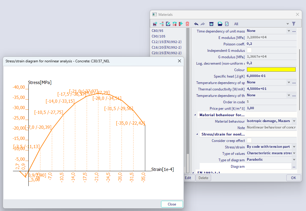
Figure: Mazars’ damage law for nonlinear analysis of concrete
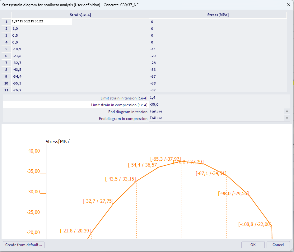
Figure: Possibility to input a user-defined stress/strain diagram for a nonlinear calculation.
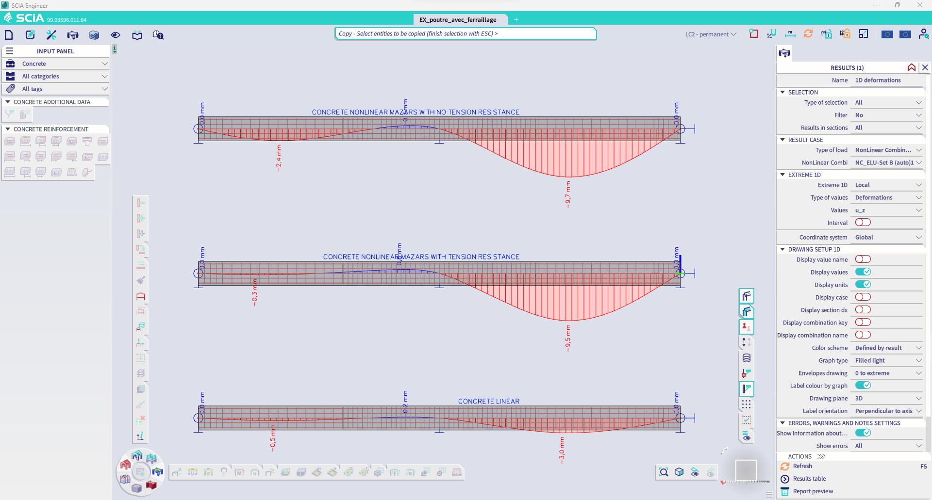
Figure: Example deformation of a RC beam computed linearly and nonlinearly with Mazars’ law
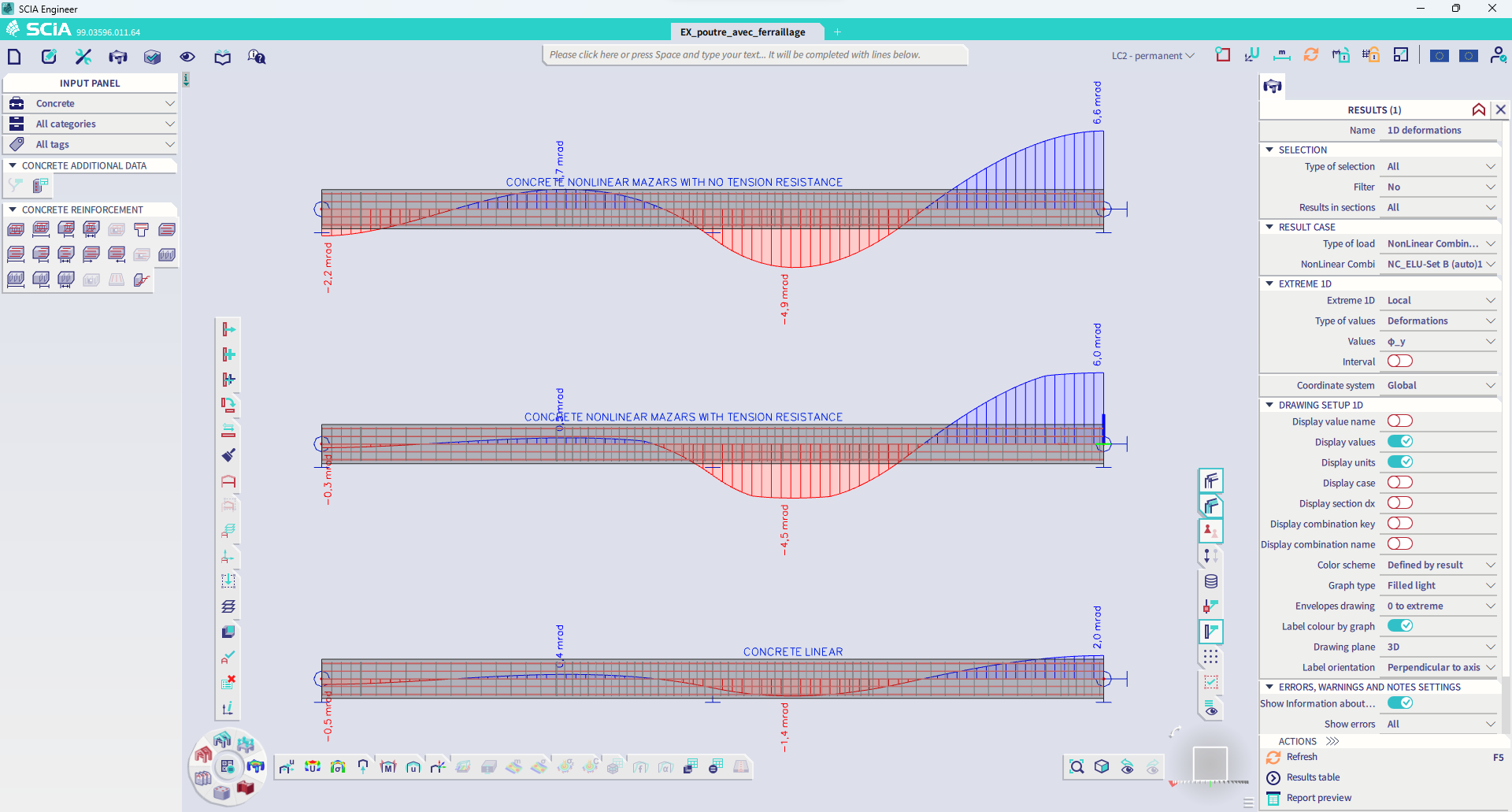
Figure: Example deformation of a RC beam computed linearly and nonlinearly with Mazars’ law
New Code Dependent Deflection (CDD) calculation
The calculation of the code-dependent deflection can now take into account local nonlinearities, eccentricities, orthotropy and stiffness modifications. Moreover, it is also possible to obtain results in both global and local reference systems and the calculation is accelerated by the parallel computing enabled by the new Solver Manager. The benefit for the user is the possibility to correctly and accurately model and analyse most of scenarios that can be encountered in engineering practice.
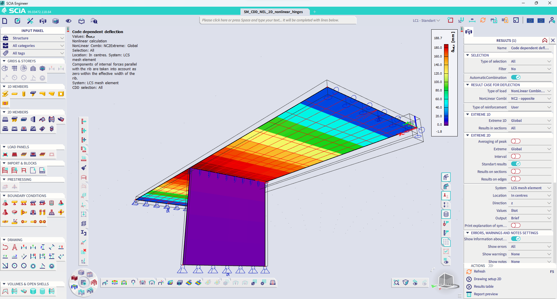
Figure: Example, code-dependent deflection with nonlinear hinges at midspan (pressure only)
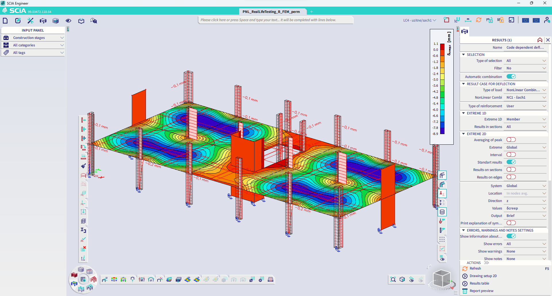
Figure: Example, code-dependent deflection; creep deflection with respect to global coordinates system.
New Automatic Mesh Refinement
SCIA Engineer 24 introduces a new algorithm for an automatic refinement of the finite element mesh on 2D members. The new solution is fully automated: when starting the analysis, the user only needs to choose the target mesh error. Then the mesh is automatically optimised, and the analyses is performed. The benefit for the user is the certainty that the used mesh is sufficiently fine to obtain results of the required accuracy.
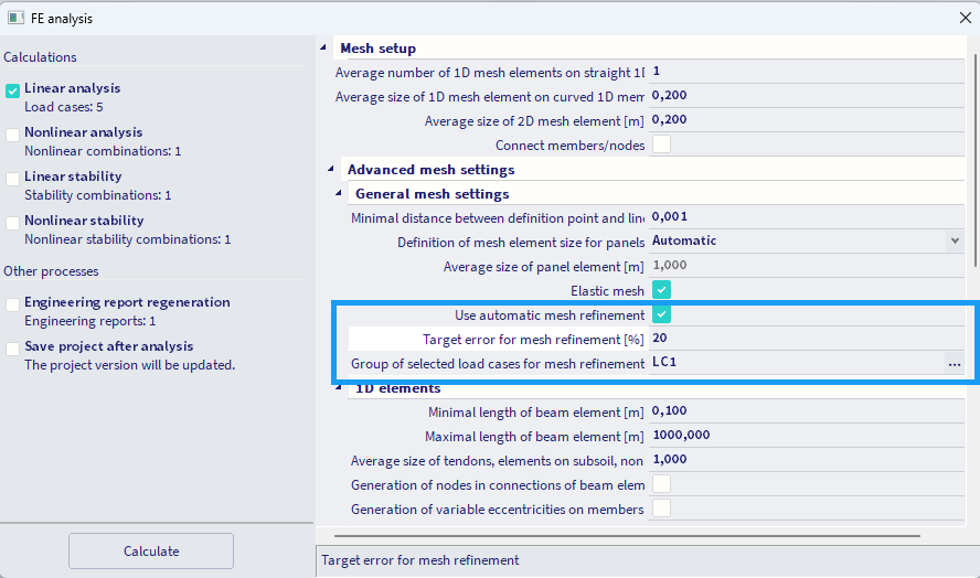
Figure: The user only needs to select the target mesh error, then the mesh is automatically optimized and applied to the whole calculation
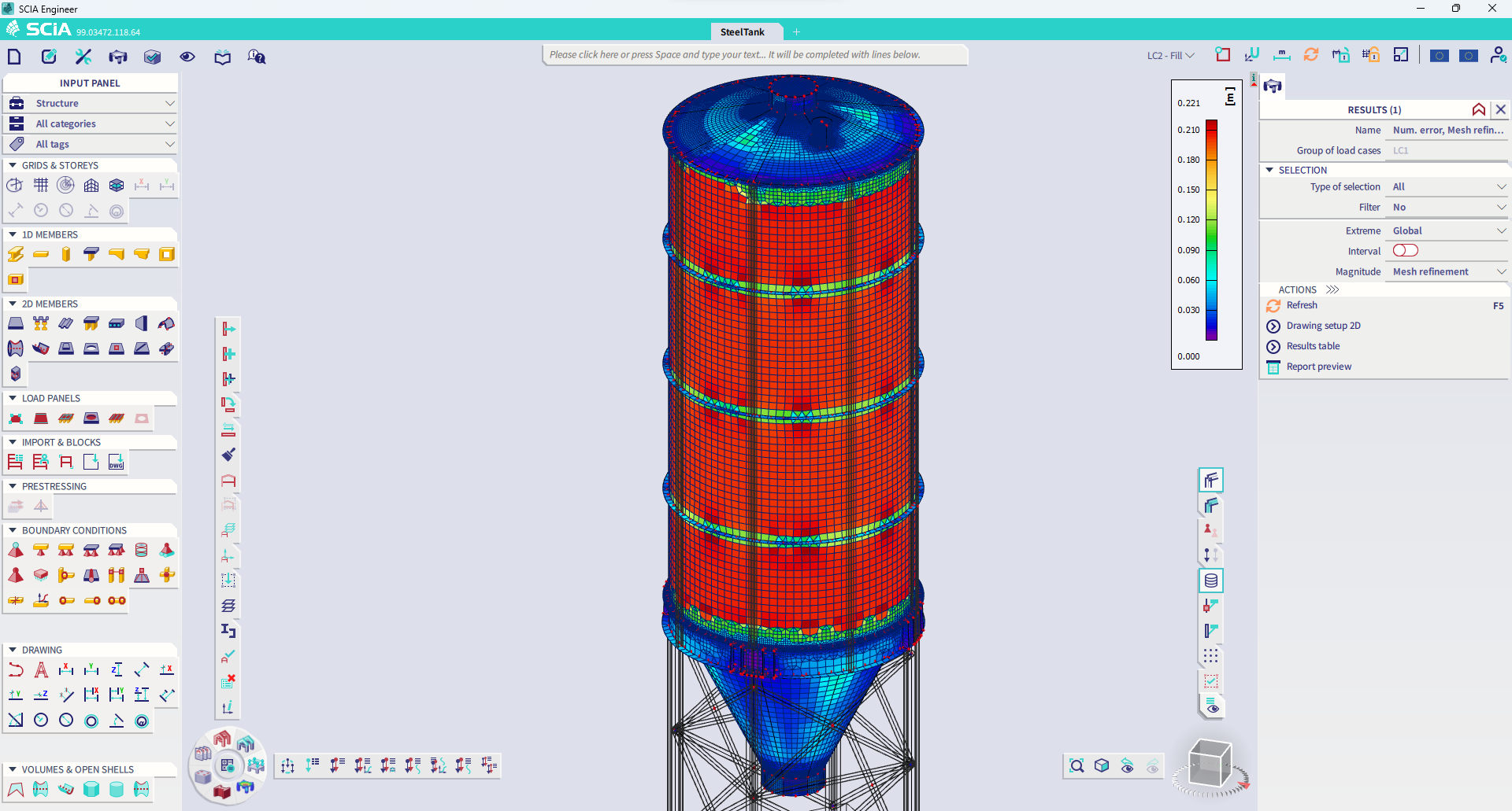
Figure: Example automatic mesh refinement on a steel silo
Material design
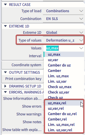
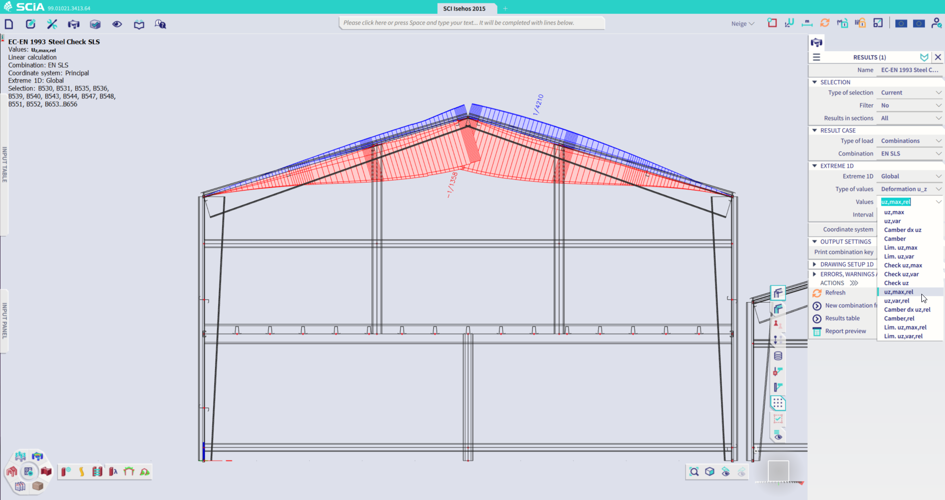
Relative unit for SLS design
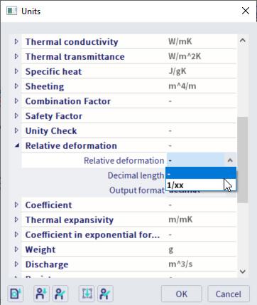
Voted as the top item in the customer poll, it is now possible to display the relative deflections calculated in the SLS check as a relative (L/xxx) value. The new format is available for the results shown on screen as well as results in the result tables.
For now, the new option is available for steel and aluminium SLS design. After changing the ‘type of values’ to ‘deformation uy/uz’ in the SLS check menu, it can be found under ‘values’, where all the options with ‘rel’ added to their name will show the results in relative units instead of length units. In the unit settings, it is possible to adapt the relative unit to a decimal, adapt the decimal length and the output format.
Concrete design template as list of diameters/spacings
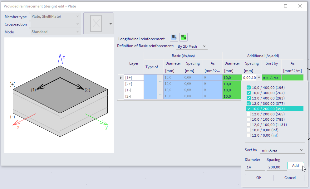
This improvement is also one of the features selected by our users in the regular yearly poll. In previous versions, the design template for the provided 2D reinforcement allowed to define either a list of spacings for a fixed diameter or a list of diameters for a fixed spacing. This has now been extended to accommodate lists of diameter-spacing pairs.
The user is now able to add spacings and diameter options to the list, and then select which combinations of those diameters and spacings should be used for the design.
Restrained by sheeting: Enforce a local axis check
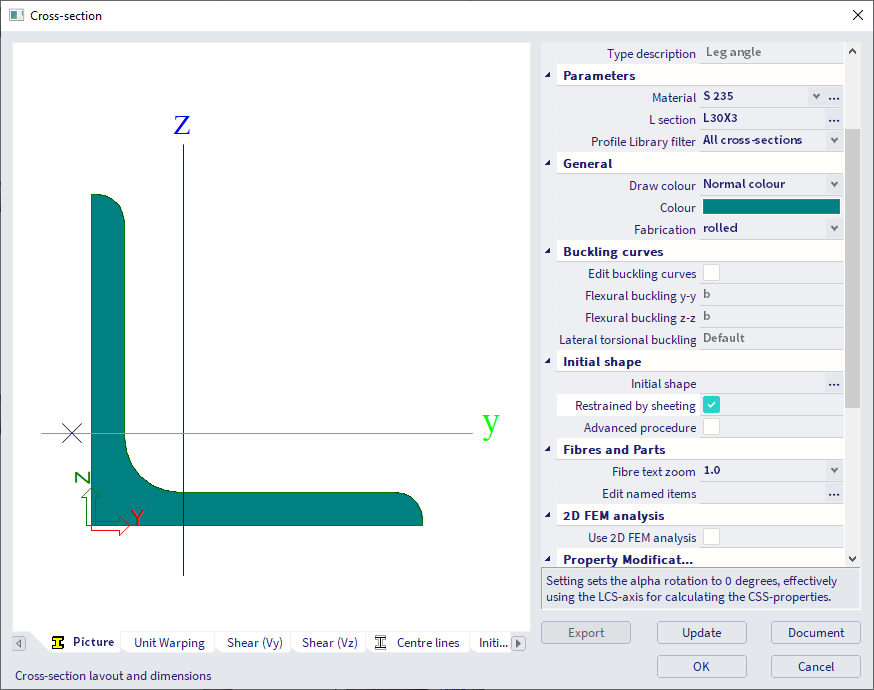
For all sections with an initial shape, both steel and aluminium, that are asymmetrical - or in other words, where the principal and local axis are not aligned - a new option is available: “Restrained by sheeting”.
When this option is activated, the software neglects the fact that the principal axes are rotated with respect to the local axes and performs all checks for this cross-section according to its local axes. In the check, a warning is printed to inform the user about the altered behaviour. This option is needed for sections that can move only according to local axes, for example because they are connected to a floor or sheeting.
Scaffolding updates and improvements
The following 3 improvements have been implemented for scaffolding:
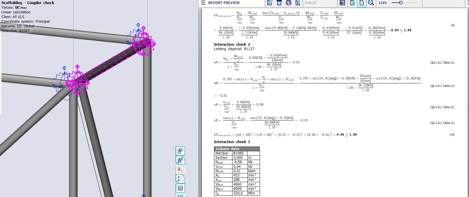
Improvement for Layher Interaction 2
In the past, a conservative method was applied: to sum all diagonal forces for the interaction 2 check. New information in the Zulassung revealed that it is sufficient to do each check per diagonal and store the max check.
The check in the program has been updated accordingly, showing the limiting diagonal and its corresponding check.
Better handling of zero resistances
Previously we modified the logic to have hard-coded zero values of resistances in case no data were given. When a non-zero force occurs in such a component, we set the check to 999. This prevented customers from running checks and providing their own proof for the inputted resistances.
In the new version the check is not set to 999 but a warning is issued instead. This way, users are informed about the non-checked component without having invalid checks.
Update of the Zulassung
The implemented Zulassung documents have been updated to the most recent versions.
Concrete 2nd order effect settings
SCIA Engineer calculates the second order effect for concrete columns according to all three methods described in EN 1992-1-1. The following methods are supported:
- Simplified method based on nominal stiffness, see EN 1992-1-1, clause 5.8.7.
- Simplified method based on nominal curvature, see EN 1992-1-1, clause 5.8.8.
- General method (a method based on geometrical and material nonlinearity of the member), EN1992-1-1, clause 5.8.6.
The method can be set in the concrete settings (the global setting) or in the concrete member data (the local setting). The method to be used (simplified or general) can be determined set manually or automatically according to the type of combinations and selected functionalities (concrete material nonlinearity, geometrical imperfections....).
Aside from this main change, version 24 adds the following other possibilities influencing on he calculation:
- The possibility to input coefficient (Coeffeff) for calculation of the effective creep ratio. This coefficient can be inputted in the concrete settings or in the concrete member data and can be calculated according to EN 1992-1-1, clause 5.8.4(2)
- The possibility to ignore the effective creep ratio for the calculation of the second order effect if the conditions in EN 1992-1-1, clause 5.8.4(4) are fulfilled.
- The effect of the imperfection is considered for the calculation of the end moments M01 and M02.
- The “c” parameters (factors depending on the curvature distribution) can be calculated automatically, inputted according to the shape of the curvature or inputted manually, see EN 1992-1-1, clause 5.8.8.2(4).
- The “co” parameters (coefficients which depend on the distribution of first order moment) can be calculated automatically, inputted according to the shape of first order moments or inputted manually, see EN 1992-1-1, clause 5.8.7.3(2).
All these changes result in a more economical design of slender columns and give more possibilities to change the input parameters of the calculation of second order effects.
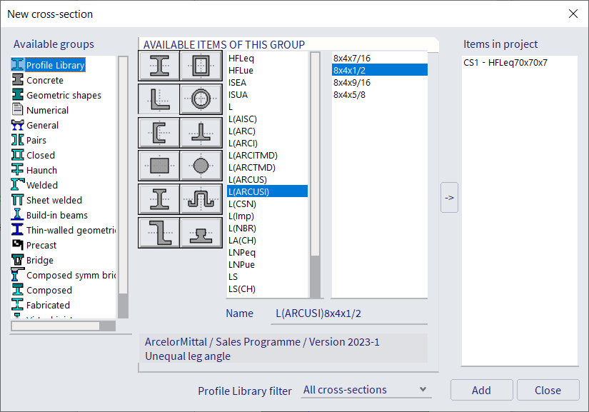
Arcelor Mittal catalogue update
The cross-section library has been updated with the 2023 Arcelor Mittal catalogue. Profiles have been added, adapted and their references updated.
The following cross-sections were updated:
- UPE(ARC)
- PFC(ARC)
- UPN
- L(ARCI)
- W(ARCUS)
- W(ARC)
- HP(ARCUS)
- HD(ARC)
- UBP
- UB(ARC)
- UC(ARC)
- HP(ARC)
- HL
- IPE
- HE
- J
- IPN
- S(ARC)
- C(ARC)
- MC(ARC)
- L(ARC)
- L(ARCUS)
- HG(GOST)
- UE(GOST)
And the following new cross-sections were added:
- HP(ARCUSMET)
- HLZ
- L(ARCUSI)
- WTM(ARCUS)
- R(ARC)
Also the webhelp for v24 containing all our library cross-sections has been updated.

Want to try SCIA ENGINEER yourself?
Explore how our software and services can help you optimise your work and boost your productivity. Try it for yourself with a free 30-day software trial.
Download a free 30-days full trial