Highlights
- Accurate design of rigid frame connections according to Eurocode 3, taking into account the simultaneous action of strong- and weak-axis bending, shear forces and axial forces on the connection.
- Intelligent automation of design code rules as well as of complementary publications that extend the scope to more joint configurations: for four bolts per row, for weak-axis bending, etc.
- An automatic update of joint stiffness based on derivations according to the component method.
- Verification of pinned connections, circular hollow section joints, bolted diagonals in a 3D design environment.
- Automatic generation of detail drawings for production or further elaboration in Picture Gallery or external CAD software.
- Expert System for fast selection of the right solution for the geometry and arrangement of the components in a steel connection.
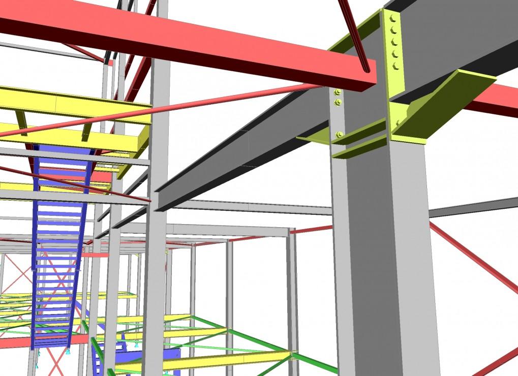
The module sensd.10 Steel connection design and drawings lets you model, visualise and design various steel connections. The following connection types are supported:
- rigid and semi-rigid connections in frames;
- rigid, semi-rigid and pinned column bases;
- pinned connections;
- hollow section joints between CHS sections
- bolted diagonals: open sections attached to gusset plates or directly attached to primary elements.
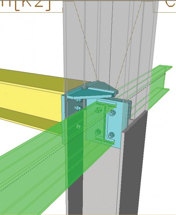
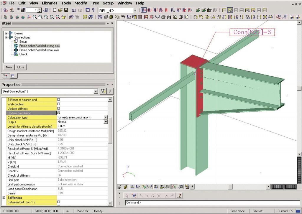
Rigid and semi-rigid connections in frames
This functionality applies the Component method for the calculation of resistance and stiffness of frame connections:
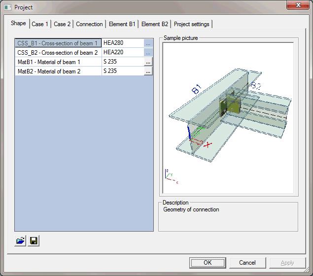
- Connections may be defined between symmetrical or asymmetrical I-profiles, and between I-section columns and RHS beams; the profiles can be hot-rolled and sheet-welded.
- Various joint configurations are supported -- girder-to-column knee-, cross-, single and double T-joints, splices (both bolted and welded) and base-plate connections.
- Beams may be connected to both the web and the flange of a column (strong and weak axis).
- Haunches, or a variable height of the connected members is also taken into account.
- Both a two-row and a four-row bolt configurations are supported, following the guidelines of "Joints in Steel Construction: Moment-resisting joints to Eurocode 3" (BCSA); bolts can be designed as standard or prestressed;
- The capacity and stiffness of each connection component, as well as the connection as a whole are calculated according to EN 1993-1-8:2005, or DIN 18800: 1990 Teil 1, or BS 5950-1:2000.
- Rigid and semi-rigid connections are checked for the effect of bending moments (around major and minor axis), shear forces and normal forces. Interaction with normal forces in the connected members is taken into account as prescribed in the code; interaction with weak-axis bending is based on complementary publications.
- CIDECT regulations are used for the design of column bases under RHS columns, and plate-to-plate splices of RHS elements: Design Guide for rectangular hollow sections (RHS) joints under predominantly static loading. CIDECT Köln (1992).
Modelling
- Bolt libraries are available, as well as concrete and anchor data for column bases.
- The following types of additional strengthening may be defined:
- Various haunches -- cut from T-profiles, I-profiles, made from welded plates, etc;
- Backing plates on the webs of beams and columns;
- Triangular and rectangular stiffeners placed opposite of the flanges of the connected member or diagonally.
- Clear contextual dialogues are provided for endplates, bolts, ribs, stiffeners, backing plates.
Checks
- All normative prescriptions are followed per component, including checks of resistances (of webs, flanges, stiffeners, bolts, welds), plate dimensions (pitch, gage, and edge distance) vs. bolt size, minimal weld sizes.
- National Annex specific rules are taken into account: e.g., the modification to the triangular limit rule in the French National Annex.
- Additional checks for practical feasibility are also performed (gap sizes vs. wrench size).
- Joint classification is performed by stiffness and by strength; ductility classes are determined.
- Although national codes and annexes are followed, many of the parameters are still editable (safety factors, parameters for bolt placement, slip and torque factors for pretensioned bolts, etc.).
Stiffness
- Based on the component method, moment-rotation diagrams per joint are derived and displayed in the report.
- The calculated joint stiffness is compared to the initially assumed in the analysis model; a warning is issued if the difference is outside the allowable limits.
- The calculated joint stiffness can be used to automatically update the analysis model with flexible joints (linear or nonlinear).
- The automated closed-loop workflow ensures a correct design with actual stiffness, preventing unexpected behaviours of the entire structure.
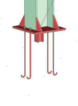
Column bases
For column base-plate connections specifically, besides haunches and stiffeners, the following types of strengthening are supported:
- Flange ribs (wideners);
- Shear keys (shear irons).
Anchors may be:
- straight or curved,
- plain or high-bond (ribbed or deformed) bars,
- with or without circular plates at their ends.
Column bases may be designed as pinned as well.
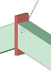
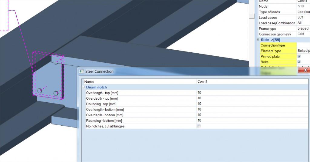
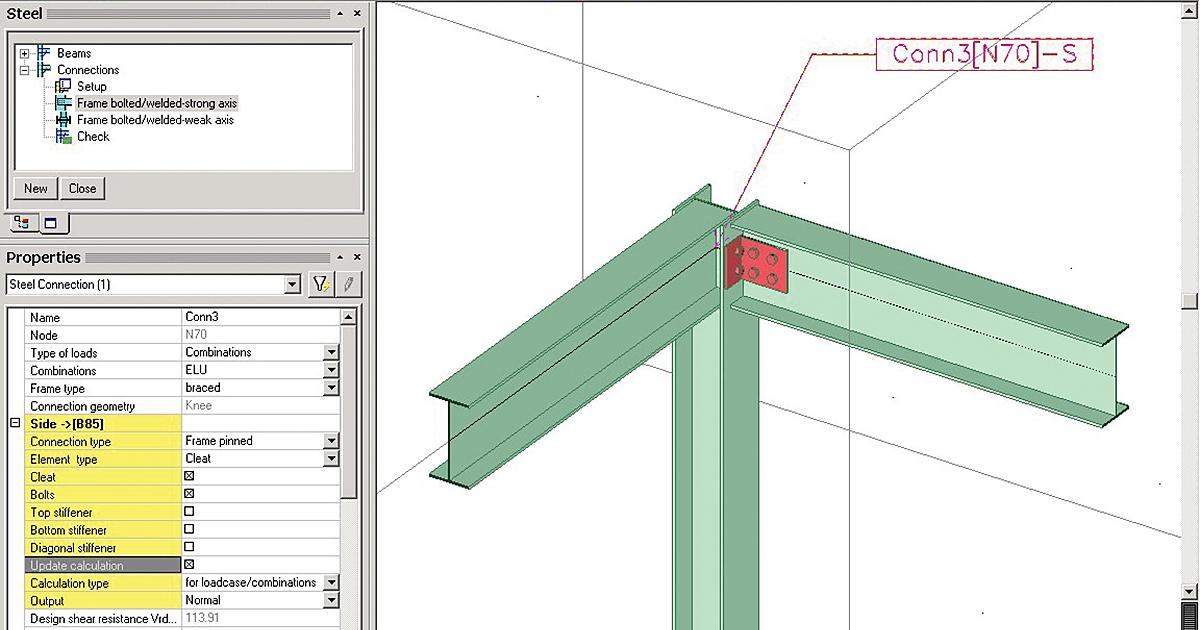
Pinned connections
This functionality applies the Component method for the calculation of hinged connection resistance:
- Single- and double-sided column-girder (knee, cross, single- and double-T) and beam-to-beam connections are supported.
- Beams may be connected to both the web and the flange of a column (strong and weak axis).
- The connections may be bolted and welded or combined (e.g., welded to one element and bolted to the other).
- The available connecting elements are fin plates, web cleats and short endplates.
- The design is executed according to EN 1993, or DIN 18800 T1, or BS 5950-1:2000.
- Normative prescriptions related to bolt spacing, edge distances and practical feasibility are followed.
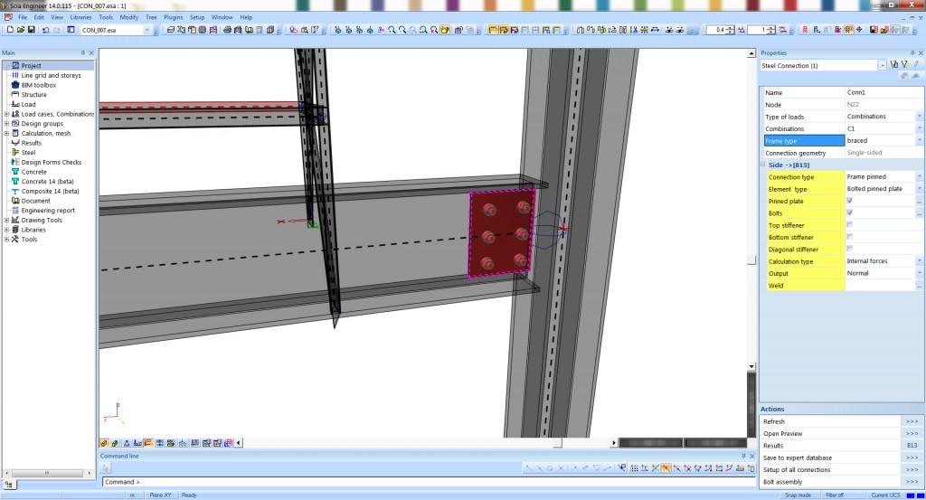
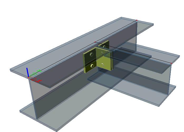
Modelling
- All elements of a connection, are visualised in the 3D scene, i.e., bolts, welds, cleats;
- Detailing and design is fast and simple via interactive dialogs.
- For beam-to-beam connections, notches may also be defined.
Checks
- Internal forces are recalculated from their FEM values at the nodes to obtain the values at the joint interface.
- Freedom in design is guaranteed by editable factors and coefficients.
- Predefined, user-editable data include partial safety factors, geometrical defaults, limits for the positioning of bolts - intermediate spacing, edge distances, minimal weld sizes;
- Bolted connections may be designed with snug-tight or pre-stressed bolts. Slip factors are automatically calculated for preloaded bolts. The necessary torque is mentioned in the calculation report;
- The limit states of the connection are evaluated according to the component method under shear and axial force. Required checks are performed in function of the connection layout.
- The different components of the connection are checked: beam web, column flange/web, additional connecting elements, bolts and welds.
Hollow section joints
This functionality checks welded connections between circular hollow sections (CHS) according to EN 1993-1-8:
- Uniplanar T-, Y-, N-, X-, K-, DX-, DY- joint configurations are supported; the joint configuration is automatically recognised from the modelled geometry and the member types defined via the Structural model.
- Connection parameters important for the design, like gaps and overlaps, may be determined directly from the Structural model, taking into account eccentricities defined there, or may be entered manually.
- The connections are checked according to the rules in Chapter 7 of the code, taking into account the interaction of all relevant internal forces in the joint (bending moments and axial forces).
Checks
- The applicability of the calculation method from Chapter 7 is checked in terms of joint geometry, material properties, profile thickness, section classes, sizes of gaps and overlaps.
- All relevant failure modes are checked: chord face failure, punching shear, brace failure.
- Additional moments resulting from eccentricities are taken into account in the design of compression chord members.
- Calculation of necessary weld sizes is done based on ECCS Technical committee 10 - Structural connections N° 126.
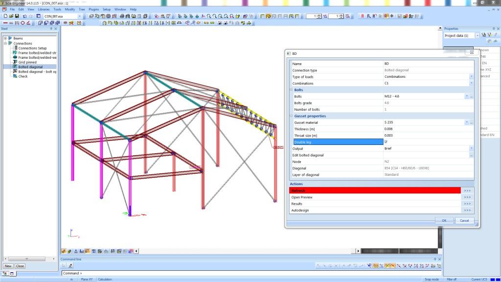
Bolted diagonals
This functionality checks the resistance of bolted diagonals (i.e., bracing, truss elements) according to EN 1993-1-8:
- The diagonals may be connected by means of a gusset plate or bolted directly onto a vertical element.
- The cross-section of the diagonal may be an angle, a channel, or an I-section.
- In the case of a direct connection to a vertical element (an angle or a cold-formed section) by a single bolt, the cross-section may be a cold-formed or an RHS section.
- Checks are performed on the resistance of the bracing element, bolts and gusset plates.
- Diagonals that are directly connected to a primary load bearing element are often found in tower masts and storage racks.
Modelling
- The diagonals are assumed to be attached to a gusset plate via bolts; gusset plates are assumed to be welded to the column.
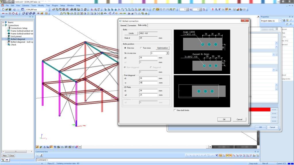
- The connection at the diagonal end is always bolted. One or two (non-)staggered bolt-rows may be used.
- The bolted diagonal functionality includes no 3D visualisation.
Verification and design
- Safety factors, default spacing requirements and minimal weld sizes are taken into account; these may also be modified
- The following checks are performed:
- bolt shear resistance,
- slip resistance in the case of slip-critical joints,
- resistance of connected elements against bearing,
- resistance of connected elements against rupture and (block-)shear in net sections,
- weld throat size between gusset plate and main supported element.
- Using automatic optimisation, the minimum required number of bolts may be determined.
- You may specify whether only tensile, or both tensile and compressive normal forces should be considered in the connection design;
Reporting
- Utilisation levels, critical load combinations are displayed in the Brief report; the limiting component in the designed connection is also indicated.
- A Detailed report describes all parts of the performed connection analysis with intermediate values and used parameters:
- The “Detailed connection drawing” wizard generates detailed dimensioned drawings for all parts of the connection in DWG format.
- The connection design report and drawings are available in the Engineering Report;
Expert system
This functionality is an intelligent database for a quick selection of a suitable configuration for a steel connection.
- Skipping the modelling step entirely, the Expert System proposes possible joint layouts: end plates, bolt layout, stiffeners, which fit geometrically and fulfil the condition
- of utilisation.
- The solutions are adequate to the assigned cross-sections, to the angles between members (even when haunches are present) and to the present internal forces.
- You may specify preferences on bolt classes, orientation of endplates and haunches, and assign priority to the individual items in the database. This allows for a certain level of standardisation over multiple projects.
- After you select one of the proposed configurations, all connection components are immediately assigned to the joint and the exact bearing capacity and stiffness are calculated.
- The functionality is applicable to rigid, semi-rigid, or pinned frame connections.
- The library contains solutions from a number of connection design books:
- Steel moment connections according to Eurocode 3. Simple design aids for rigid and semi-rigid joints, Sprint Contract RA351;
- Bemessungshilfen für nachgiebige Stahlknoten mit Stirnplattenanschlüssen, Ernst and Sohn Berlin, DSTV;
- Bemessungshilfen für profilorientiertes Konstruieren, Stahlbau-Verlagsgesellschaft mbH Köln, Stahlbau Kalender.
- In addition, internally developed complementary sets have been added by SCIA, including haunched types.
- You may also extend the database with your own preferred connections, or they may filter connection proposals based on the source: e.g., only BauKalender, or only user-defined.
- Experienced designers app
- reciate the ease of use, automated workflow, and possibility to store their own connection designs for future use.
Connection drawings
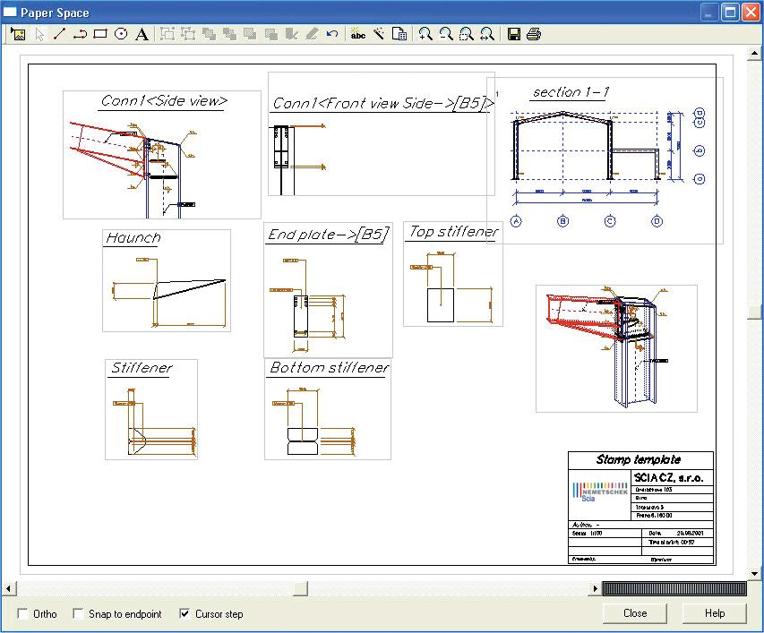
Detail drawings may be generated automatically for all or selected steel connections in the model.
- These contain information about endplates, stiffeners, welds, dimensions, etc. and can be edited and elaborated with, among other things, text and additional dimensions.
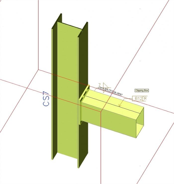
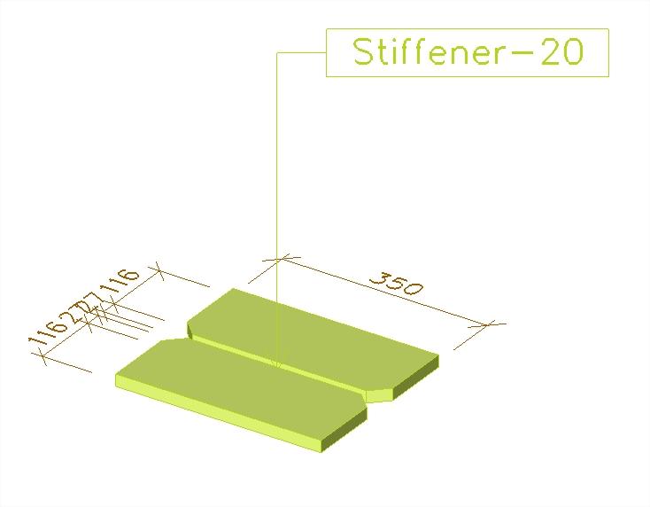
- The connection may be shown in 2D or 3D from any selected viewpoint; beside front/side view of the whole connections, individual components like endplates and stiffeners are drawn.
- Weld symbols are according to ISO 2553; the user may select to not have these on the drawings and replace them with another mark-up.
- Scales, character sets, fonts, font sizes and clipping volume are user-defined.
- The drawings may be inserted into the final drawing layout in the PaperSpace Gallery; there, these can be combined with the General arrangement drawings (module sendt.01):
Required modules:
- sen.00