The revolutionary new interface with leading-edge ergonomics and unequalled efficiency gains presented in SCIA Engineer 21 has been further fine tuned to make your work even faster and easier. SCIA Engineer 21.1 comes with a brand-new marking menu as well as a broad collection of other improvements, extensions and updates:
- Marking menu
- Input table & Results table
- Preview
- Thickness of slabs
- Advanced modelling of cables
- Connection forces
- Design of reinforcement on integration member
- Design of multi-layer reinforcement
- Design of composite column
- Default bow-imperfection input for concrete
- IDEA StatiCa Checkbot link
- SAF 2.0
- BIMCloud update for Archicad users
Marking menu
The Marking menu is a brand-new feature presented in the new user interface in version 21.1 and it is a true productivity booster. It is an invisible radial menu that allows for rapid modelling of the most frequently used commands without the need to move the mouse cursor anywhere from its current location. The menu will appear on demand at the very spot, where the cursor is. Just hold Alt key and right the mouse button to display it.
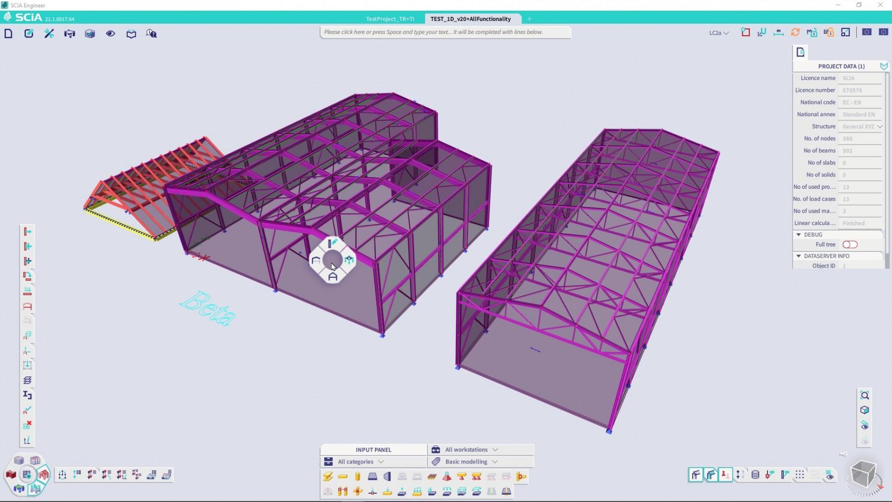
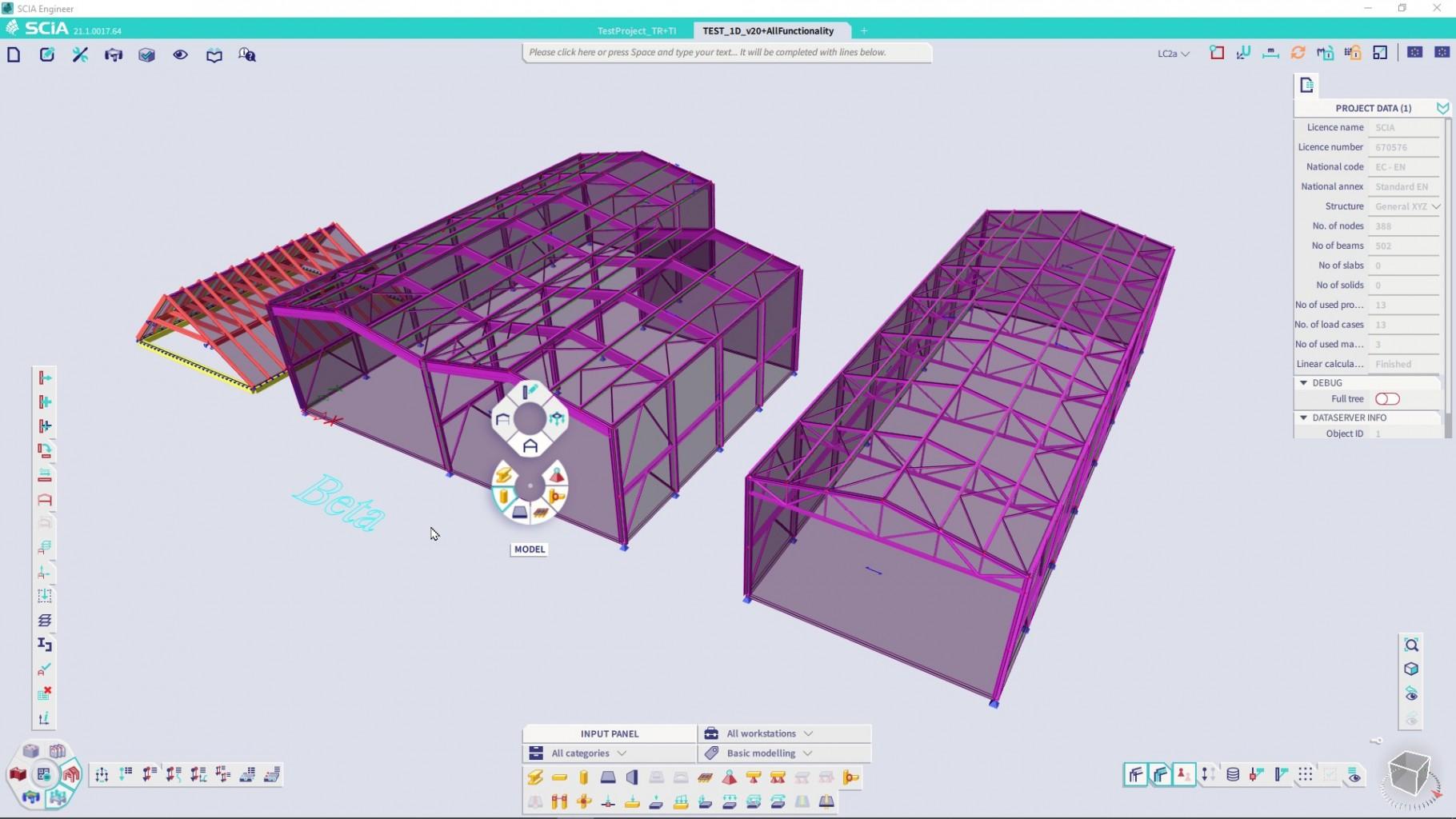
The Marking menu has 4 basic segments: Model, Loads, Modify and Visibility and under each segment you will find the most often used commands logically ordered.
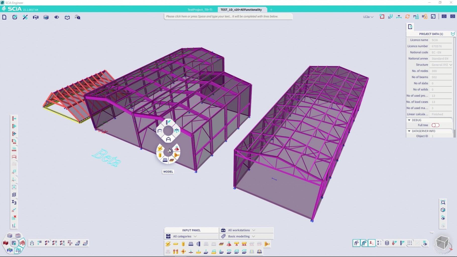
You may navigate through the menu simply just by moving your mouse in the chosen direction while still holding the right mouse button. The running of command does not require any precise click – just move the mouse in the direction of the command and release the right mouse button to run it.
Once the command starts, the menu disappears, but it is always ready to be opened again, shall you need it. The Marking menu is easy to access and contains a fixed list of commands, which helps to build a muscle memory while using it. After a few minutes, you will surely remember the commands you use the most and since that moment these can be reached very, very rapidly.
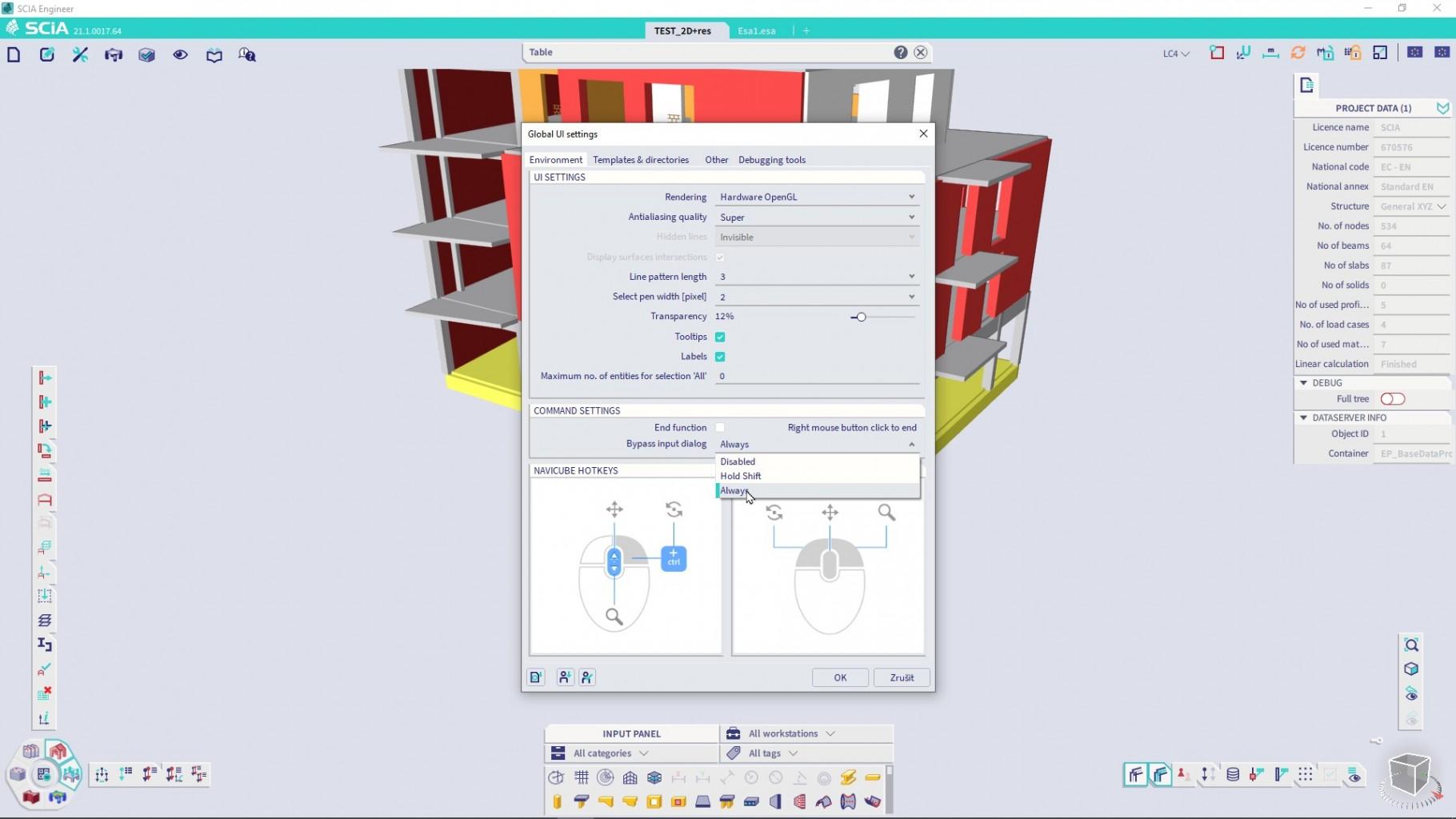
You can also use the Marking menu in a combination with bypassing the input dialogs, and you will still keep the full control over your modelling as all the inputted data are shown in the Propertied panel. Therefore, consider turning the “Bypass the input dialog” option to “Always” in the Global UI settings to get the full productivity advantage that SCIA Engineer can offer.
Input table and Results table
Input table and Results table are 2 new components in the new transformed user interface in version 21.1 that are inspired by the Table input and Table results from the old user interface. Both components can be opened thorough the “Tools” menu. Alternatively, writing “table” in SCIA Spotlight will allow you to display these components without any manual searching. You may also assign a suitable hotkey to these components. “I” for Input table and “R” for results table suggest themselves as one of relevant options.
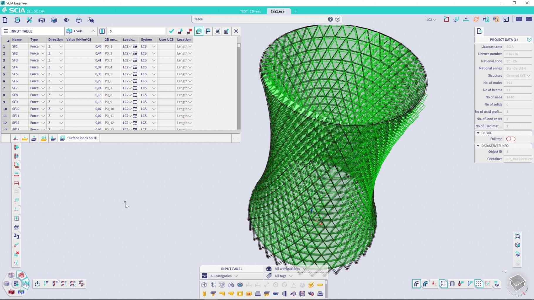
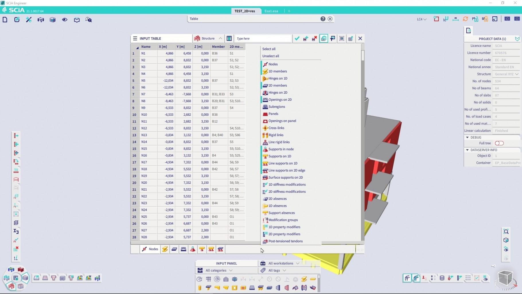
The Input table displays tabular representation of the model.
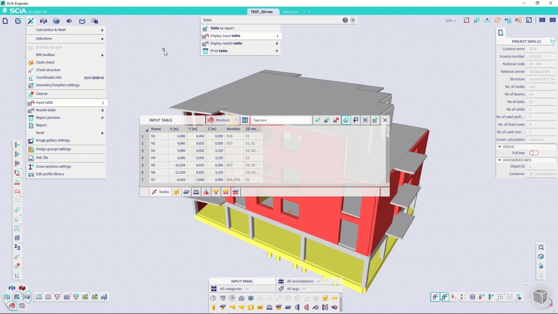
The Input table has 3 parts: Header, Table and Footer (Tabs).
The Header part contains:
- Label of the table. This is the area on the top left of the table that may be used to position the component on the screen or to minimize it. The Tables may be moved out of the main application window onto a second monitor.
- Workstation selection: All available tables are divided into 3 workstations: Structural elements, Loads and Libraries. You may choose which area you want to see or edit in the drop-down menu on the header of the panel.
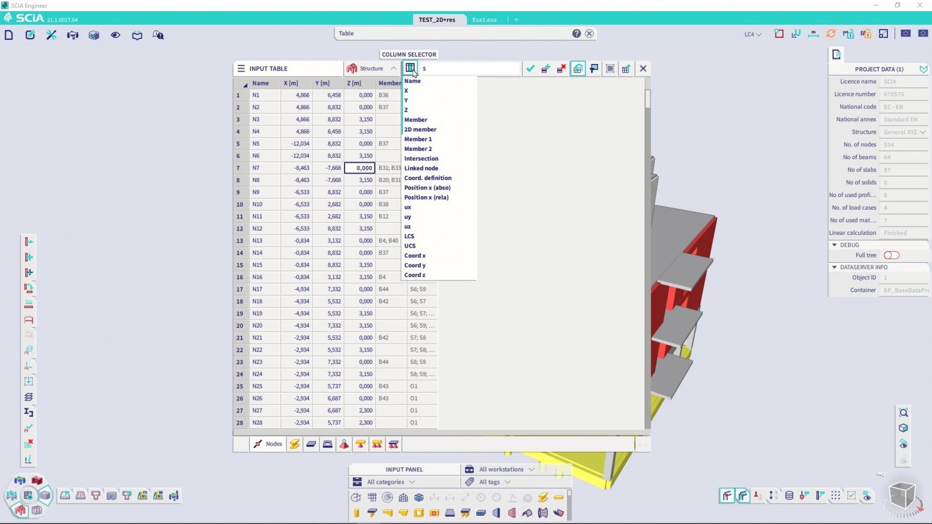
- Column selector: You may choose which columns are important for you in each table. By default, only the most important columns are shown, but each object type may contain additional data.
- Multiple edit box: You may assign a value to multiple cells at the same time. The cells is selected simply by mouse and Ctrl or Shift keys. Using these keys and mouse any selection may be done and all the data may be changed at once by assigning a single value.
- Data filters. You may either display all data lines or filter them to show only visible objects or only selected objects.
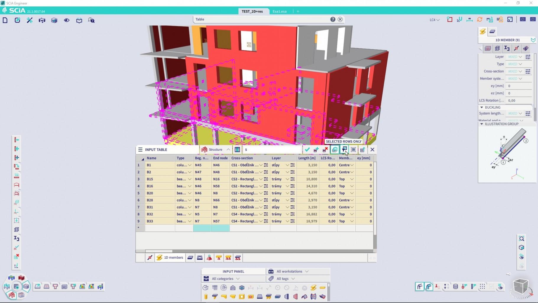
- You may also send the content of the table to the Engineering Report if it is important for the final documentation of your project.
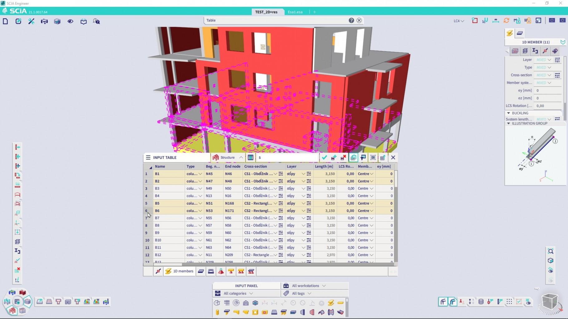
The body of the table contains the data. These are in most cases editable directly in the table. You may just click on an editable cell and change the value. To change multiple values simultaneously, you may use the multiple edit box (see above). The table body has additional features, such as:
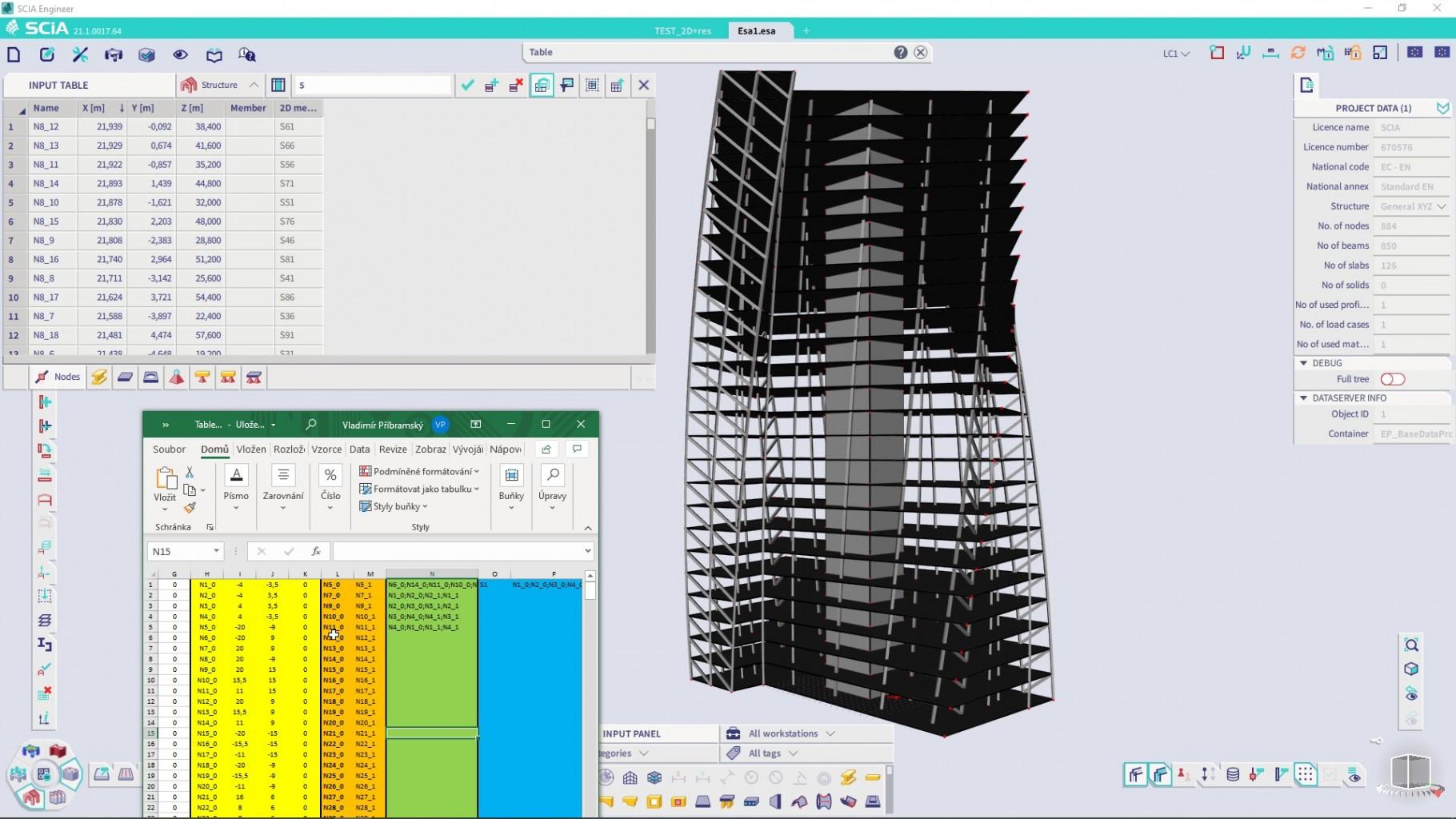
- Working with selections: You may select cells and copy their content from the current table and paste the values to MS Excel. This works for both Input table and Results table. Just use Ctrl+A while you have your mouse cursor over the table to select all (or make any rectangular custom selection by using Shift key) and Ctrl+C to copy the selection. You may paste updated data from Excel back into the Input table to change the structure.
- Sorting the values in a selected column. Simply click on the header of any column and the data will get sorted: from smallest to largest, the opposite direction or alphabetically.
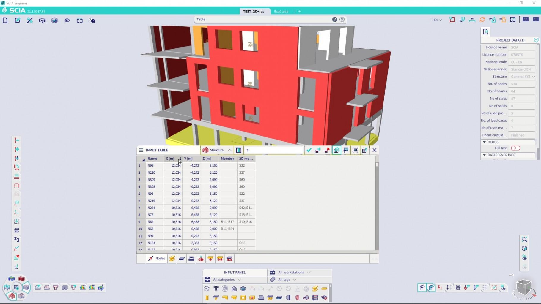
- Selecting structural objects is simple. Click on any line header. Lines, that correspond to the selected object are highlighted in yellow.
- You may also import new objects or update existing by pasting data from MS Excel. This procedure may be used to modify existing objects or create multiple new ones in a single step, which is a form of parametric modelling based on Excel spreadsheet. This approach gives you full flexibility in modelling and there is no limit on the amount of data imported this way. You may create just anything this way, from a skyscraper to complex shapes or complex loading on a cylindrical shell.
At the footer of the table, there are multiple Tabs available. The tabs that you see when you open the Input table are not all that are support, only the most important ones. You may choose more by right clicking in the tab area. Vast majority of the available types of objects available in the SCIA Engineer are supported here. Tabs may be reordered or hidden by dragging.
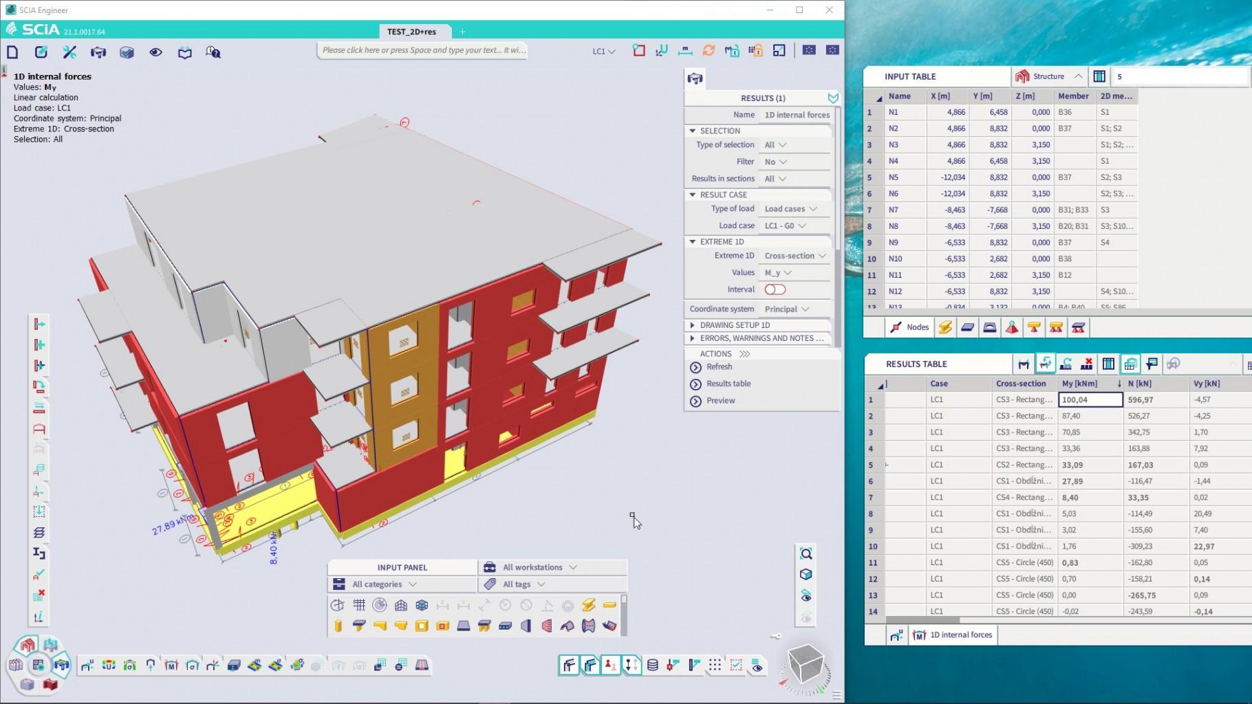
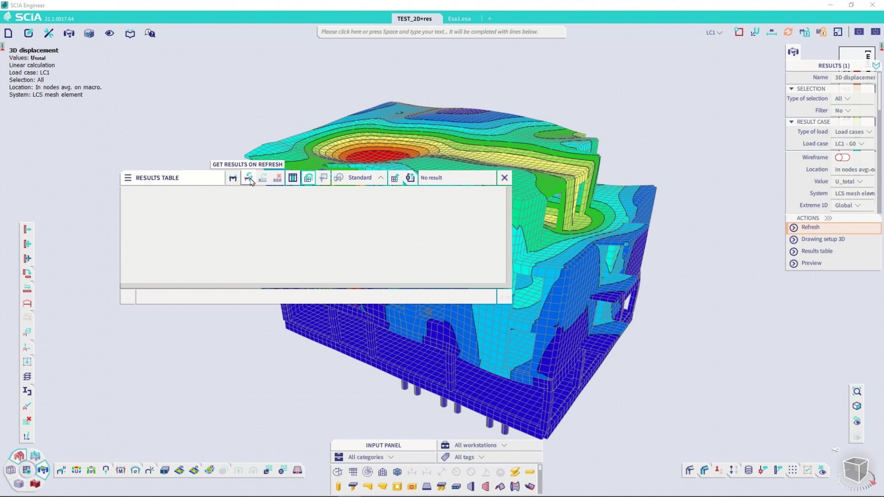
Results table has many similarities with the Input table. It has a header with a label and separate functions, a table body and a footer with individual result tables that were loaded into it. You can find the Results table either in the menu or through SCIA Spotlight or you may open it after accessing any results or checks using the “Results table” action button in the Properties panel.
When the table is opened, it is empty, as no data are loaded to the Results table by default. This is to prevent unwanted growth of the data because all loaded results are stored with the project when it is saved. You may use either action button “Results table” in the properties panel or use the button “Get results” in the Results table in order to get the currently opened results in the Results table. To get an additional table in the Result table every time you use the “Refresh” button in the Properties panel, enable the “Get results on refresh” toggle.
Similarly to the Input table, you may sort the data in the Results table by a selected column and you may also select specific lines in order to select structural objects on which the Results or checks are shown. If you no longer need any data in the Results table, you may move the corresponding tabs to the Trash that is activated whenever a tab in the footer is dragged. This works the same way as in the Input table. Alternatively, you may “Delete all tabs” with a button in the header. The benefit of the Results table is, that the results in the tables remain unchanged even after the structure has been modified and the results either lost or recalculated. This way you can easily evaluate the effect of the changes by simply comparing the results tabs created before and after the change. You may always refresh the tab using the “regenerate current tab” button, which will load the current data into the table.

You may use filters by visibility or selection to scrutinise the results and focus only on a subset of all members. Using other functions on the right side of the header, you can Export all data to MS Excel or to send required tables to the Engineering report.
The Results table may be used to evaluate checked elements further. By double clicking on any cell or by clicking on the “Detailed check to preview” button, the corresponding section of the element is highlighted in the 3D scene and a detailed check is opened in the Preview that is automatically opened.
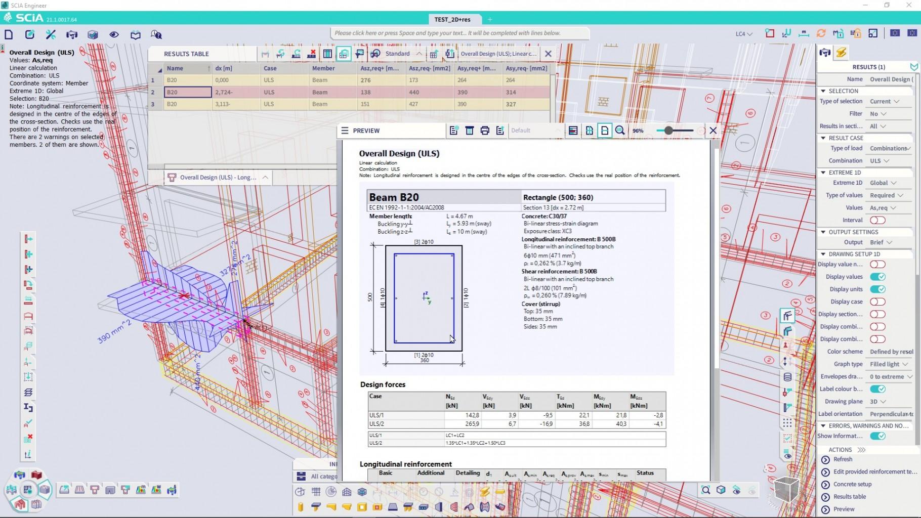
This workflow allows you to check any section in your structure quickly and in a great detail to help you understand how the value of the check was obtained and where exactly is this section located in the 3D model.
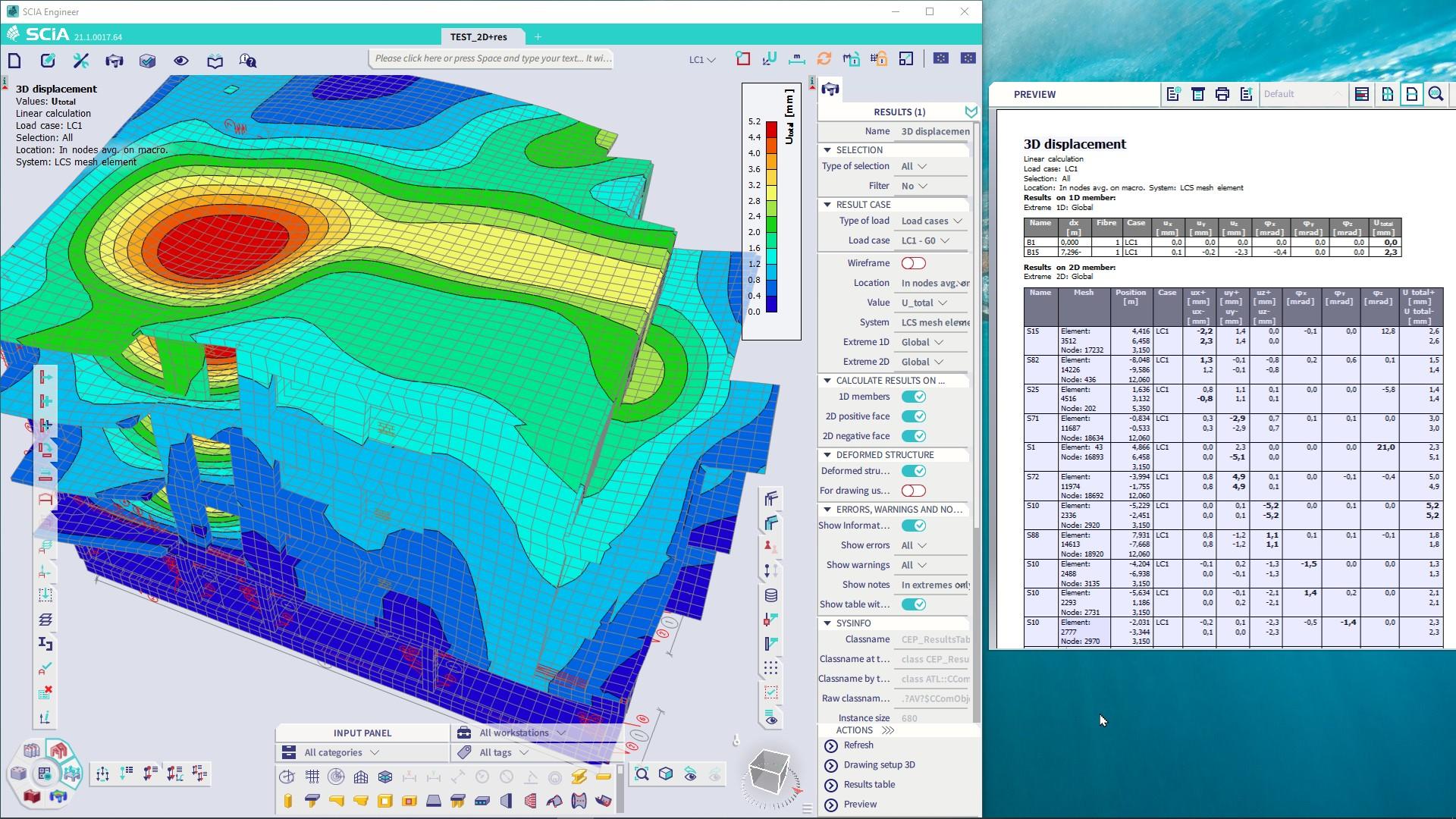
Preview
The Report preview has become in version 21.1 a native component of the new user interface and its overall visual style is aligned with other components like Properties panel or Input or Results table. The report preview may be displayed through the main menu, using a context menu of the 3D scene or via SCIA Spotlight as a “Print table” command. If you want to use for results or checks, it may be activated also from the Property panel action button which is available for any Result or Check command.
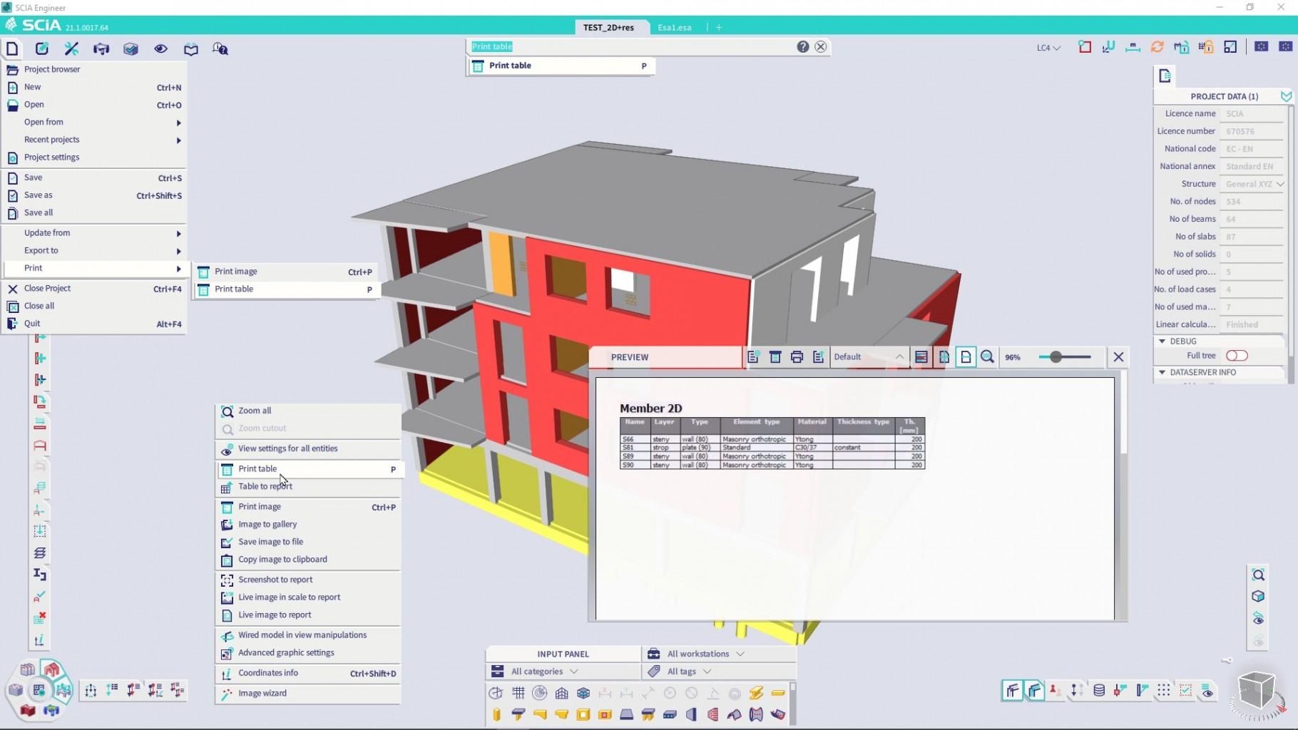
The report preview can show data of structural elements in the selection or to display Results and Checks in tabular or detailed way. It supports all the graphical features of output formats. You may send the document from preview directly to any available printer, you may zoom and scroll or apply different styles for the output. You may also send the tables directly to the Engineering report to compose the final documentation.
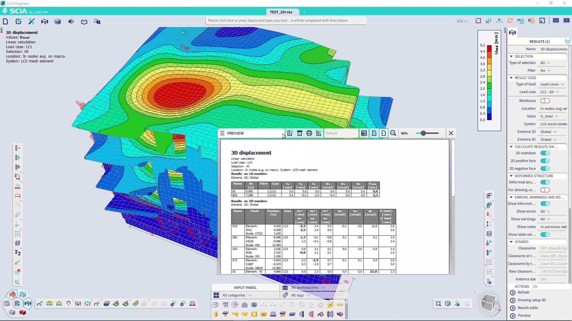
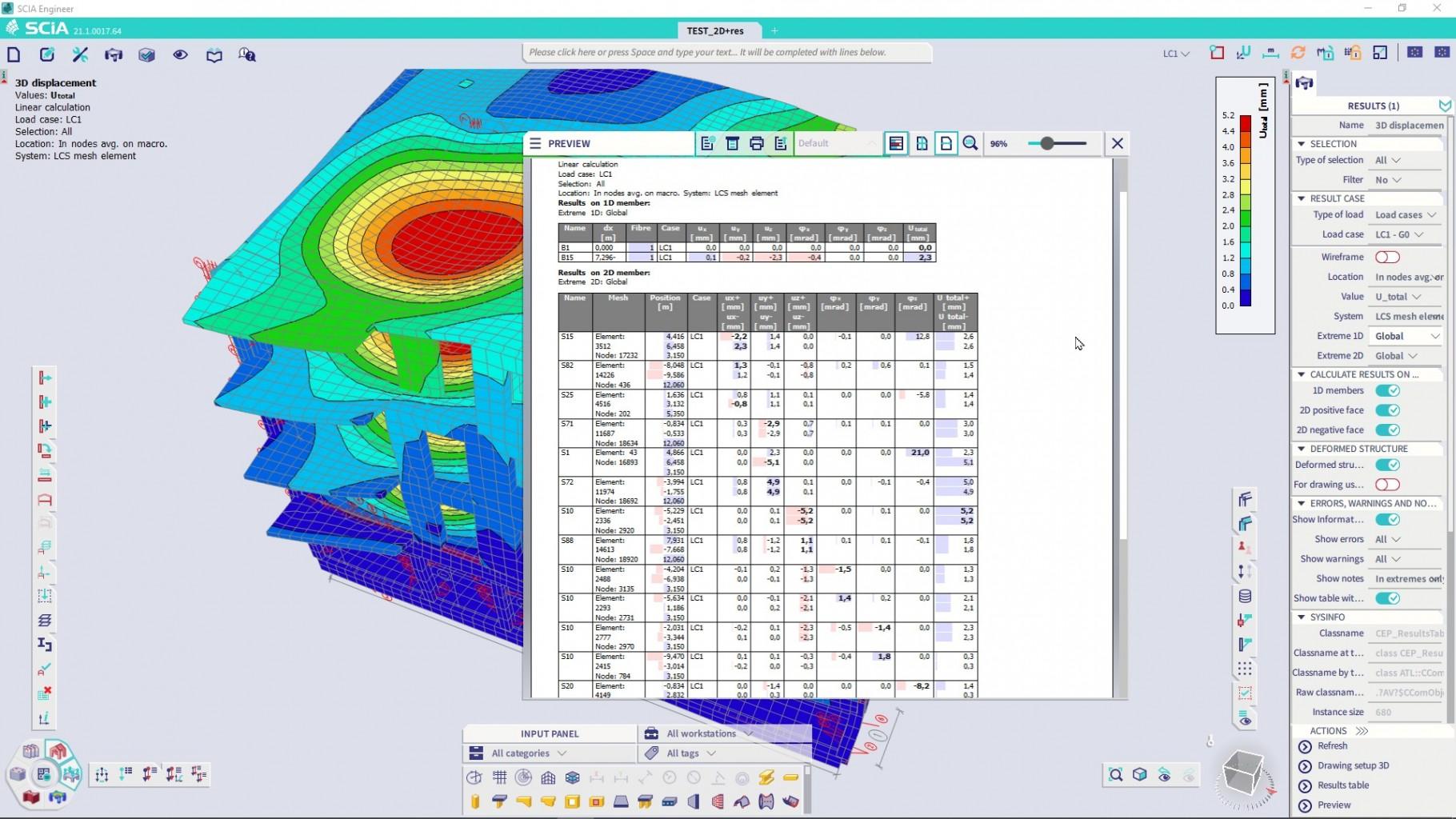
The Preview window has inherited features of other user interface components. It may be minimized within the application window, it can be anchored or docked.
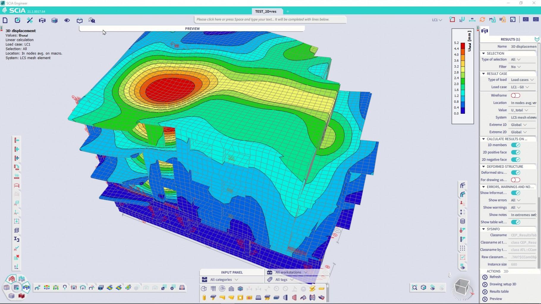
Alternatively, the preview window may be moved out of the application window and be placed on a second monitor so that it is always available, but not blocking the view of the structure.
Thickness of slabs
Version 21.1 features reworked possibility to display graphically the thicknesses of 2D members. The main benefit is that you are now able to produce clear and readable images where the distribution of material in 2D elements is apparent. This feature may be used to check the correctness of the inputted data without the necessity to manually select elements and check their properties. You will find the command “Thickness of slabs” in the Process toolbar in the “Results” workstation. You may also find it in the main menu or via SCIA Spotlight.
Using the “Thickness of slabs” function is most beneficial for project with concrete and masonry, but it may be very helpful also in the case of massive steel structures, where steel members would be represented by 2D elements. To offer full flexibility, selections and filtering are supported to show data only on a part of the structure.

We improved the presentation of the legend. The discrete legend is now used, which results in much clearer values. Only if a selection contains elements with varying thicknesses or if an excessive number of elements with different thicknesses are shown, a “smooth” legend is used.
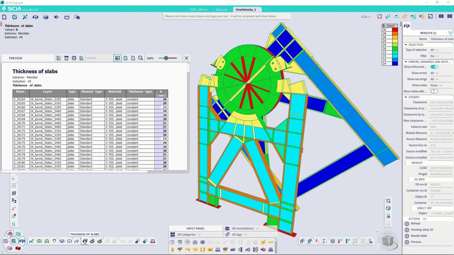
The images and tables can be simply used in the Engineering report.
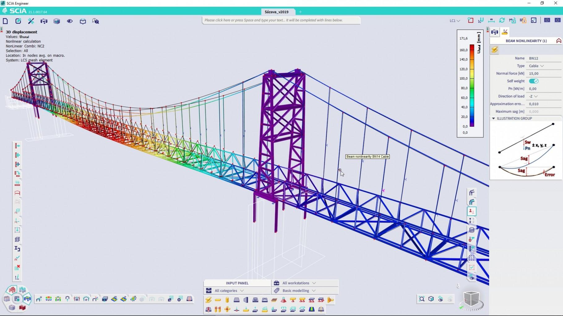
Advanced modelling of cables
Version 21.1 offers an enhanced pre-processing engine for improved modelling of cables. “Cable” is a type of nonlinearity that may be assigned to selected members to prescribe a tensile-only behaviour with a substantial initial deformation that are therefore calculated by 3rd order calculation. Typical structures where cables are used are cable stayed or suspension bridges, light-weight roofs of stadiums or other buildings which have usually great architectural value. Modelling of such structures is often very challenging and we made sure to make the modelling as convenient and fast as possible.
In version 21.1, the input of cables has been completely reworked, with the biggest change being the pre-processor. When the cable-type nonlinearity is inputted on a beam, its initial deformation is calculated analytically based on its self-weight, estimated applied load and prestressing force, and the cable shape is approximated by a polygon based on catenary curve. A catenary curve is an analytical solution for calculation of the displacement of a cable. This pre-calculation is done automatically even without running the FE analysis.
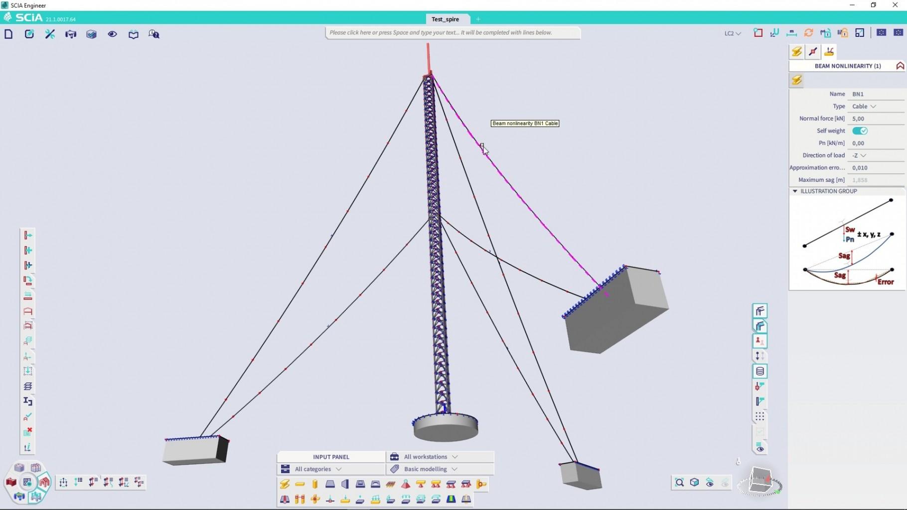
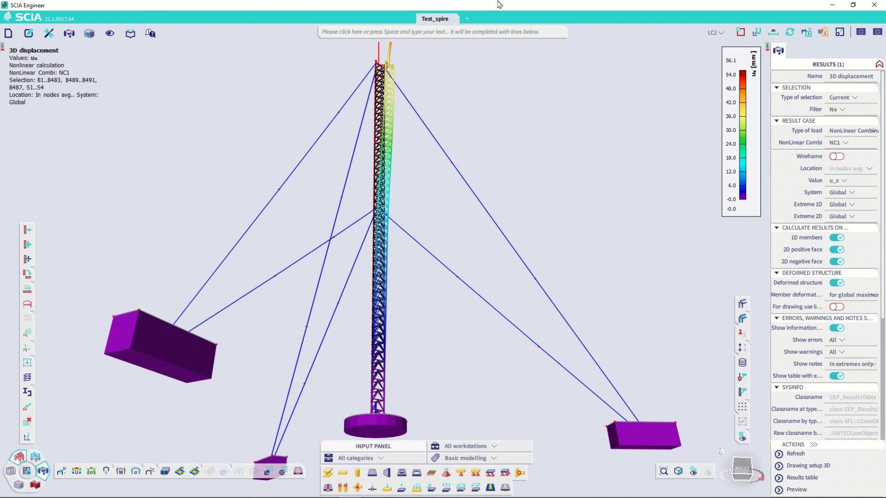
As the shape of a beam with defined cable behaviour is directly updated in the model, new interpolated nodes are available, and you may either connect additional cables or beams to these nodes or use snapping points and internal nodes along the length of the cable. This allows for endless possibilities of modelling of both simple and complex cable structures.
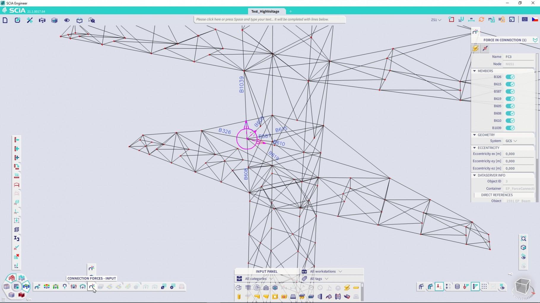
Connection forces
The “Connection forces” function is useful to get all the forces in a selected node where multiple beams connect. Before you can design a connection, forces per each beam need to be reviewed. Version 21.1 presents an enhanced workflow for getting these forces from the model. First, you need to add the “Connection force – input” to the required structural nodes. The command is on the Process toolbar in the “Results” workstation. After that you may select, which beams connected to this node you need to evaluate. By default, all are selected as this is the most convenient option in most cases.
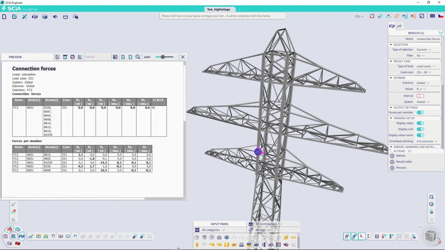
When a connection is defined, you may use the “Connection forces – Results” command to review the forces in the connection. The results are shown in two tables. The first one is a sum of forces in the connection, which will be zero, when all the beams are selected. The second table shows the forces in the coordinate system of the connection for each separate beam. You may use these values as an input for a 3rd party check (e.g., in an Excel spreadsheet) to design the connection or simply to pre-evaluate the connection based on your experience before starting its detailed design in SCIA Engineer or e.g., IDEA StatiCa Connection.
Design of reinforcement on integration member
The 'Integration member' is a virtual member without any stiffness, which can be freely arranged in the model. It is used for a spatial integration of 1D and 2D stresses from the relevant/selected members to show resulting internal forces as if they were on a single beam. The SCIA Engineer 21.1 further enhances this functionality allowing for the design of reinforcement on integration members to handle structural elements like lintels above openings, connections between split-level slabs or core walls.
The properties of the integration member have been extended so that you can now input information about the cross-section, member type, or buckling. With those parameters defined, the integration member is ready to proceed with reinforcement design using the standard workflow known from concrete beams and columns. You can choose whether a global Concrete setting is considered or overwrite some design/calculation parameters individually per member by adding Concrete member data. This step may include assigning a design template of provided reinforcement to allow calculation of not just theoretical required areas but also practical rebars for the supported type of cross-sections like T or L shape.
Currently, only automated input of reinforcement on integration members is available. By simple run of the reinforcement design command for a given load combination, you can get the results about suitable reinforcement first in the graphical or numerical output. When you are satisfied with the results, you can convert the provided reinforcement to real physical bars, edit them if necessary and check the final reinforcement with all the available concrete checks for both ULS and SLS design situations. Finally, you can include the reinforcement from integration members to a bill of material or export the reinforcement via XML or other formats.

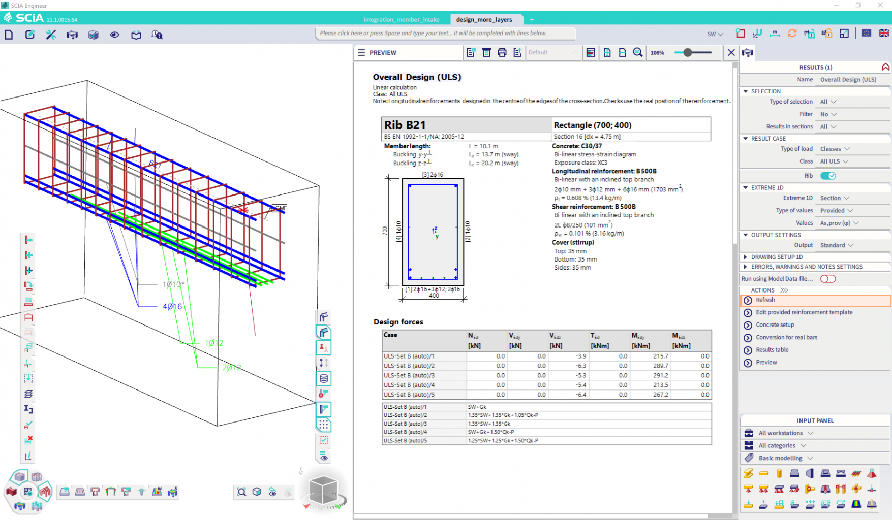
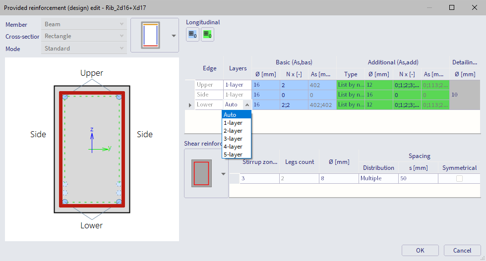
Design of multi-layer reinforcement on 1D members
The previous single-layer reinforcement design of concrete beams and columns could sometimes fail because of exceeding the limit spacing between bars in the layer. This release provides a new capability to design reinforcement in more layers to achieve a satisfactory arrangement of rebars for such cases. It also gives engineers larger flexibility to optimize the reinforcement distribution in situations like crack control, where using more bars with smaller diameters might be better.
The new capability of multi-layer design is currently applicable for rectangle, L-shape, and T-shape sections on beams. For columns, only the rectangle section is supported. The number of layers can be specified in a design template of the provided reinforcement independently per selected edge. Moreover, it's possible to choose 'Auto' mode instead, where adding reinforcement layers is automatically controlled by the program itself to find an optimal arrangement for the given assumption of basic and additional bars.
The designed reinforcement in more layers is possible to convert to practical rebars, edit them if necessary, and check the final reinforcement with all the available concrete checks for both ULS and SLS design situations. The real position of reinforcement layers is always taken into account.
Design of composite column
As our migration to a full 64-bit version of SCIA Engineer continues, version 21.1 brings you a brand-new service for composite column design. The functionality has been completely revised and of course migrated into the 64-bit version of the software. The service now enables an easy, accurate and detailed design of all composite column types described for verification in Eurocode EN 1994.
What does the new composite column check offer?
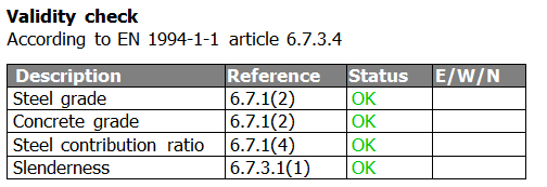
The check starts with a validity check, verifying whether the calculation rules in the Eurocodes can be applied to the selected column. A simple and clear overview table shows the status of each check.
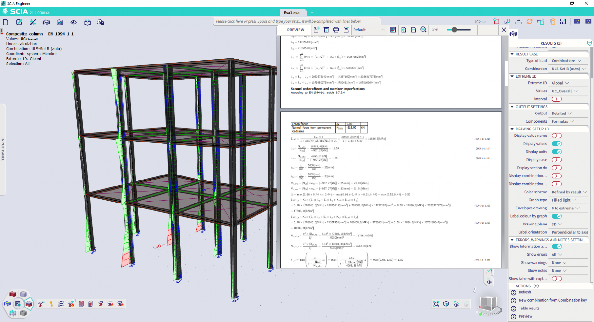
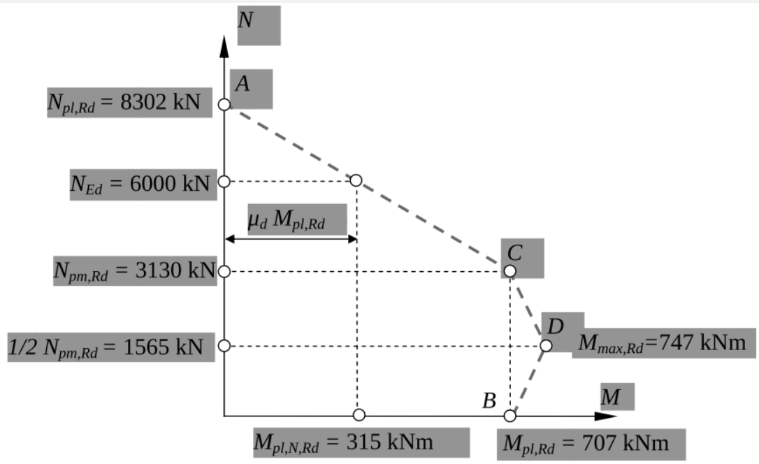
For the verification of combined bending and compression an exact calculation of the interaction curve is executed, going beyond the simplified determination methods given in the code. The pictures below compare the simplified approach from the code and the full calculation in SCIA Engineer. Important to note is that the exact calculation offers some additional capacity compared to the linear simplification, which results in a more economical design. A second benefit is that this allows handling cross-section types that are not described in the simplification.
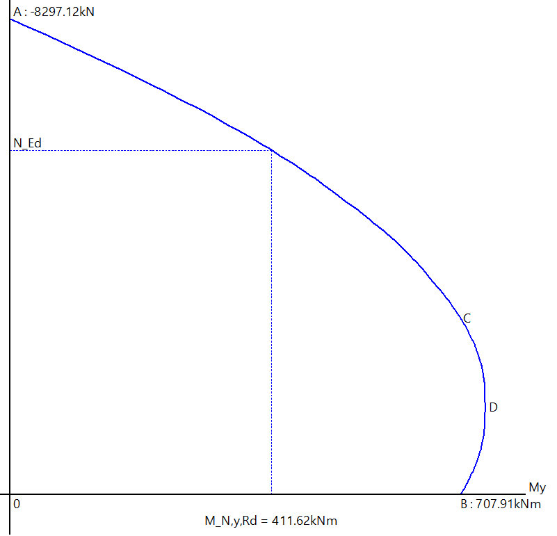
The graph of the interaction check is displayed in the brand-new detailed output for the check. There is also an option to display every used formula with filled in values and references to their corresponding chapters in the Eurocode 4. This means the check is fully transparent and the user can verify where every single value in the check is coming from.
For columns under pure compression, the user has an option to either verify them according to the European buckling curves, or to treat them like columns with combined bending and compression through the interaction curves. For the latter, SCIA Engineer also automatically evaluates whether additional bending moments are required due to second order effects.
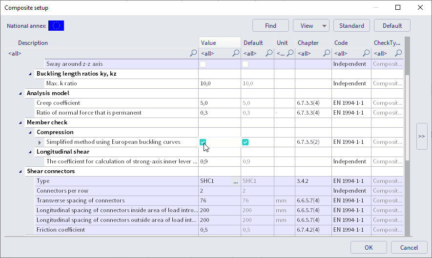
Furthermore, the positive effect of concrete confinement inside tubes is accounted for and also the longitudinal shear check has been extended beyond the scope of the Eurocode itself. All these improvements and extensions have been thoroughly checked and validated against published benchmarks that can be found in SCIA Engineer help.
Finally, it is not only the checks themselves that were updated. The effective flexural stiffness of the composite column accounting for reinforcement and long-term effects is now automatically taken into account in the calculation of the structure.
Summary and benefits:
- An exact calculation of the interaction curve is performed, going beyond the simplified determination methods given in the code. This allows for handling cross-sections that are not described in the simplification and it also leads to overall more economical design results.
- A detailed transparent output with formulas shows every step of the calculation and allows the user to verify every number. The advanced interaction curve is also graphically displayed in the output for an easy visual interpretation of the results.
- The effective flexural stiffness of the composite column, accounting for reinforcement and long-term effects, is automatically used in the calculation.
- For columns under compression both the approach according to the European buckling curves and according to the interaction diagrams are integrated in the check.
- The check for longitudinal shear has been extended beyond the simplified representations of the code.
- The positive effect of confinement of concrete inside tubes is correctly accounted for.
- The composite column design fully supports second order calculations.
- All the results of the composite column check have been thoroughly checked and verified against available benchmarks. Their details and explanations of possible differences can be found in the online help.
Default bow imperfection input for concrete
Version 21 brought you a fast and easy way to adapt the bow imperfections for all timber, aluminum, steel and/or composite members at once with a new handy default in the material setup. In version 21.1 this default setting has also been extended to the last remaining material: concrete.
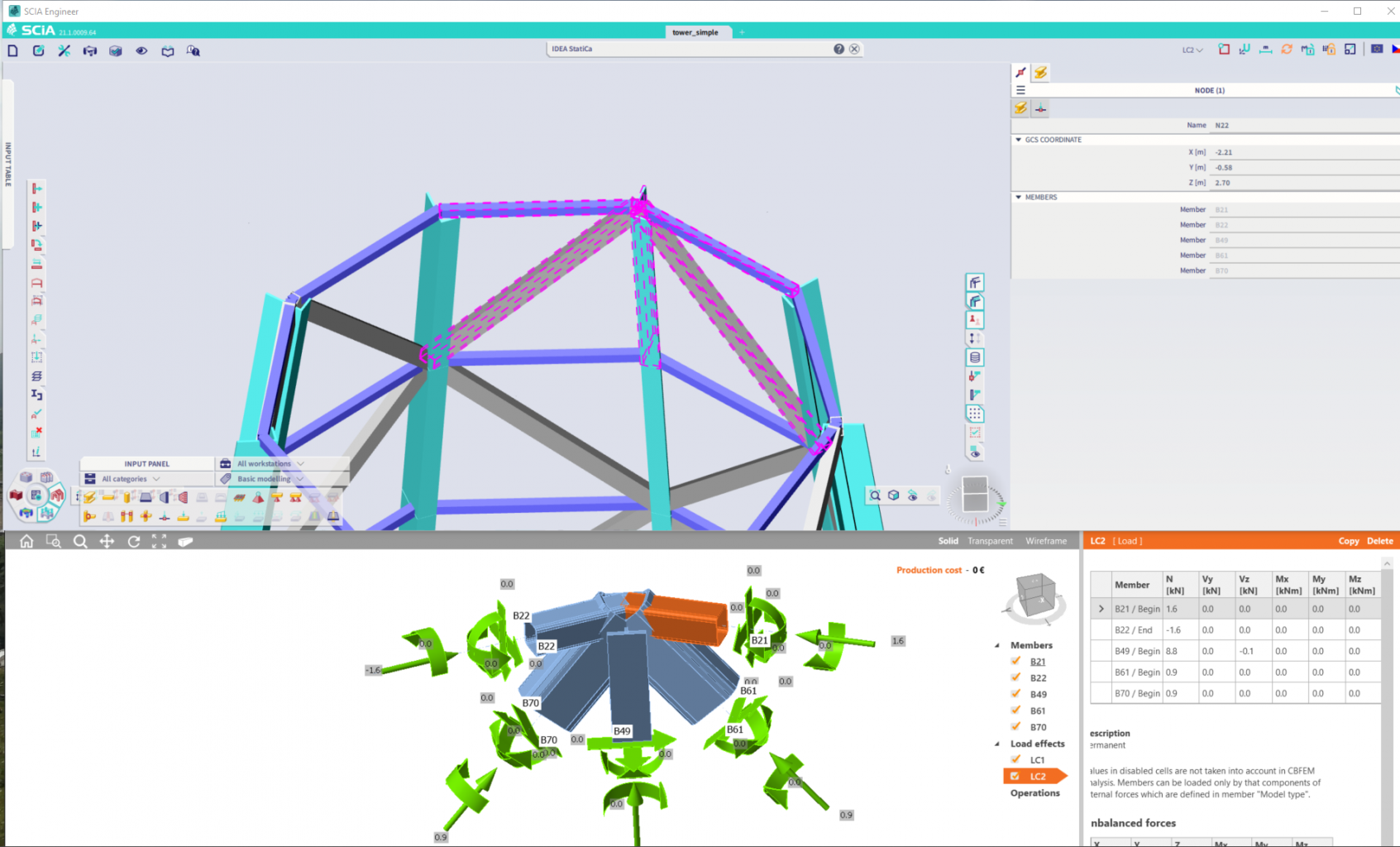
IDEA StatiCa link
SCIA Engineer 21. 1 introduces an updated link between SCIA Engineer and IDEA StatiCa with extended functionality. This updated link provides for the design and check of steel connections in IDEA StatiCa Connection and also for the check of whole steel members in IDEA StatiCa Member application.
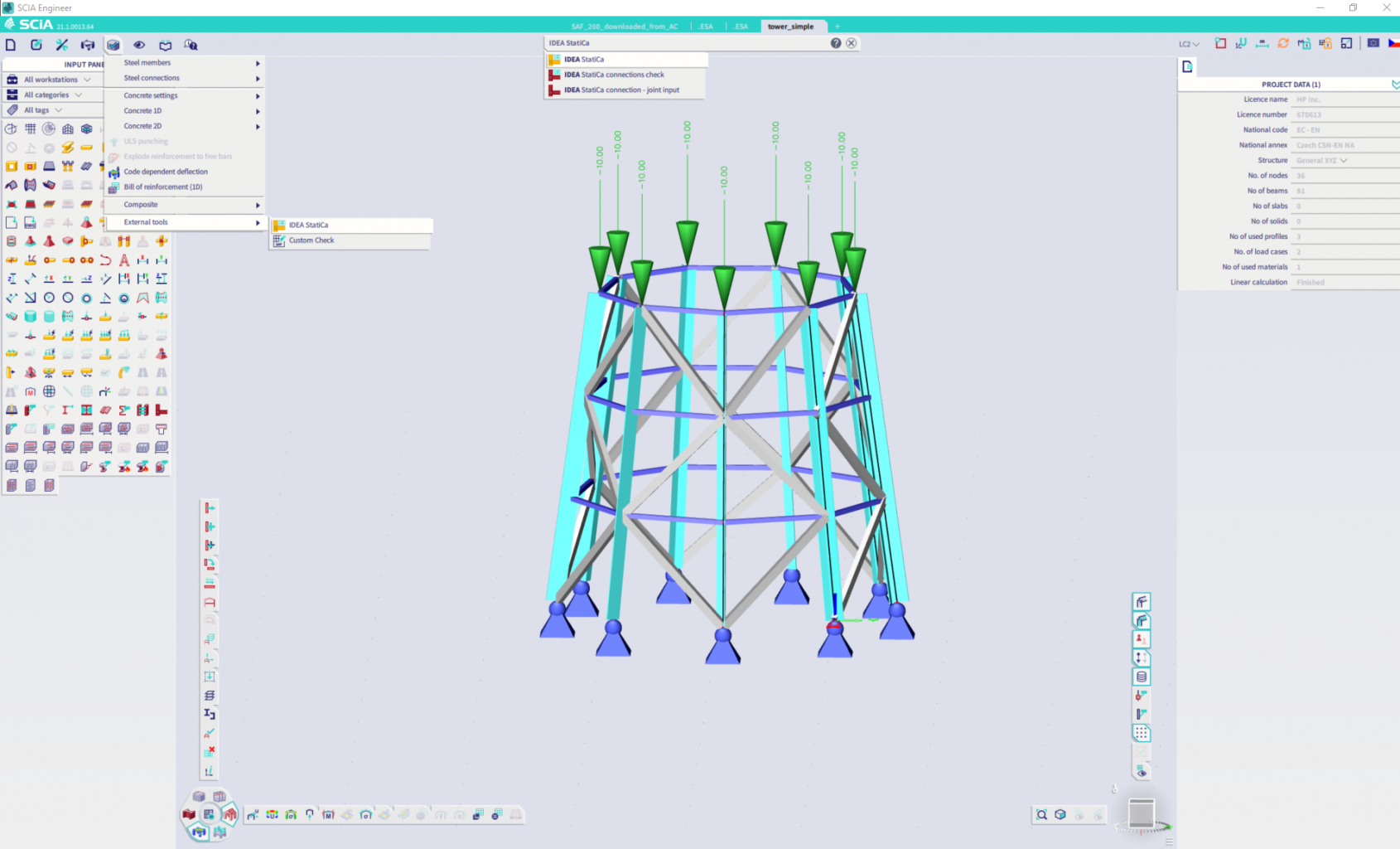
The data exchange is now done in a very simple way using the SAF open-source format for exchange of analytical models. You only need to run the IDEA StatiCa command inside SCIA Engineer 21.1. In a small management application that links the two programs (SCIA Engineer and IDEA StatiCa) you create a project.
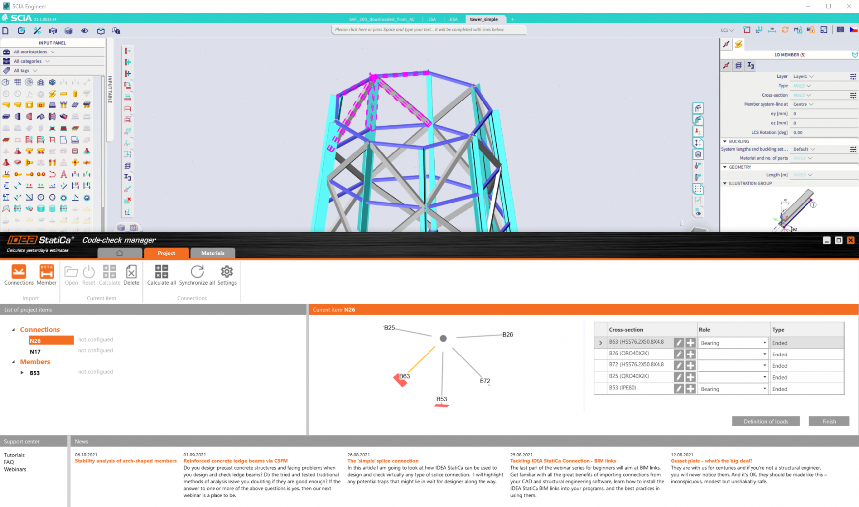
Once the project is created you can start with defining the connections and members for IDEA StatiCa. To do that, you just need to select desired entities in SCIA Engineer and call the “Connections” or “Member” function in the management application. SCIA Engineer and IDEA StatiCa run simultaneously. In the management application, you then define loads you want to be considered in IDEA StatiCa and you are ready to perform the design and code checks.
If you make any changes in the model in SCIA Engineer you simply reset the connection or the member in the management application and run the Synchronize function that updates the data about cross-sections, materials, connected members, loads and geometry. The IDEA StatiCa project is stored next to the .ESA file of your SCIA Engineer project. As long as these files are kept together in one folder, they are connected and cooperating.
SAF 2.0.0 support
SCIA Engineer 21.1 supports all objects defined in the open-source exchange format for analysis models SAF – version 2.0.0.
Newly supported objects are:
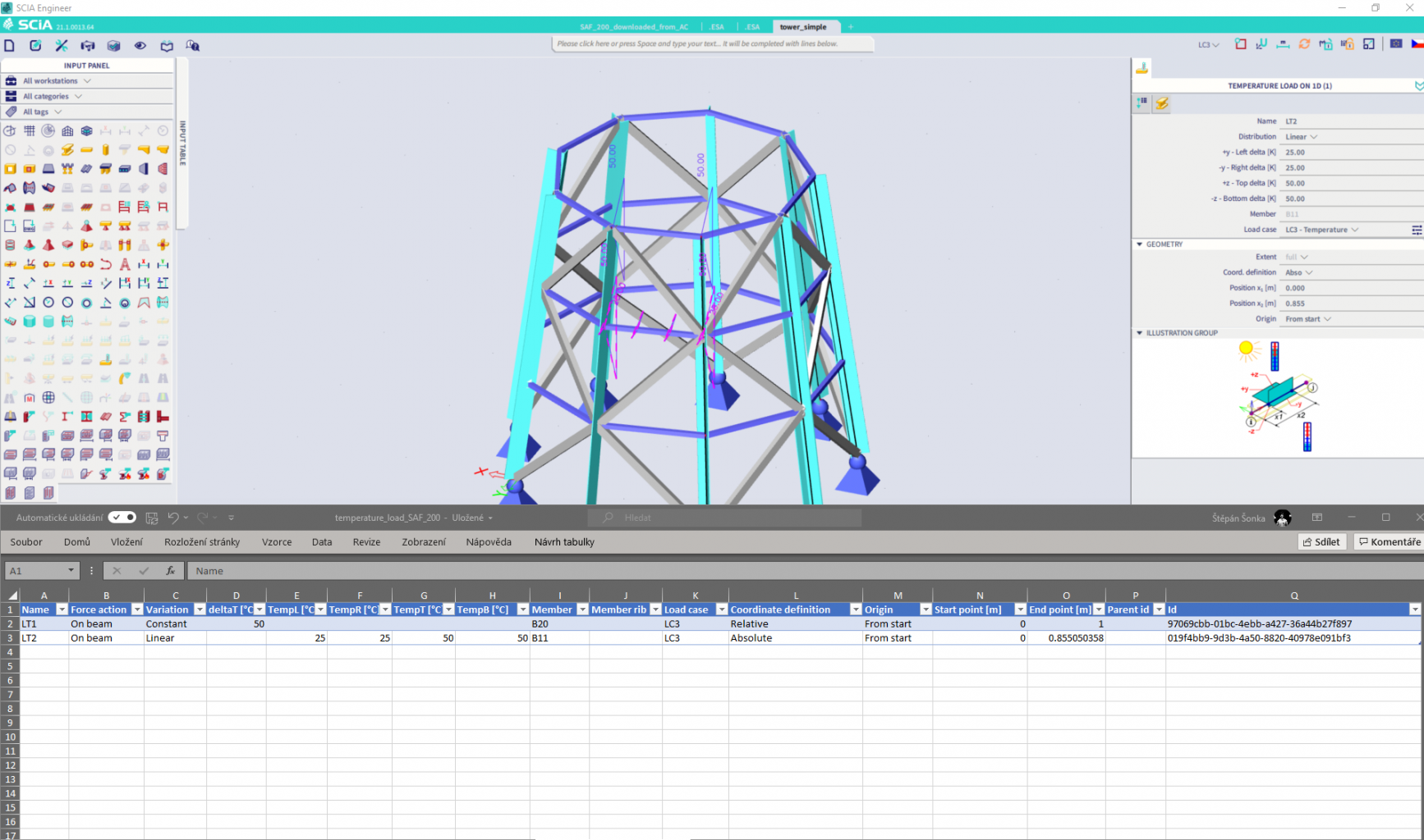
StructuralCurveActionThermal = Temperature load on 1D member
StructuralCurveActionThermal allows users to exchange the thermal loads applied on 1D members. The complete functionality of the object is covered in the SAF specification and therefore there are no data lost compared to SCIA Engineer functionality. Both export and import are supported.
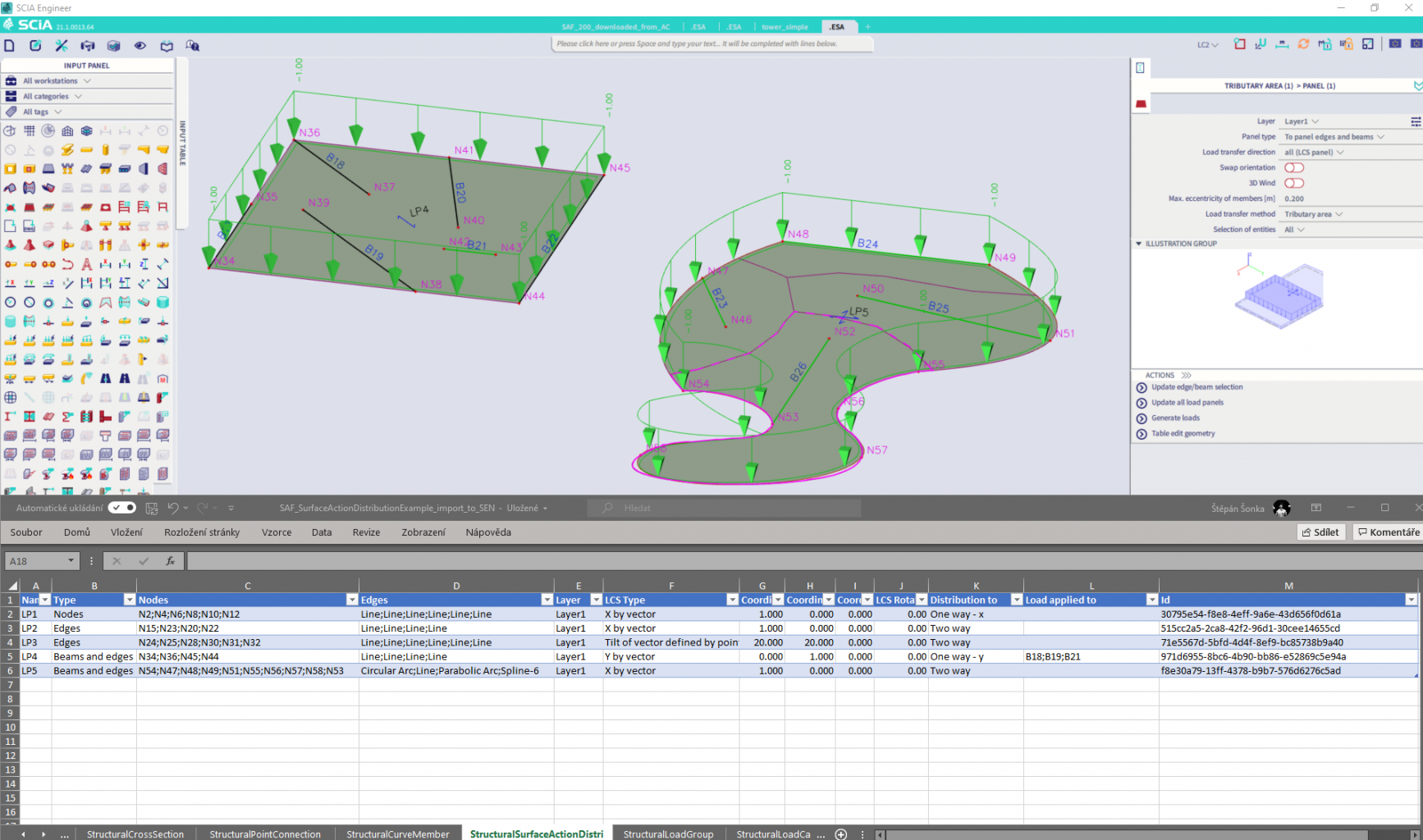
StructuralSurfaceActionDistri = Load panel
Load panels can be both exported and imported from and into the SCIA Engineer with SAF format. Export and import are supported together with a reference from the surface load which can be applied on the load panel. For export and import “Load transfer method” is set to “Tributary area” since this attribute is not defined in SAF. “Load transfer method” can be easily changed in SCIA Engineer or another target application to preferred type of method used.
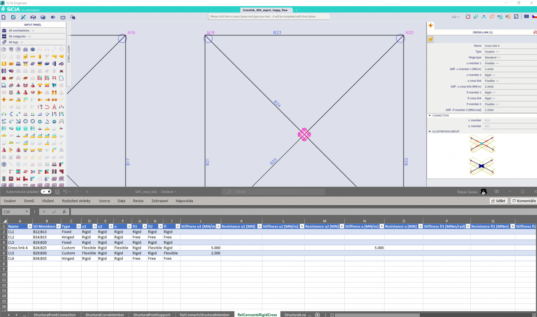
RelConnectsRigidCross = Cross link
Crosslinks can now be exported and imported to SCIA Engineer with SAF exchange services. The supported constraints are predefined as “Fixed”, “Hinged” for crosslinks and “Coupler” with flexible, hinged, or rigid constraints. To ensure that your crosslinks are exported from SCIA Engineer correctly look in the “Info” section after the export to the SAF file is completed. All information about SAF export is presented there.
New objects that are now available for export and import to and from SCIA Engineer via all exchange dialogues using SAF format (BIMcloud, Bimplus, SAF file import and export). For more information about SAF take a look at saf.guide.
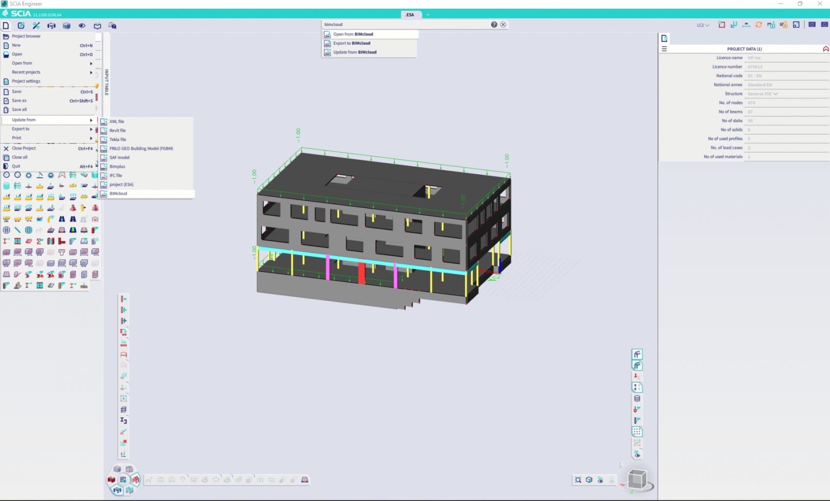
BIMcloud update function
If you model your structure in Archicad, the BIMcloud function allows you to exchange the models with a cloud repository and, from now on, also to update your analysis model with changes done in Archicad. This is important if you have already started your work in SCIA Engineer.
The update is done without losing the references of load objects and supports in your model. You simply run the BIMcloud update, select a new version of the analysis model created by an architect or draftsman and implement the changes into your model in SCIA Engineer. All related objects like loads and supports are kept and you do not need to apply them again. The update works the same way as for SAF model update and Bimplus update commands.