Highlights
- Non-linear material behaviour (ductile and fragile) for 2D members
- Effective modelling of structures that do not transfer tension, e.g., masonry
- Friction supports
- Plastic hinges
- Deep insight in the structural behaviour of structures
This advance module contains friction springs, compression-only surfaces, and plastic behaviour for surface elements.
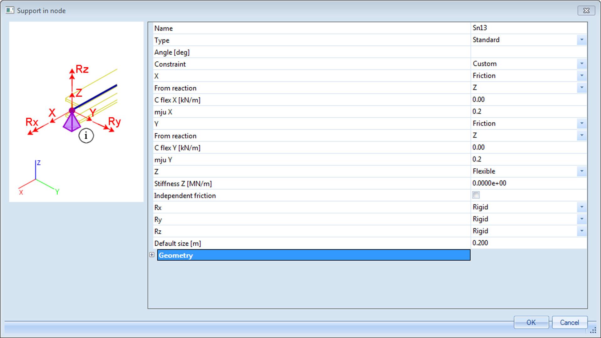
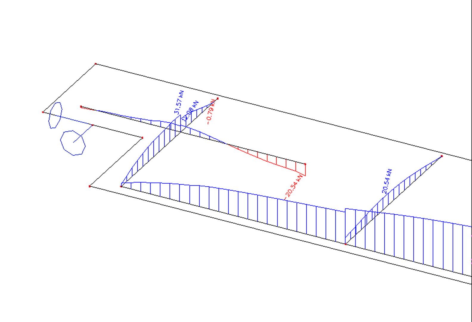
Friction springs in nodal supports
Friction supports can be used to model the fact that a reaction component depends on another component. The horizontal component for example depends on the vertical component. When the friction force is surpassed, the support slips through resulting in large deformations.
Friction supports can be used for several types of structures. Almost every support which isn’t rigidly connected to the surface on which it stands is subjected to friction.
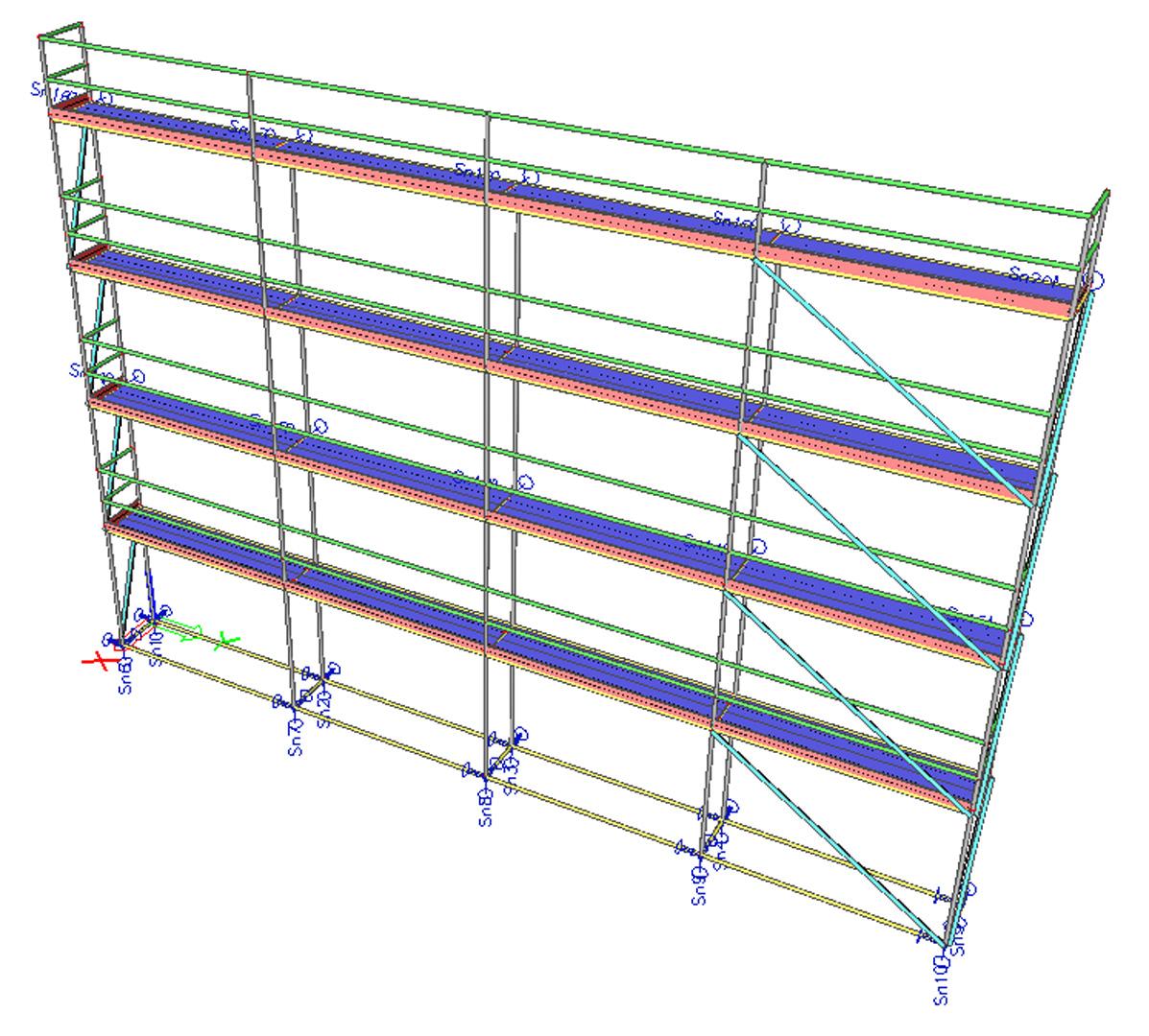
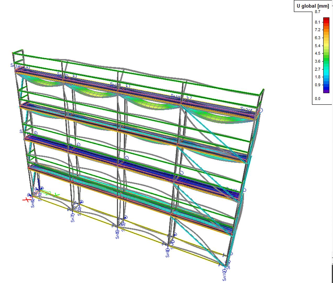
Example of the usage - Scaffolding
Plastic behaviour for surface elements
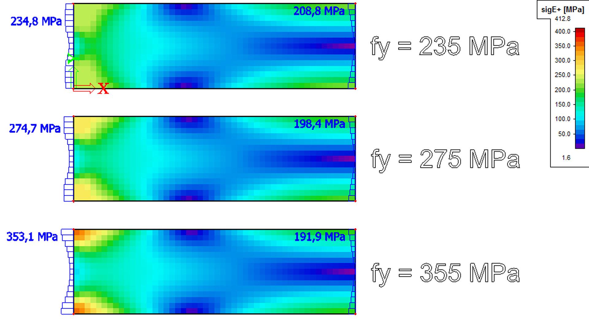
This module allows non-linear material behaviour for 2D members (plates, walls, shells). The plastic zone is based on the isotropic elasto-plastic yield condition (J2 plasticity condition). There is possibility to select from four types of isotropic elasto-plastic behaviour:
- Von Mises
- Tresca
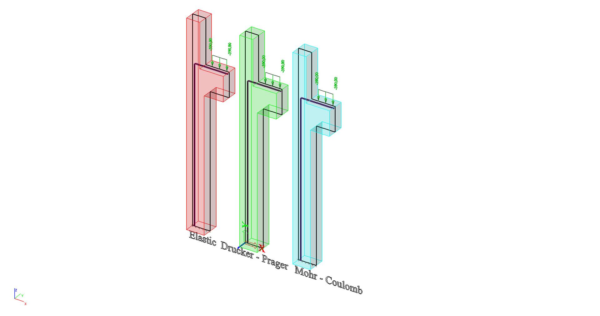
- Drucker – Prager
- Mohr-Coulomb
Von Mieses and Tresca yield condition
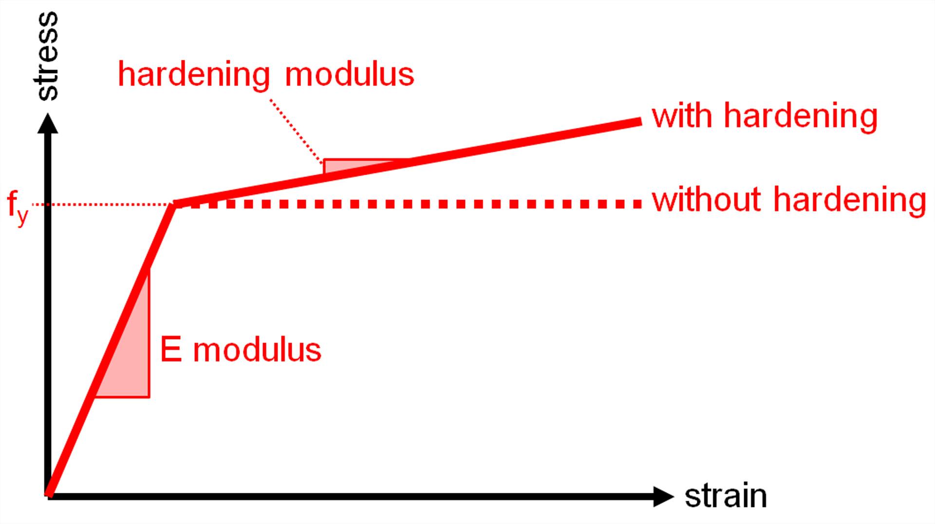
The von Mises yield condition is suitable for ductile materials in general, such as metals (steel, aluminium etc.). It corresponds to a bilinear stress-strain relationship, identical in tension and compression. The plastic branch may have a slope (hardening modulus) or not.
It is a symmetric behaviour, acting in the same way in tension and compression, with or without hardening in the plastic branch.
Tresca yield condition is known also as the maximum shear stress theory. It can be also used for metal materials.
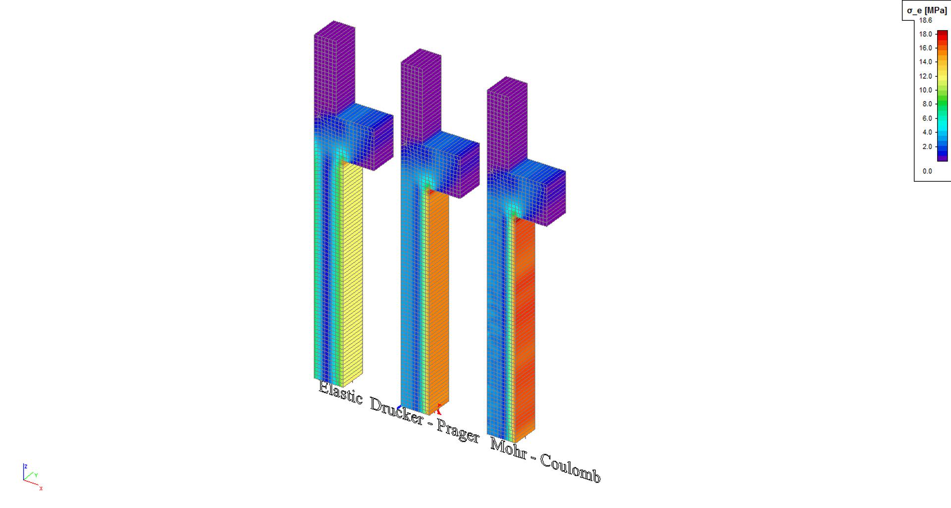
Drucker - Prager and Mohr-Coulomb yield condition
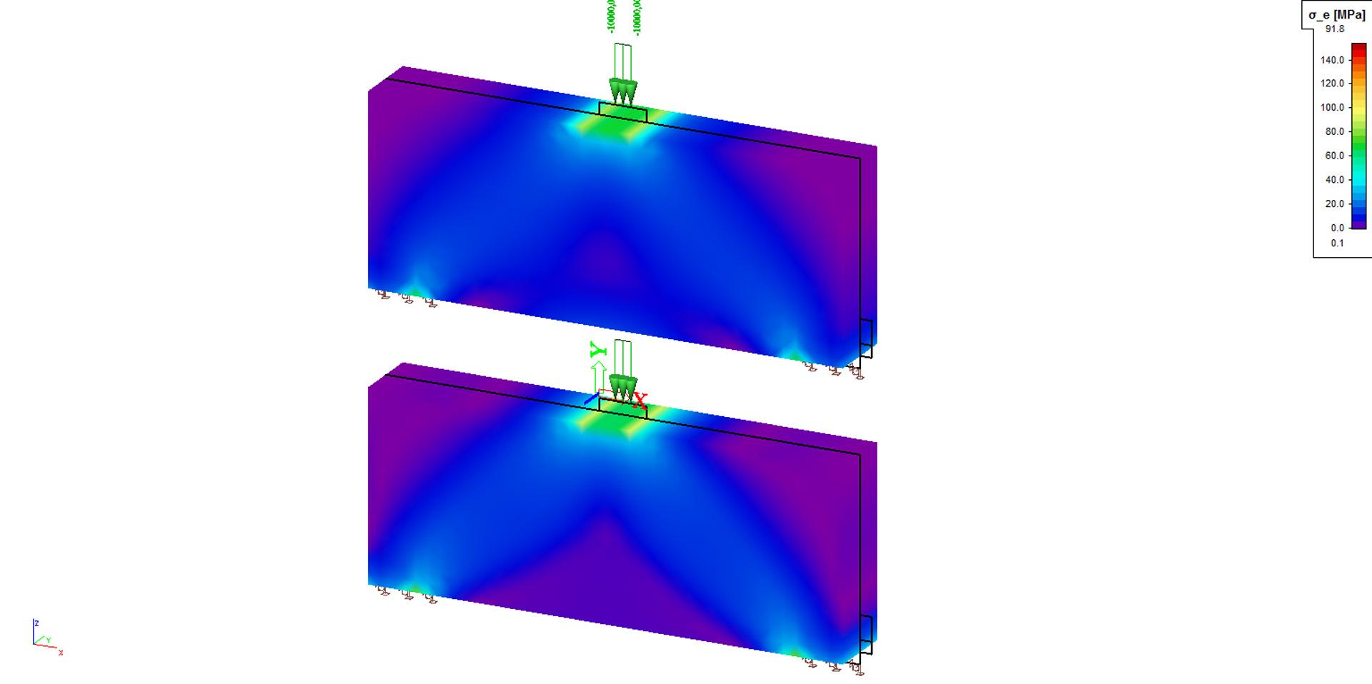
Drucker - Prager yield condition is a frequent used option for concrete where both normal and shear stresses can determine failure. This yield condition can be used for modelling of behaviour of punching, short corbel and for identification of truss analogy to model strut and tie models.
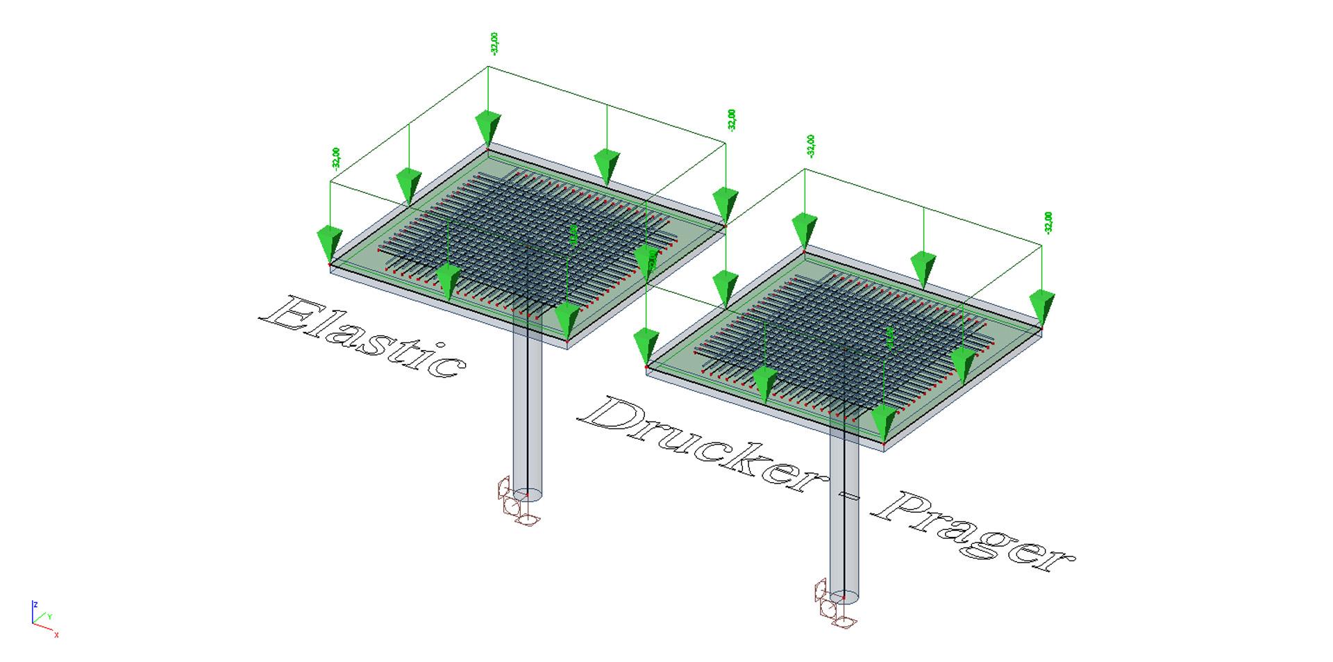

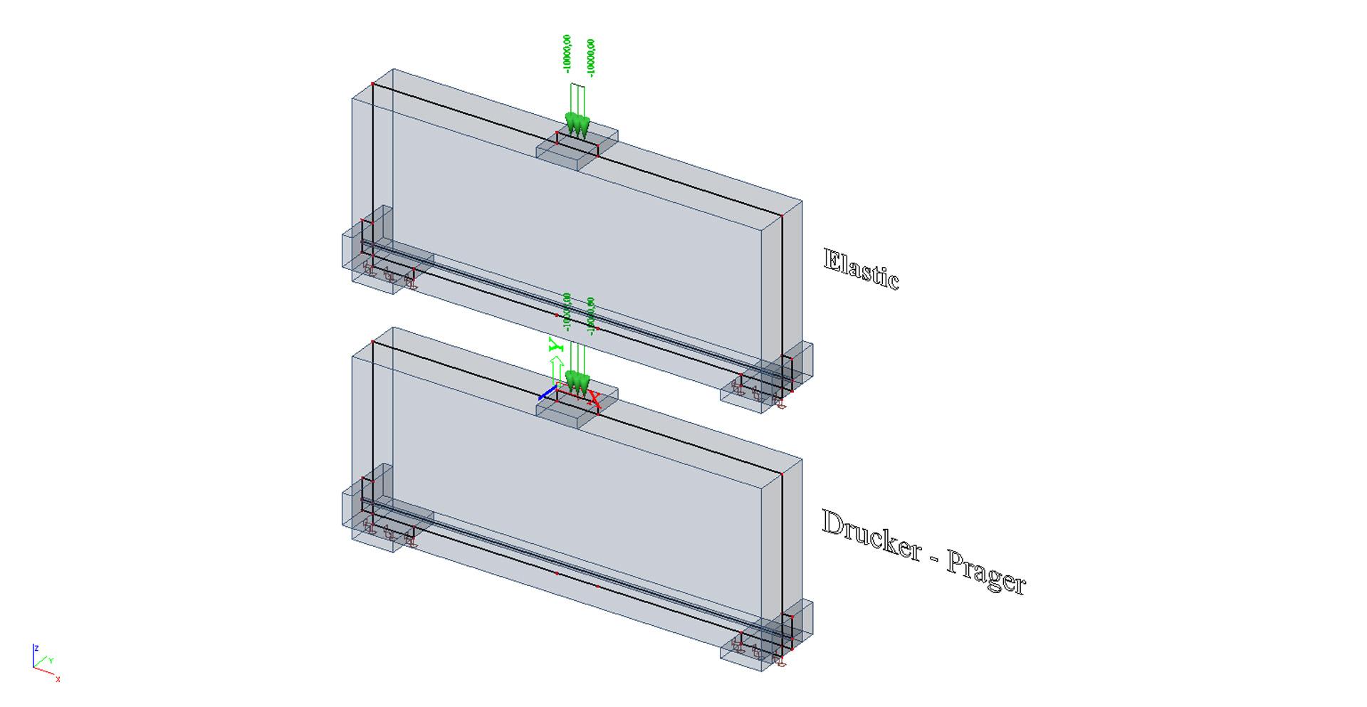
Mohr-Coulomb yield condition is also often used to model concrete, soil or granular materials. This model behaviour law is similar to the Tresca one, with additional provisions for materials with different tensile and compressive yield strengths.
Plastic behaviour with other non-linearities
The plastic behaviour of surface elements may be combined with other types of non-linearity in SCIA Engineer. For instance, surface plastic behaviour, pressure only supports, and large displacement analysis can be used together.
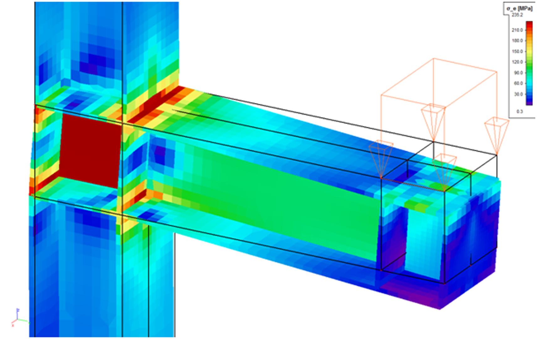
A typical application of general plasticity is a detailed analysis of non-standard steel connections for which simplified methods do not apply. It may however be applied to any structure that can be modelled using 2D members.
Note that this type of plastic behaviour is not supported for 1D members. Any beam or truss member that is present in the model is considered as elastic.
Compression-only surfaces
This functionality allows to analyse 2D members capable of resisting only compression forces. It can be used for example for analysis of masonry walls and arches.
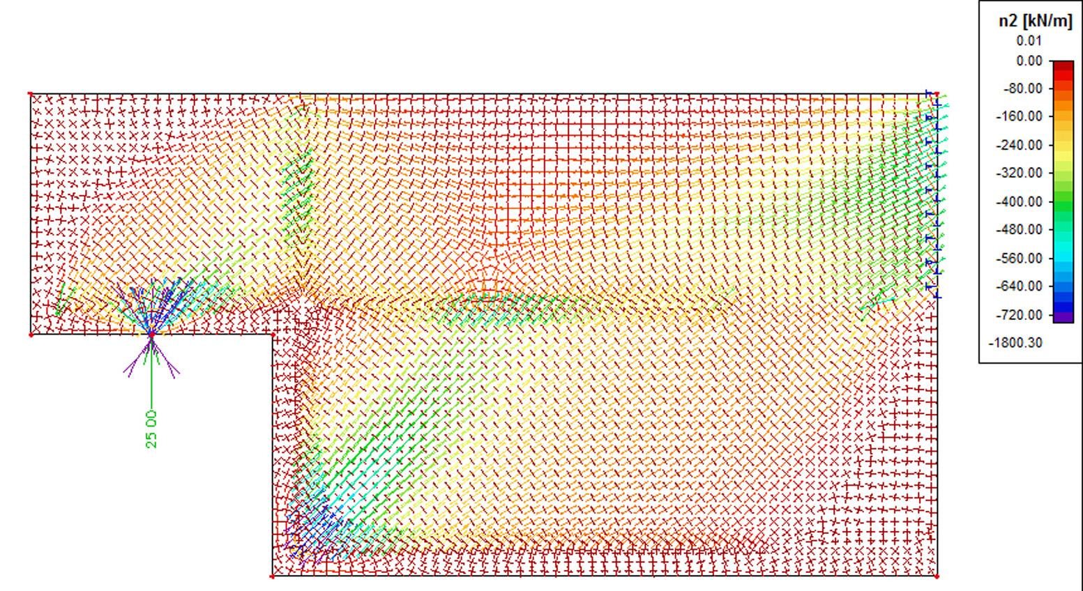
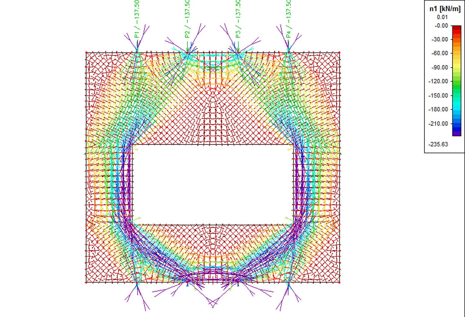
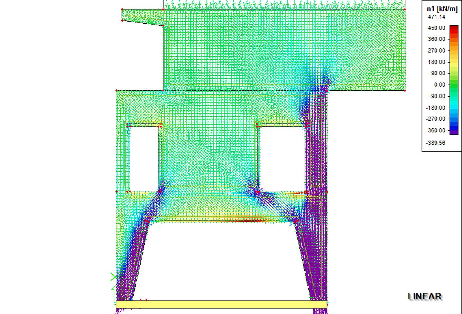
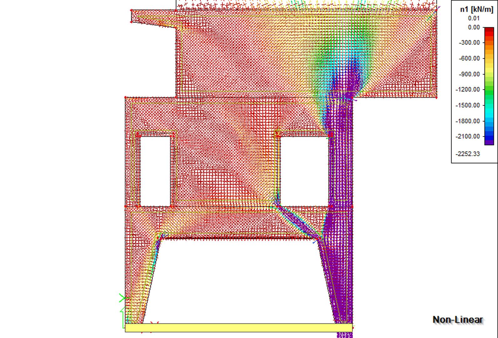
This model gives the user a very good insight into the behaviour of structures such as shear walls or building cores. It is possible to effectively model (reinforced) concrete or masonry structures in a 3D environment. Using a non-linear analysis, the user can reduce all tensile stresses in the concrete or masonry finite elements, which results in a system of compression-only finite elements. The model can display the internal arches/struts above openings and doors. Also, lintels above openings can be easily modelled and considered in the calculation as hinged beams. Reinforcement in the concrete, capable of resisting the tensile forces, is modelled as an internal rib with the area and stiffness of the reinforcement grade. Using this so-called strut and-tie model the user gets a complete tool to design and check the reinforcement in walls.
A non-linear analysis is performed in order to calculate with the pressure-only finite elements. Using a set of iteration steps the stiffness in the direction of the tension stresses is reduced, thus effectively reducing the tensile stresses in the structure. If the geometry of the structure is such that a new state of equilibrium in ultimate limit state is found, i.e., by internal arches or reinforcement, the convergence criterion will be reached.
Using the function for displaying the trajectories of the principal forces or stresses the user is able to adequately review the behaviour of the structure. The internal struts and ties can be clearly seen. The internal forces on the reinforcement can be displayed as axial forces in the structure. Other results like reactions and deformations also help the user to get the proper insight into the behaviour of the structure.
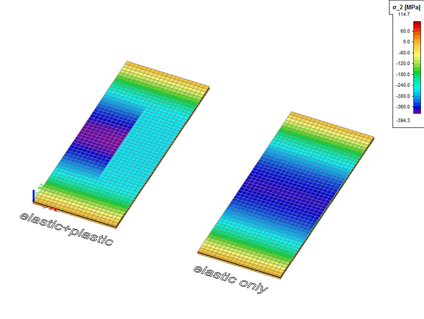
This module helps the engineer in the design and checking of complex 3D-structures with shear walls and building cores. A practical example shows the difference between a linear elastic analysis (according to the service limit state) and a non-linear analysis using pressure only finite elements (according to the ultimate limit state).
The pressure only finite 2D-elements is a must have add-on for the engineer who calculates 3D-structures or 2D-walls in day-to-day practice. This module supplies an adequate insight into the structural behaviour of the structure. Using this module, the user can effectively model masonry or reinforced concrete structures. Practical applications can be masonry walls with openings, concrete walls with openings, special concrete details like tooth-supports of beams.
Plastic Hinges for 1D elements
If a normal linear calculation is performed and limit stress is achieved in any part of the structure, the dimension of critical elements must be increased. If, however, plastic hinges are taken into account, the achievement of limit stress causes that plastic hinges are automatically inserted into appropriate joints and the calculation can continue with another iteration step. The stress is redistributed to other parts of the structure and better utilisation of overall load bearing capacity of the structure is obtained.
Plastic hinges can arise in each FE node of individual 1D members. No selection of 1D members is made by the user for the calculation with plastic hinges. If this type of calculation is selected, all 1D members in the structure can be subject to plastic hinges.
The Solver setup offers the possibility to select the national code (EC, DIN, NEN) used for correction of the limit moments developed in the plastic hinges.
