Highlights
- Design of concrete floors reinforced with steel fibers
- Automatic dosage optimization based on section capacity
- Check of the concrete floors for ULS + SLS
- Design of punching shear when necessary
- Support linear and physical non-linear calculation
Steel fiber reinforced concrete is an alternative to traditional reinforced concrete for certain application areas. Steel fibers are discontinuous, 3-dimensionally orientated, isotropic reinforcement, once they are mixed into the concrete. Steel fibers bridge the crack at very small crack openings, transfer stresses and develop post crack strength in the concrete.
This version of SCIA Engineer contains a smart and sophisticated solution regarding the concrete-steel fiber design. With this solution, the concrete designer can extend his/her possibilities by using SCIA Engineer to design any concrete floor with/without traditional reinforcement and contain steel fibers.
The workflow is quite simple and easy to learn as long as you are familiar with the concrete solution from SCIA Engineer.
Why fiber reinforced concrete?
When steel fibers are added to mortar, Portland cement concrete or refractory concrete, the flexural strength of the composite is increased depending on the proportion of fibers added and the mix design. Steel fiber technology actually transforms a brittle material into a more ductile one. Catastrophic failure of concrete is virtually eliminated because the fibers continue supporting the load after cracking occurs. And while measured rates of improvement vary, steel fiber reinforced concrete exhibits higher post-crack flexural strength, better crack resistance, improved fatigue strength, higher resistance to spalling, and higher first crack strength.
SCIA Engineer version 18 has implemented Dramix® steel fiber reinforcement features with hooked ends, high tensile strength, and ductility. With this solution, the concrete designer can easily select the type of fiber for his/her concrete and do the design based on the German guideline DAfStb Steel Fibre Reinforced Concrete", November 2012.
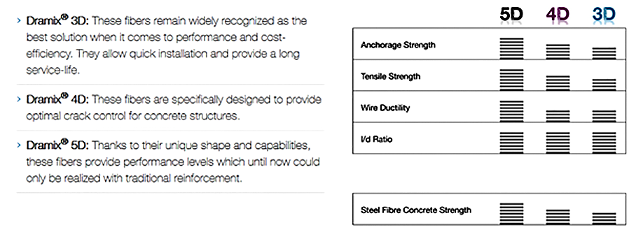
Supported types of steel fiber
In this version of SCIA Engineer, one brand of steel fiber has been implemented (Dramix®). Dramix® fibers are produced by Bekaert company and there are three different types of steel fibers can be used in SCIA Engineer version 18.
The material library for this type of fibers has been constructed in the software and the user can easily pick the necessary fiber type that s/he would like to use to design any floor system.
Moreover, this library is an open source. By means, the user can modify the properties of the fiber to meet the necessary needs in case s/he decided to use a different type of fibers.
Workflow in SCIA Engineer
The workflow for design a concrete floor containing steel fiber is very simple. If you are familiar with the concrete design solution from SCIA Engineer, then you do not need to worry about that. Basically, the property menu for SFCR is quite similar to the one from the traditional concrete design.
Step by step workflow
1. Starting a new project and selecting the necessary material.
As usual, you need to select the necessary material from the project data when you start a new project in SCIA Engineer. However, for designing a concrete floor containing fibers you need to activate the traditional concrete material and steel fiber concrete material as well. This is because of several parts of the design depends on the general requirement of the EN 1992-1-1 Code and the part which related to the fiber design is depends on the German guideline.
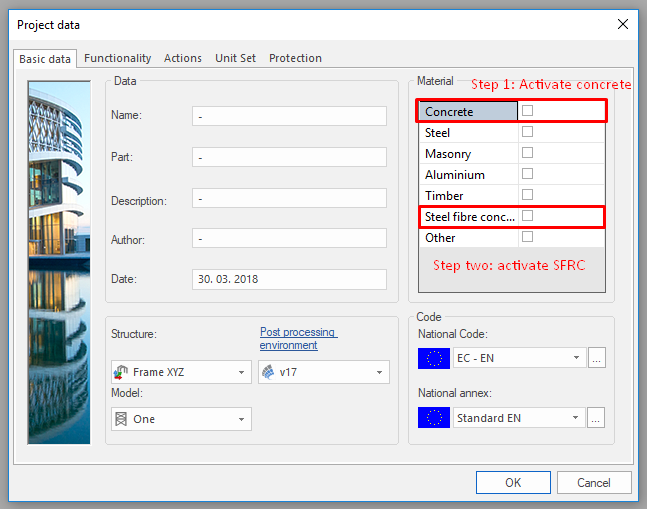
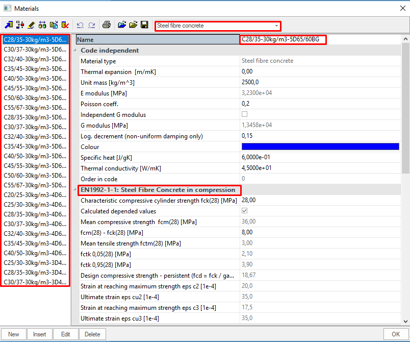
After the activation, the user can see that SCIA Engineer has constructed the necessary library for SFRC. In this library, all the material properties related the type and content of the steel fiber are there which should be used during the design.
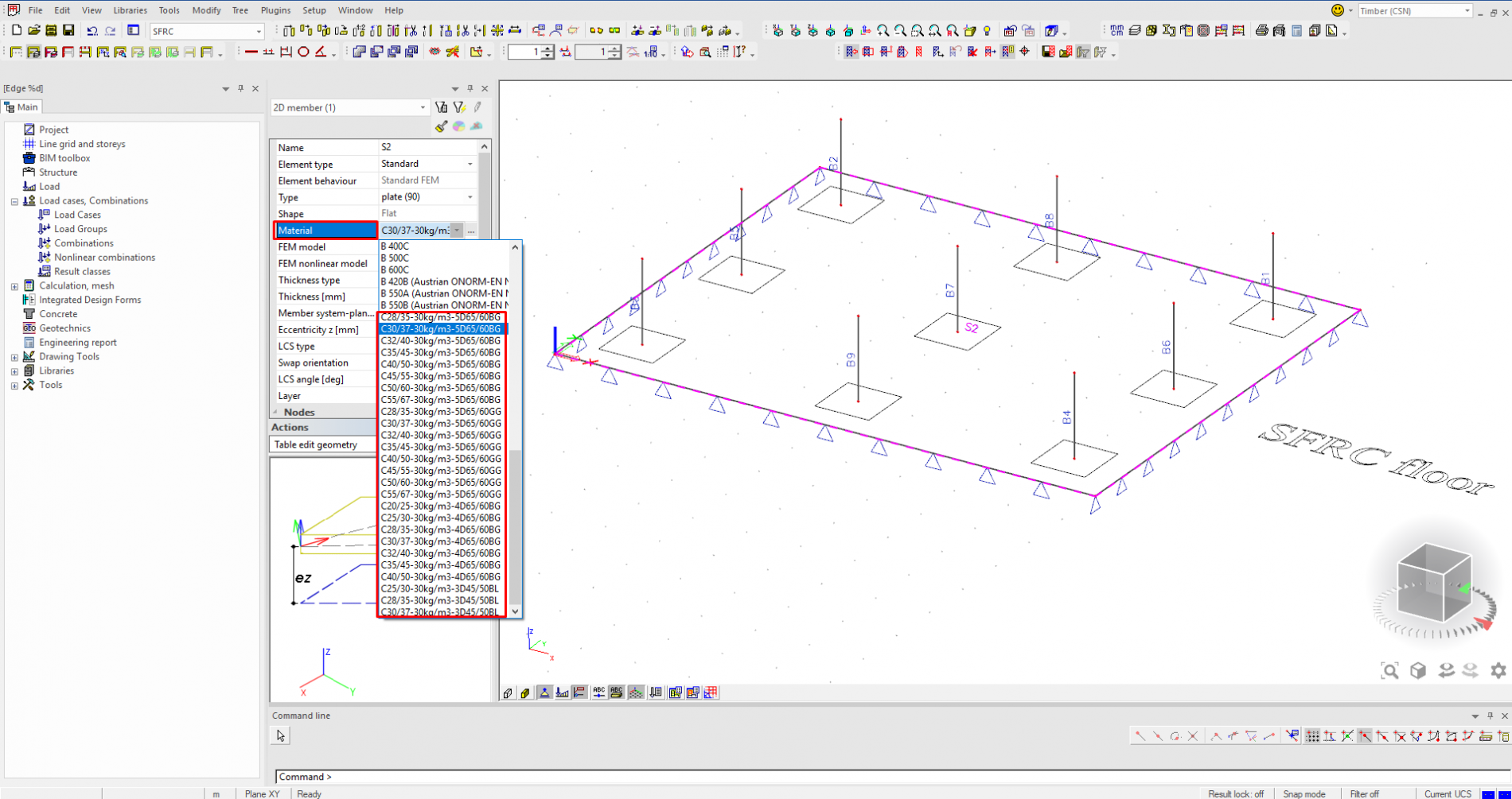
2. Model your structure and assign the SFRC material to your floor.
The good thing about this solution is that the user can do the modeling of a normal structure as he used to do that with SCIA Engineer. After, the user can assign the necessary steel fiber material to any 2D element in his structure. This is also can be done from the beginning by selecting the material as SFRC before making the 2D element.
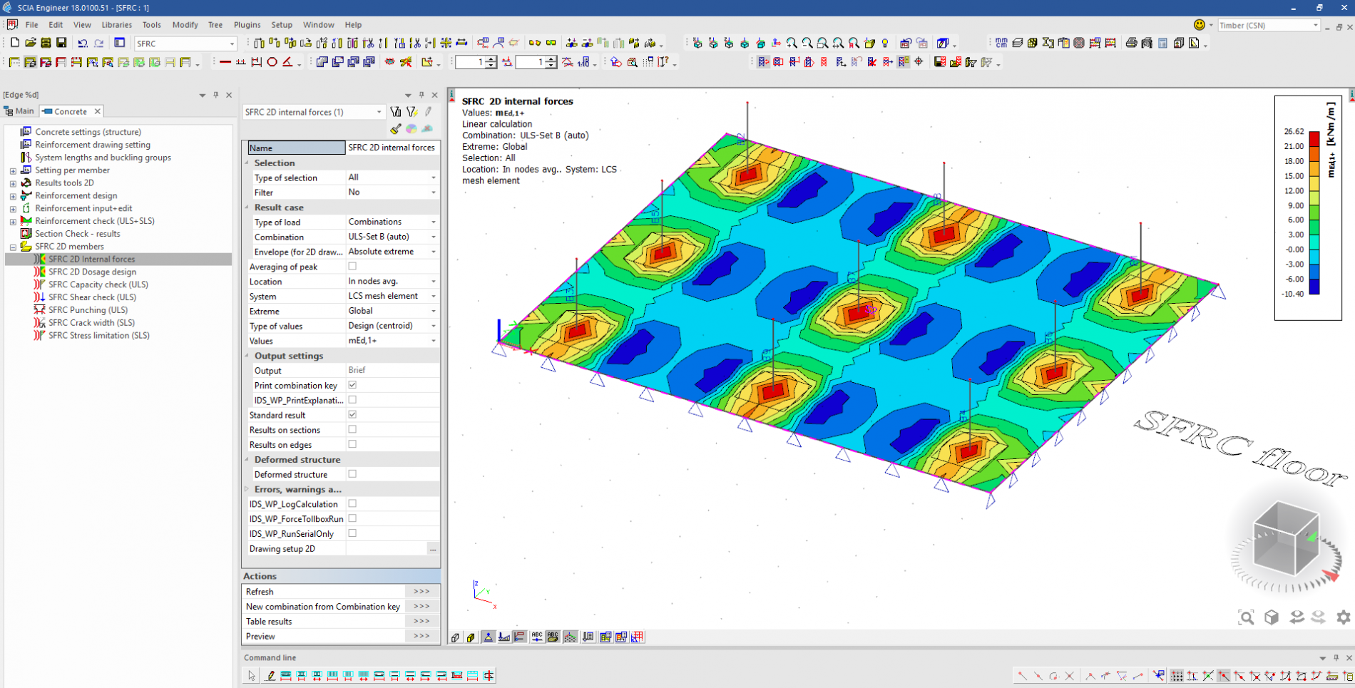
3. Run the calculation
In this solution, SCIA Engineer supports the linear and non-linear calculation.
With the linear calculation, the user can see the internal forces for the 2D elements in a similar way like for traditional concrete floors. All the internal forces for the design will be calculated in the direction of the traditional reinforcement.
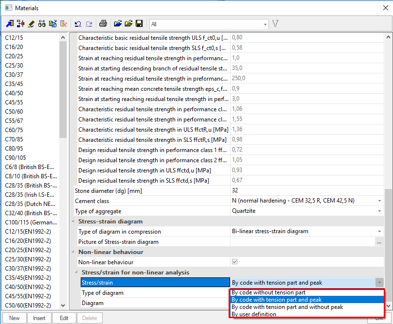
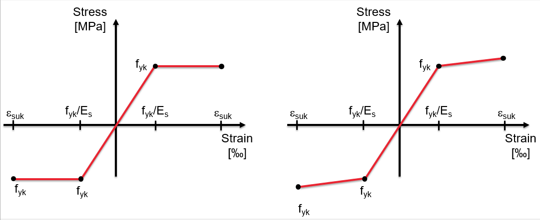
From the check side, the user can use two different stress-strain diagram as show in the image below.
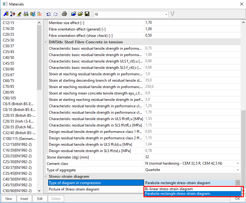
For the non-linear calculation, the user can use the brand new physical nonlinearity for the analysis of concrete (with/without traditional reinforcement and with/without steel fiber). With this method of analysis, the user can simulate the real material behavior during the analysis. In addition, the user can define his/her stress-strain diagram or use the existing ones from the German guideline regarding the SFRC.
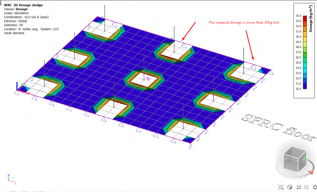
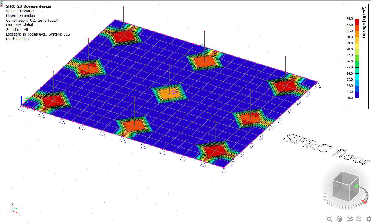
4. Steel fiber dosage calculation.
This version of SCIA Engineer supports an automatic calculation of the steel fiber dosage. This calculation can be done linearly or nonlinearly. During this calculation, SCIA Engineer will assume maximum dosage amount per mesh. This amount will be reduced by iteration calculation to meet the requirement from the ULS capacity check.
The dosage amount of the steel fiber is limited between 20-35 Kg/m^3. If the dosage design reaches the upper limit (35 Kg/m^3), then the user can see blank spots presented graphically. This limit has been set like that to remind the user about the cost-effectiveness of the design.
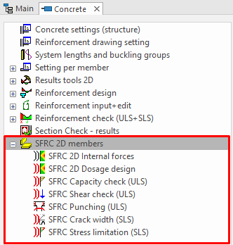
5. Checking of SFRC floors
Besides the calculation of steel fiber dosage, this version of SCIA Engineer, supports the ULS and SLS checks. these checks can be used to give the concrete design the comfortability to design his/her concrete floors.
As a part of this solution, the concrete designer can see the capacity check (ULS), shear checks (ULS), Punching design (ULS), crack width calculation (SLS), and the stress limitation (SLS). With all these checks, the user can define the Kgs of fibers or use the already defined one from the library or even better, to use the value from the automatic design to check the 2D elements.
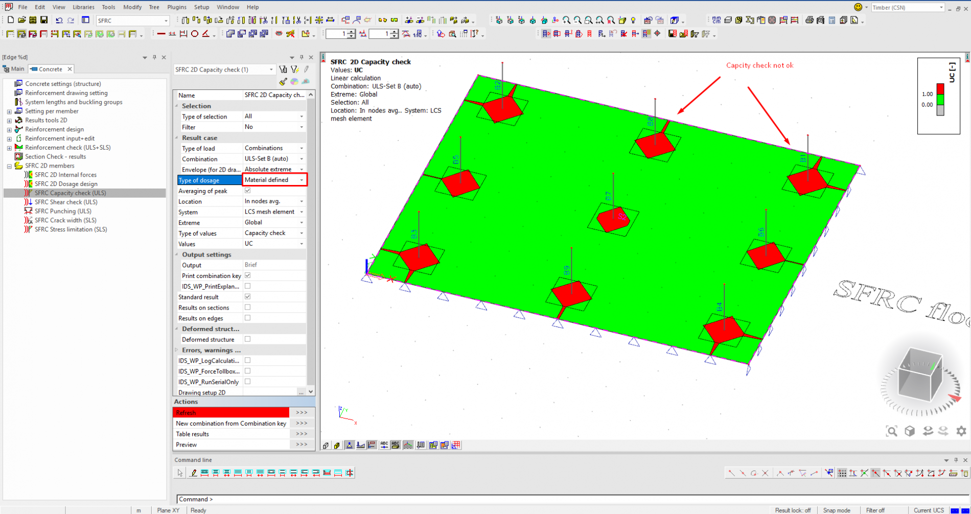
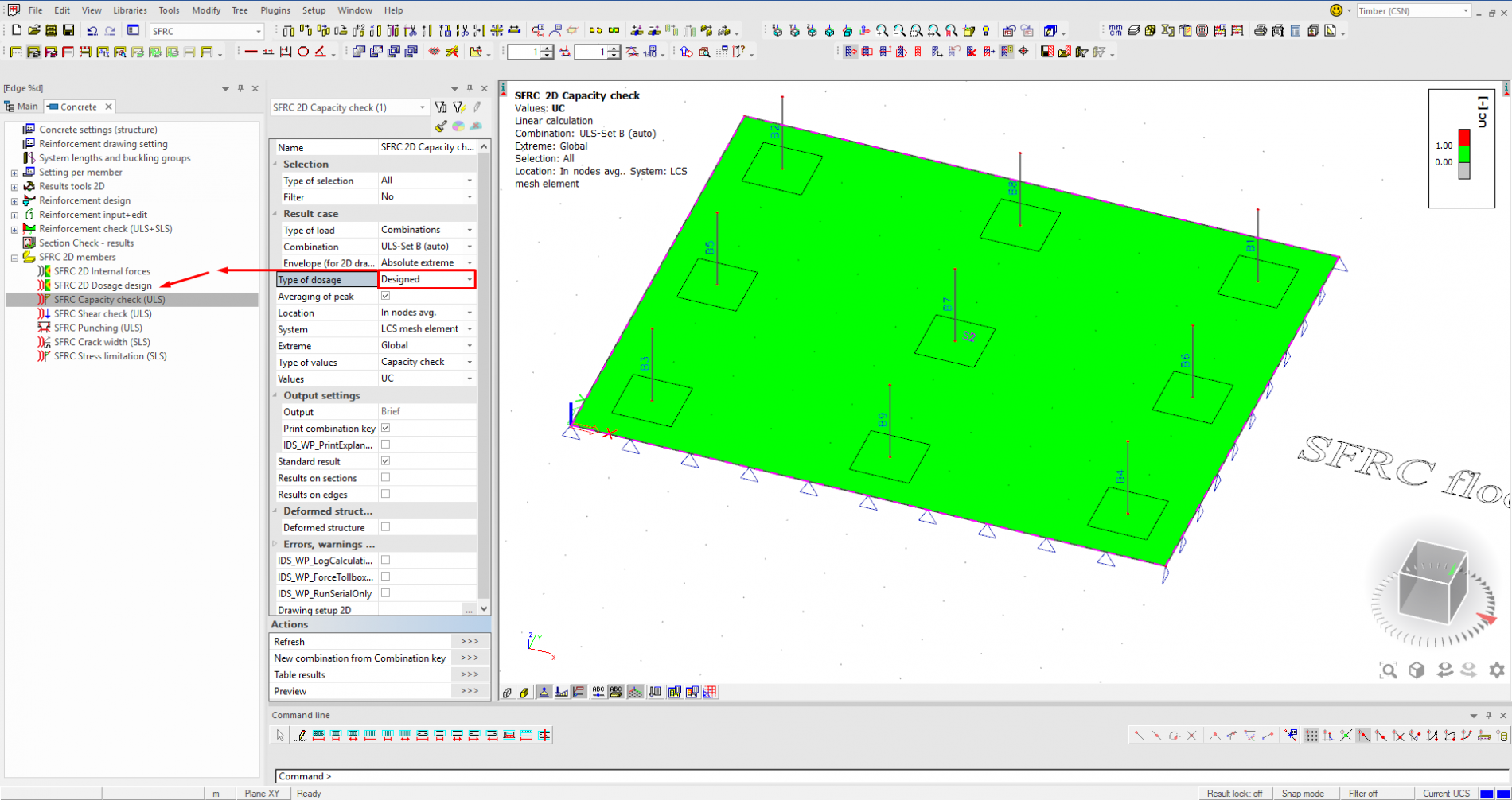
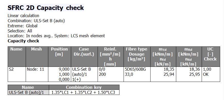
A. Capacity check (ULS)
With this capacity check, the concrete designer can check if the capacity of the concrete floor which contains fiber is safe or not. This check is including the influence of the steel fiber on the resistance of the 2D elements.
B. Shear check (ULS)
This check is designed to give the user a quick estimation about the resistance of the concrete floor which is containing fiber.
The influence of steel fiber is calculated based on this formula from the German guideline
Calculation of vfRd,cf
vfRd,c = min(vRd,c, + vRd,cf; 1.4 ∙ vRd,c)
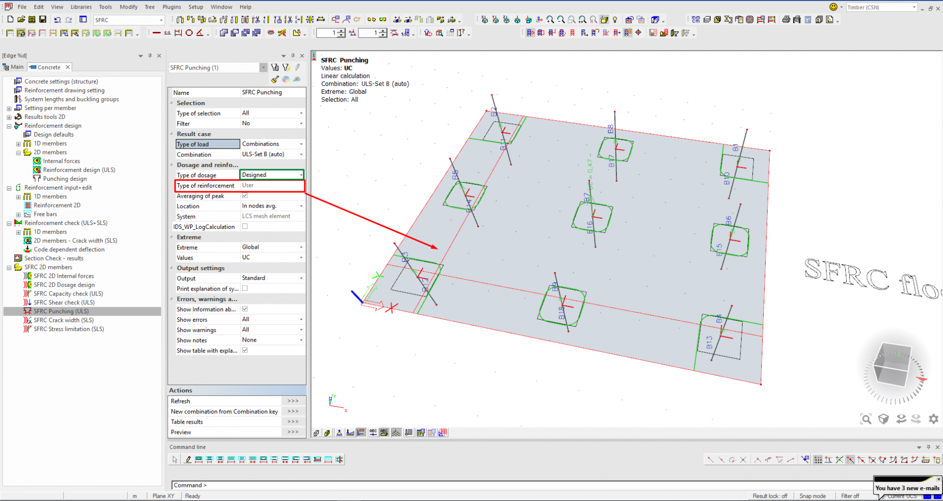
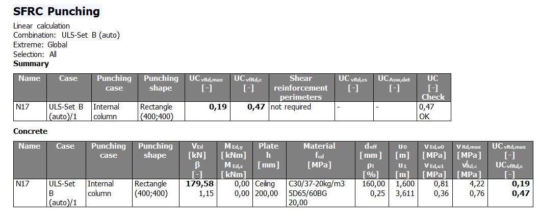
C. Punching design (ULS)
The punching solution for SFRC is quite similar to the solution from the traditional concrete. The only difference is the influence of the steel fiber on the calculation of the 2D element which is already described in the previous step. So, if the resistance of the floor is not enough SCIA Engineer will calculate the necessary punching shear reinforcement in a radial way around the support. For punching design and check, the user can use a plain concrete reinforced only with steel fiber or even s/he can combine the traditional reinforcement with the steel fiber and in this case, the practical reinforcement as real bars only supported.
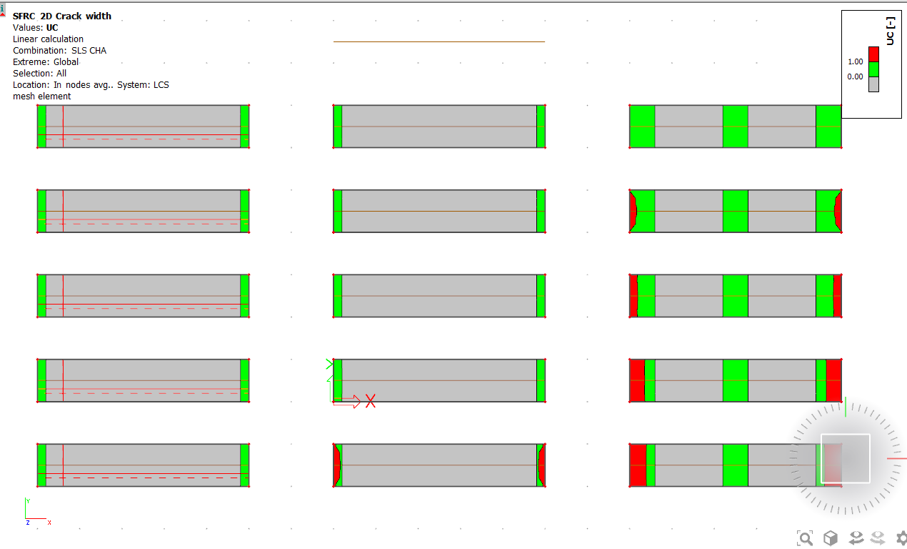
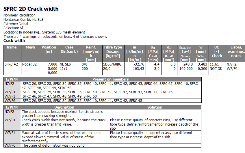
D. Crack width check (SLS)
This check is designed to let the concrete designer check the size and the location of the cracks inside the floor slab containing steel fiber. The method of the calculation is quite similar to traditional concrete. Some modification is there according to the German guideline to respect the influence of the existence of the steel fiber inside the concrete.
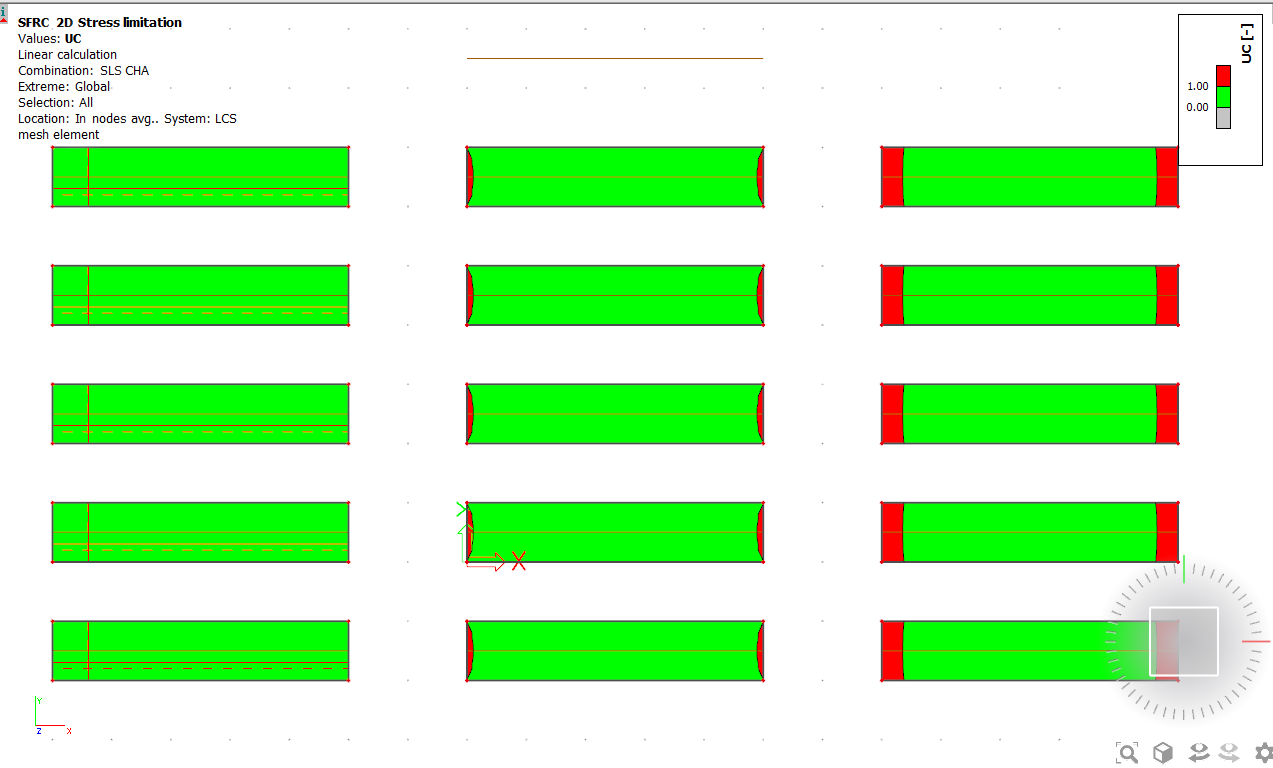
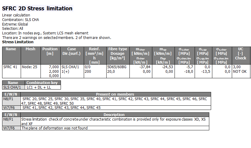
E. Stress limitation check (SLS)
Besides the crack width calculation, the user can use this check to keep the stresses inside the fiber concrete and reinforcement within the limits. The steel fiber has no direct influence on the calculation of the stress inside the fiber reinforced concrete. All the calculation in this check is based on the calculation of the standard concrete.
Physical and geometrical non-linear calculation for reinforced concrete floors with or without steel fibers
Physical non-linear calculation represents very powerful tools for analyzing any kind of structure in civil engineering build-up not only from steel fiber reinforced concrete but also from the other materials.
Generally, the user can obtain different results compared with the linear calculation, especially in case of hyper-static structures. In case of linear analysis, just E-modulus of material is taken into account for the preparation of stiffness matrix. There is no stress distribution based on increasing of strain in the structure.
Besides that, the non-linear calculation provides stress re-distribution and increasing of bearing capacity after reaching of the ultimate strain until the collapse mechanism based on different values of stress and strain depending on the pre-defined non-linear stress-strain relationship in the material diagram.
Especially for steel fiber reinforced concrete, this analysis can provide a real behavior of the structure with different results compared with the linear analysis.
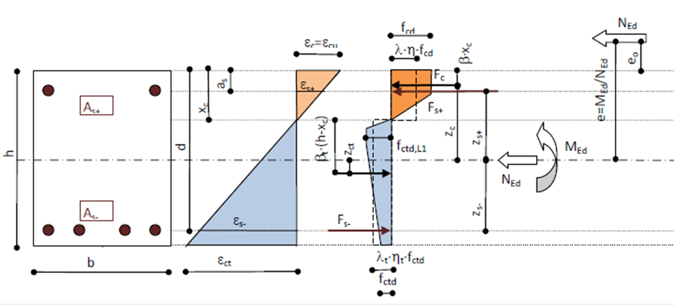
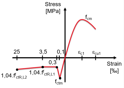
A typical shape of the stress-strain diagram is visible in the following figure, where parabolic behavior is used in compression as in standard concrete. The tensile behavior represents the narrow peak expressed as mean tensile strength. From the point of strain, this peak works very well as a crack localization. After the crack formation, the toughness of SFRC allows keeping a certain level of tensile stress with increasing of strain up to failure which is fixed as 25‰.
Generally, there are two types of tensile branch based on selected fiber type with softening or hardening post-cracking behavior (5D and 4D with ascending branch and 3D with descending branch in tension). The diagram for non-linear analysis are prepared based on user-defined dosage and points are generated according to requirements in DAfStb Guideline "Steel fiber reinforced concrete"
All the results from this method have been checked based on hand calculation and result from experiments on real-life projects. The accuracy of the results from SCIA Engineer solution and the hand calculation was quite acceptable.
First introduced in version 18.0

Want to try SCIA Engineer yourself?
Explore how our software and services can help you optimise your work and boost your productivity. Try it for yourself with a free 30-day software trial.
Download a free 30-days full trial