Create high resolution pictures
There are different ways to create an image from your SCIA Engineer model (with or without results). The best known method is making a screenshot by means of the Print Screen button or a special tool for screen captures.
But suppose that you want to use this picture for an important document, presentation, website or user contest participation... In that case, it might be required to save the picture to a format in high resolution. Here you will find some tips on how to create such nice and high resolution images from your SCIA Engineer models.
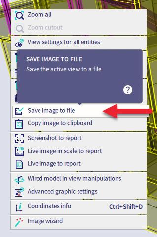
In SCIA Engineer use the right-click pop-up menu and select Save image to file.
Next, you get the choice between different types of graphical formats:
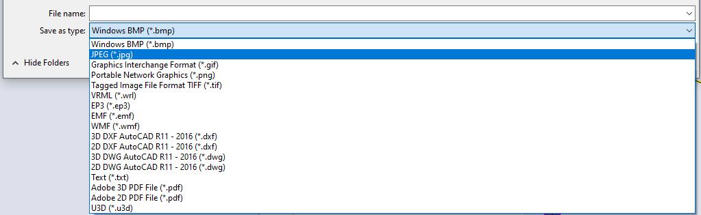
Let’s take the most frequently used graphical format: JPEG (*.jpg). After inserting a file name for your image, the following dialog pops up:
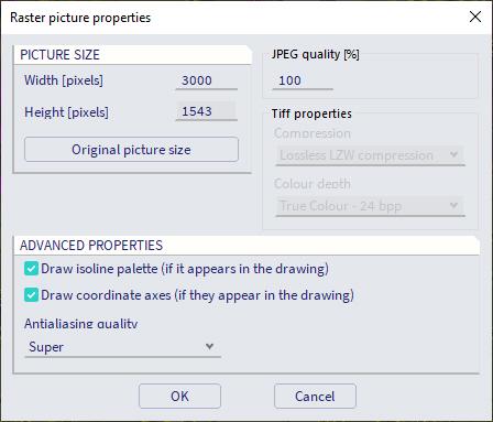
It’s very important to choose a big picture size here. You are able to fill in the width, where a recommended value is 3000 pixels for high resolution. The height is automatically adapted. It’s possible to enter a value between 10 and 100000 pixels for the width. But the larger the size, the longer it will take to save the image.
You can also adapt the JPEG quality. This can be put to 100% for the best quality. Furthermore, it’s possible to (de)activate the isoline palette and the coordinate axes, if they appear in the drawing.
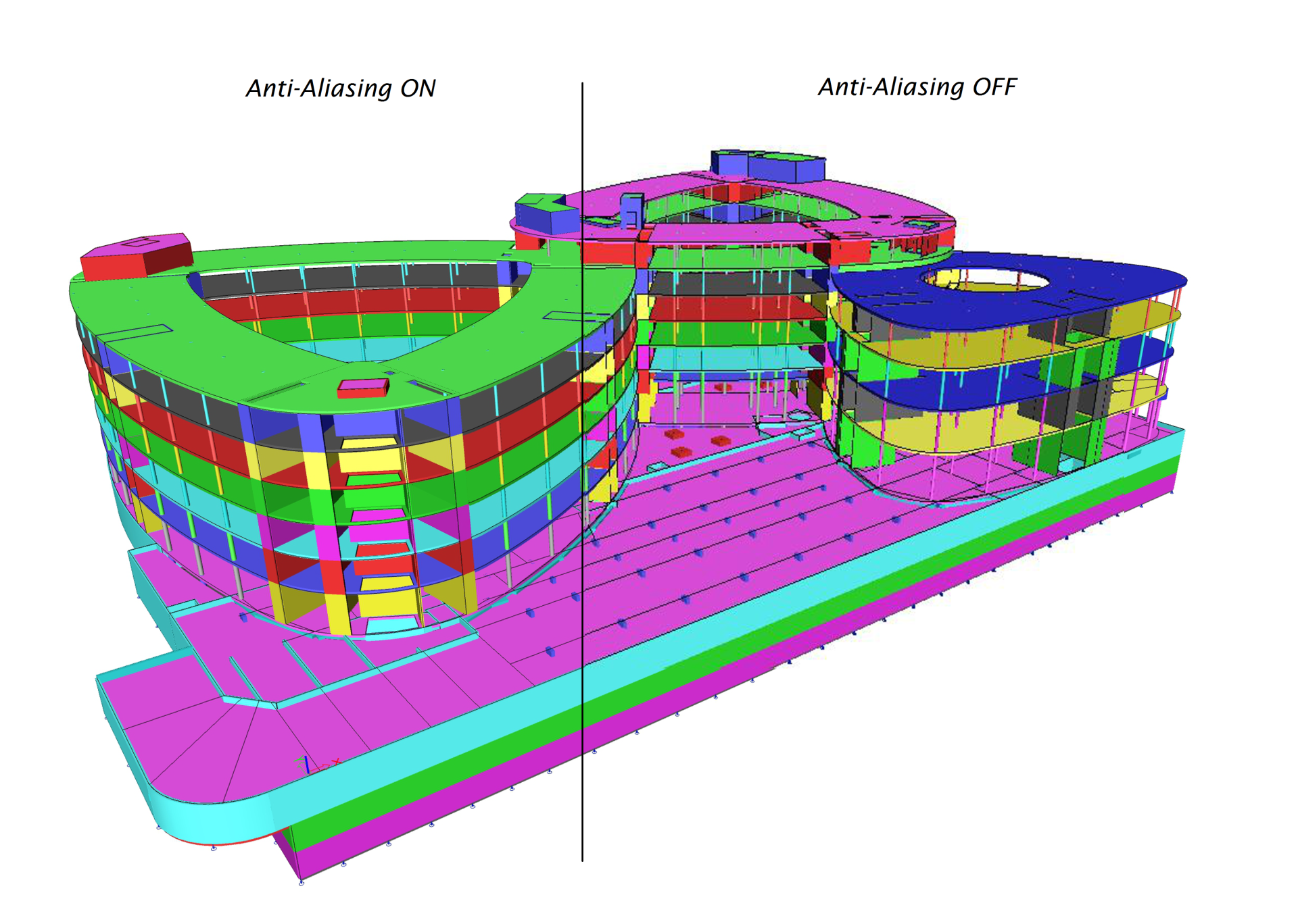
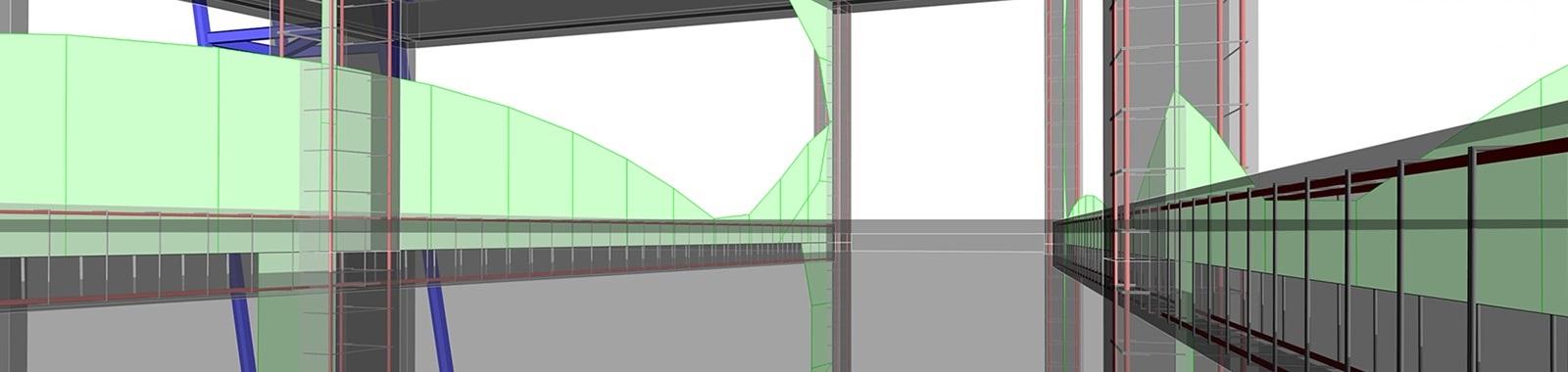
Another important feature is the anti-aliasing option. We always recommend to put this to "super", as this will give you much smoother images. You can notice the difference in the example below:
Other settings to consider that will improve your image exports
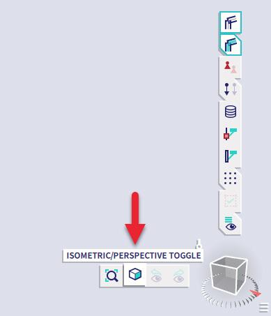
Perspective mode: the best view for pictures can be obtained with the perspective view.
Rendering: for viewing the model and making screenshots of it, it’s the best to render the structure. Not only the model, but also loads, reinforcement and supports can be rendered. Do notice that rendering demands more power from the graphical card and your PC's memory.
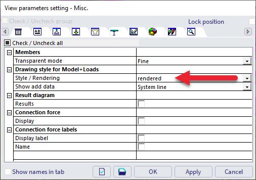
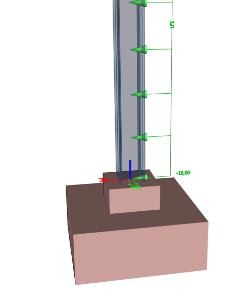
Transparant mode: in some cases, it is practical to choose the transparent mode instead of the fully rendered mode. Take for example for concrete, the reinforcement is only visible in case we select the wired or transparent mode.
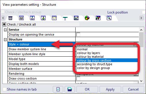
Style + Colour: in the view parameters setting, you can find most settings for the display of the model. One of the options is the colour of the model.
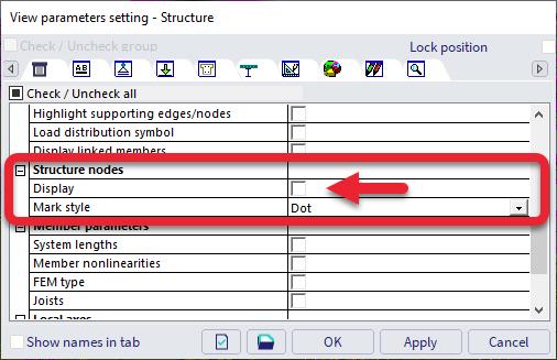
Display structure nodes: structure nodes are in most cases indicated as red dots. For creating a nicer and cleaner picture, it’s recommended to switch this nodes option off.
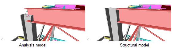
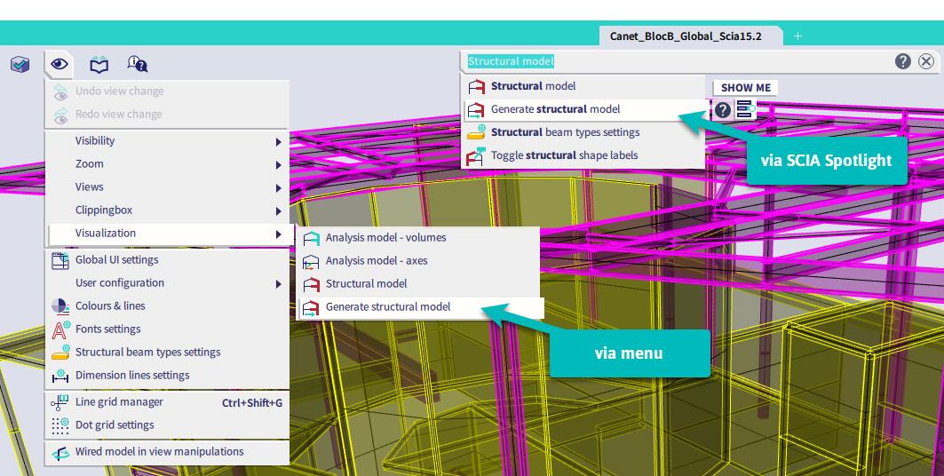
Structural model: it’s important that system lines are connected to each other. On the other hand, for the graphical (CAD) model, it’s important that the volumes of the rendered structures are correctly connected. For this, you can activate the structural model in the project data dialogue.