Highlights
- Successive assembling or casting of structural elements
- Progressive construction of cross-sections
- Gradual application of loads and prestressing
- Changes of boundary conditions
- Modification of Material Young modulus through stages
- Removal of temporary structural elements
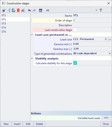
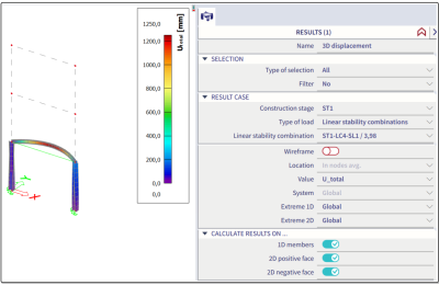
- Stability (Buckling) Analysis on every stage
- Design and Checks on every stage
Since civil structures are frequently designed and constructed with miscellaneous materials (e.g. steel, prefab and in-situ cast concrete), the static system of the structure changes during its erection. This module enables you to calculate structures that consist of 1D and 2D elements in different phases. The stress history is calculated by taking into account added or removed supports, members, hinges, load cases, changing cross section properties etc.

The evolution of the static system of the structure in each stage is taken into account through the
- Adding or removing 1D and 2D structural members as well as tendons,
- Adding or removing all types of supports,
- Adding or removing all types of hinges,
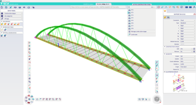
Moreover, it is possible to account for:
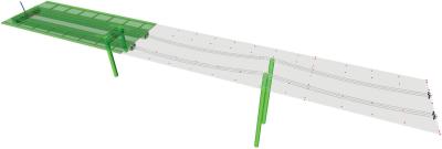
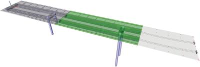
- Progressive construction of members (e.g. composite bridge deck):
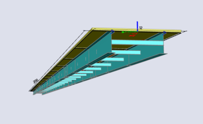
-
Progressive construction (adding, removing, re-adding) of cross-sections:,
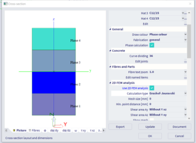
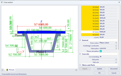
-
Gradual application of loads and prestressing (when combined with “Prestressing modelling and analysis” module sens.21).
-
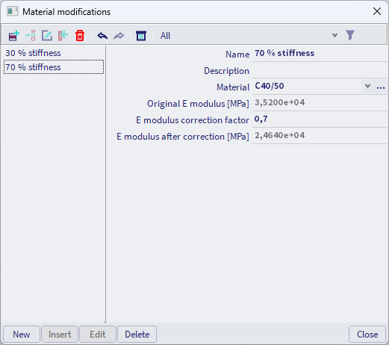
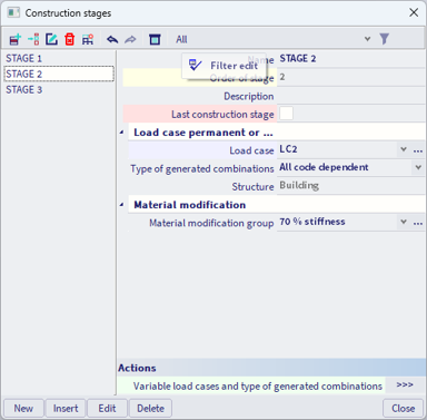
Modification of material E modulus over stages
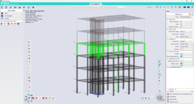
- Design and Checks on all stages
-
Stability (Buckling) analysis on all stages

Want to try SCIA Engineer yourself?
Explore how our software and services can help you optimise your work and boost your productivity. Try it for yourself with a free 30-day software trial.
Download a free 30-days full trial