Highlights
- Full automation of construction stages and detailing at the level of loads, analysis and design.
- Ultimate and serviceability design in accordance with EN 1994-1-1 or AISC 360.
- Checks of openings in steel webs, fire resistance checks and floor vibrations.
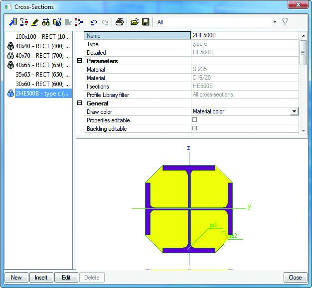
- Support of 9 cross-sections in this module
- The analysis can be carried out for a linear or a non-linear combination.
- Possibility to create user-defined concrete grades
- This module takes into account the time dependent effects by computing the flexural stiffness
- ULS check includes pure axial, combined axial plus uniaxial bending, combined axial plus biaxial bending, longitudinal shear check, transverse shear check
- Possibility to have a detailed output with all intermediate calculations and used clauses
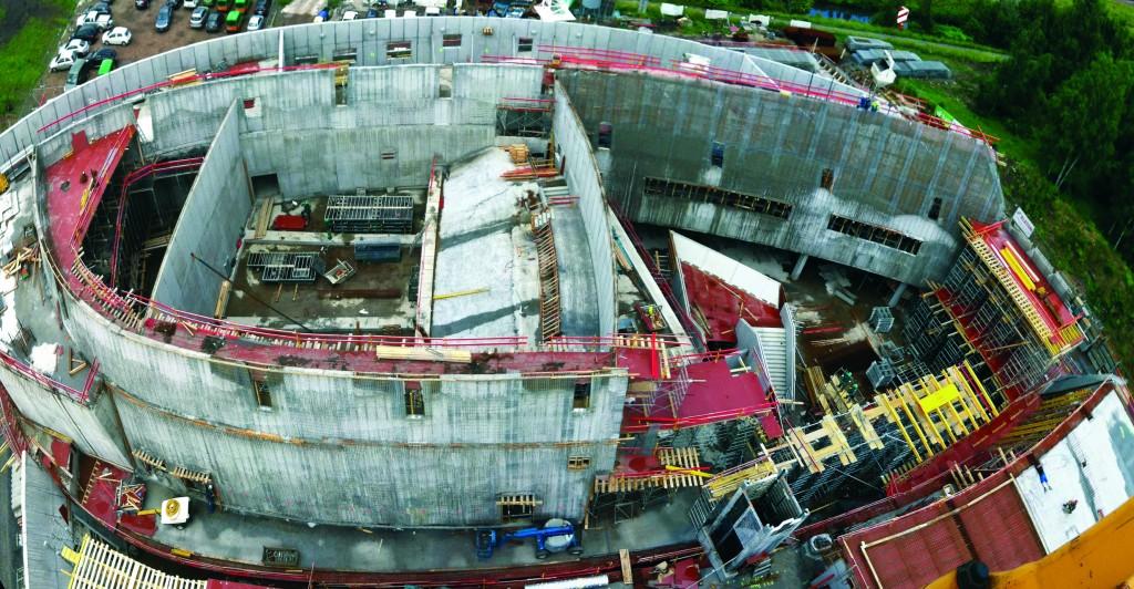
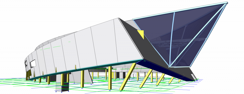
SCIA Engineer provides a comprehensive solution for modelling, analysis and design of composite floors. The software automates the two principal tasks that engineers need to tackle with in order to achieve a safe and executable design:
- the structural analysis of the floor inside a 3D FEM environment: including construction stages, partial composite action between beams and slab, and a specific handling of loads that is typical for this structural system;
- the code-based design of individual composite beams: checks for ultimate and serviceability limit states including an automatic design and shear connection arrangement.
What is more, the composite entities are integrated in advanced engineering design workflows: by modelling the slabs as well as the beams, it is now easy to represent rigid diaphragm behaviour, to capture nonlinearities. The engineer can employ stability, modal, seismic and second-order analysis with initial imperfections in order to understand the behaviour of the building as a whole.
Therefore, engineers can now use the same platform to create sophisticated models in a 3D CAE analysis environment and to run design checks and code-compliant optimisation on all or selected composite beams in these models.
Main advantages of SCIA Engineer composite floor solution
- A multi-model approach allows for checking of both construction and final (composite) stages at the same time without having to make modifications to the model.
- This staged analysis model also includes creep deformation and a partial shear connection between steel beams and a concrete slab. As a result, the FEM results represent the real deformation of the floor.
- Slabs can be represented by rigid, semi-rigid, or flexible floor diaphragms, depending on their stiffness and on your needs for a particular task or verification.
- The distribution of surface loads based on the tributary area method makes the results easier to understand and comparable to hand calculations.
- An automated handling of self-weight (i.e. increased weight of fresh concrete and higher safety factors related to it during execution) and load combinations make it easy to correctly take construction stages into account during the design.
- A comprehensive member verification is performed according to EN 1994-1-1 or AISC 360, including ULS and SLS checks for both the construction and the final stage.
- Detailing requirements ensure that the beams can be built on site and that the design methods remain applicable: the geometry of the steel beam and profile sheeting, the thickness of concrete topping, the position, diameter and spacing of shear connectors, and the reinforcement in the slab are all checked.
- Both code-based and user-defined spacing requirements for shear connectors are taken into account. This is important when the contractor sets special requirements for the execution on site.
- The final stage ULS bending moment resistance is based on a plastic stress distribution in the composite section, also taking into account partial shear connection.
- In the case of openings in the webs of steel beams, additional verifications are performed: according to SCI P355 in the Eurocode 4 context, and according to AISC Design Guide #2 in the AISC 360 context.
- The automatic design (AutoDesign) proposes a suitable cross-section, shear stud layout and camber (if needed) to cover all ULS, SLS and additional opening verifications for the construction and final phase, also taking into account detailing conditions.
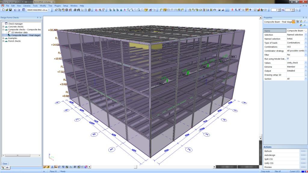
- Various available levels of output and visualisation in the 3D scene let the engineer create informative and scalable reports of the design.
- Rigorous floor vibration checks are available for composite beams designed according to AISC 360.
- A simplified check of the predicted natural frequency is performed in the case of Eurocode 4 verifications.
- Fire resistance checks according to EN 1994-1-2 for both the construction and final stage are available in the Eurocode environment.
Scope and limitations
- The composite beam functionalities described here pertain to the design of buildings.
- The steel beams must be prismatic and must have a symmetrical I-section: any I-profile (e.g., HE, UB, IPE, or sheet-welded) in the case of Eurocode 4 verifications, or a W-shape in the case of AISC 360 verifications.
- The composite slabs must consist of a profiled steel sheeting and a concrete topping. Solid slabs can be designed using workarounds with some conservative margin, using engineering judgement.
- The connection between the steel beams and the concrete slab is realised by headed studs.
- Only a single web opening per beam can be taken into account in the AISC 360 checks.
- The fire-resistance checks according to Eurocode 4 do not take web openings into account.
Modelling and analysis in 3D FEM context
The Composite Analysis Model (CAM) in SCIA Engineer analyses the entire structure during the stages of construction, service or maintenance. Stages are fully automated, which means that you can work as usual and in a linear context: for load combinations, analysis, results, etc. Deformations and load effects obtained from the different stages are superimposed, also taking into account the actual shear connection between beams and slab and the creep in concrete.
There are no limitations on the structural system or on the arrangement of beams: the composite beams may be simply-supported, continuous, or cantilevers, parallel to each other or with arbitrary orientation. The CAM detects which beams are primary and which are secondary based on the steel sheeting orientation. This is taken into account in the checks and AutoDesign later on.
The CAM derives the exact orthotropic properties of the corrugated steel sheeting and the concrete topping and uses these in the FEM calculations. The stiffness of the composite beams is augmented based on the degree of shear connection between beams and slab.
The effective width of composite beams is calculated automatically as well. The design codes EN 1994-1-1 and AISC 360-10 stipulate the width of concrete slab that contributes to the strength and stiffness of a composite beam. The following is detected automatically:
- the span length,
- the boundary conditions in the span in consideration and in neighbouring spans,
- the distance to neighbouring elements in the 3D model (i.e., other beams, walls, openings in the slab),
- the distance to slab edges.
For a more accurate stiffness estimation of e.g. cellular beams and other beams with openings, the CAM also takes into account all openings in the webs of the steel beams. Web openings modelled on 1D members are later on considered in the design modules. Cellular beams can also be designed using the Cellbeam design tool by the British fabricator Westok. A bi-directonal link is available between SCIA Engineer and Cellbeam for export and import of both steel and composite beams.
Construction stages
Internally, the software manages three FEM submodels with different stiffness of the composite slabs – one for the construction stage and two for the final composite stage: with long-term and short-term stiffness. The stage-based model includes rheological effects (i.e. creep) by distinguishing between long and short-term load cases in the final (service) phase.
The engineer can let the software fully manage load cases or combinations between the different stages, or he/she may manage them manually. In addition, the software automatically takes into account that fresh concrete weighs more during the construction stage due to its higher water content. Fresh concrete is also considered as a variable load with appropriate safety factors. This is due to the delivery methods and the fact that liquid concrete can heap in specific areas of the slab and on individual beams.
Compatibility with design codes
Two mathematical formulations of the composite slab with steel beams are supported. The default one ("standard composite action") allows us to avoid normal forces from the eccentricity between the slab and beams in the FEM model. This idealisation is suitable for the majority of design tasks and is the only one compatible with the design methods described in AISC 360 and Eurocode 4. In this formulation, bending moments in the beams are increased and match simplified load descending methods usually used in hand calculations.
The second formulation ("advanced composite action") is based on the actual cross-section properties and alignment of the beams. As a result, normal forces are generated in both the beam and the deck as a result of the eccentric placement of the 1D member. The latter approach is useful for more advanced analysis of the whole composite structure.
Load: diaphragms and tributary areas
Rigid in-plane diaphragms combined with tributary area distribution for gravity loads offer a good approximation of the actual behaviour of composite floors. These two modelling features let you to obtain clear and verifiable results while reducing computation time.
Rigid diaphragms simplify the analysis model based on reasonable assumptions that are verified by decades of engineering experience. Lateral loads are distributed to vertical load-bearing elements based on their stiffness, while gravity loads are distributed to the floor beams based on tributary areas. Results obtained from such a numerical formulation of the composite slab are directly comparable to hand calculations and parasitic moments in various parts of the structure are avoided.
Flexible diaphragms are useful for the modelling of steel decking roofs. Such roofs are often found in buildings where the floors are composite but adding of a concrete slab for the roof is, in most cases, not financially justified.
Semi-rigid diaphragms are a good solution when you want to use the tributary area load distribution method for gravity loads but would like to keep the FEM formulation for lateral loads. This is often needed in the case where openings in the slab compromise the lateral rigidity of the floor in certain parts.
Libraries
The following libraries simplify the definition of a composite floor:
- a steel sheeting library with common decking from European, British and North American manufacturers;
- a shear stud library.
During modelling, you select products from the library or defines decking or studs manually. You can further extend the decking library with their own sheets. Filtering based on various criteria (e.g. the manufacturer or a wildcard) is also available.

Code-based design according to EN 1994-1-1
The design of composite beams is performed according to EN 1994-1-1 and relevant parts of EC2, EC3 and a number of Steel Construction Institute (SCI) publications on the topic. The following is included:
- Ultimate and serviceability limit states are checked for both the construction and the final composite stage.
- Primary and secondary beams are recognised and treated differently when, e.g. determining the stud arrangement.
- The concrete slab contribution to the resistance of steel beams in the final stage is taken into account via effective width that varies along the beam length.
- Section classification is based on the actual position of the neutral axis in the composite cross-section.
- Shear studs design is based on ULS considerations and detailing; you may also input a stud spacing manually, and have it verified. Additional checks of stud placement are performed when significant point forces are present on the beam.
- Camber can be designed or inputted (as an absolute value or as a value relative to the span length).
- Eurocode national annex parameters are supported.
- The headed stud resistance is modified according to the SCI publication “NCCI PN001a-GB: Resistance of headed stud shear connectors in transverse sheeting” when the UK National annex is selected. This takes into account the geometry and behaviour of more modern steel sheeting and complies to both the Eurocode 4 and the engineering practice in that region.
- You may define multiple openings in the steel beam web; in this case, additional checks are performed according to SCI P355 “Design of composite beams with large web openings”. Circular, rectangular, and elongated openings are supported, reinforced or not.
- A more economic design may be achieved by reducing composite action below the limitations of EN 1994-1-1: you can design studs according to SCI 405: Minimum degree of shear connection rules for UK construction to Eurocode 4.
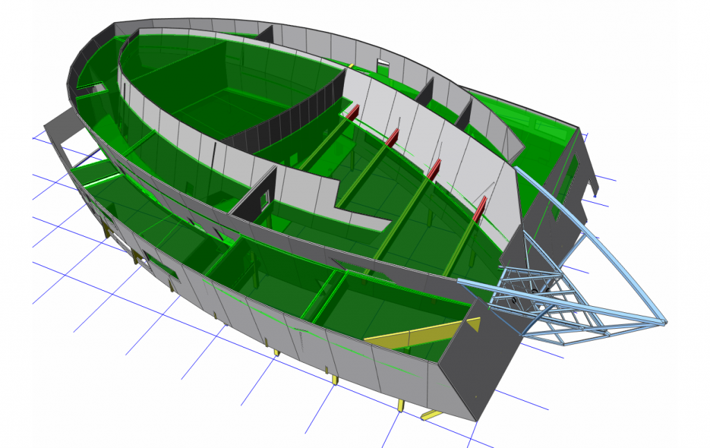
- The check results can be plotted on the beams in the 3D scene and listed in Table Results. Error, warning and note indicators and design summaries are plotted directly on the beams in the 3D scene.
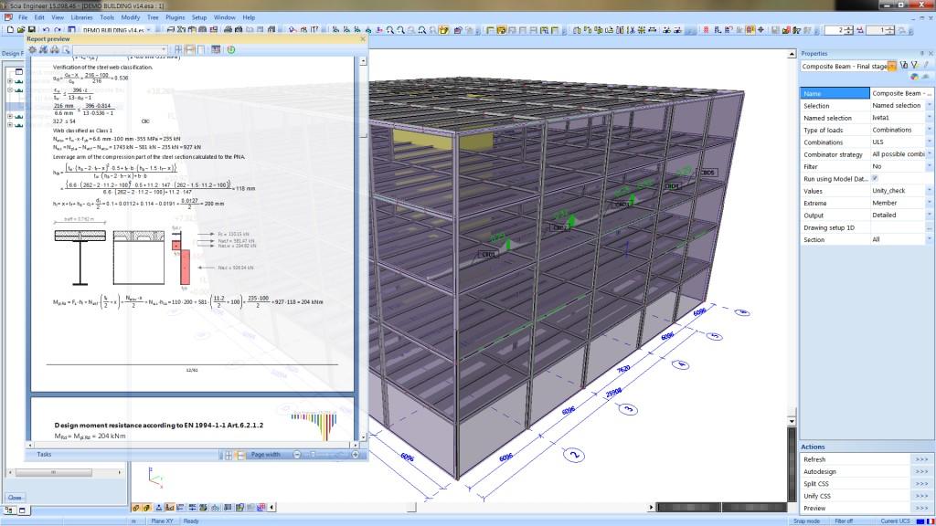
- There are three levels of detail in the output, thus ensuring scalability of the final report: you select the right output variant based on the particular needs: the Brief output summarises the design in a single table row, the Standard output summarises the main milestones of the design, while the Detailed output provides a description of the calculation with rendered formulas, intermediate calculation steps, and images made to scale.
As already indicated above, cellular beams can also be designed using the Cellbeam design tool by the British fabricator Westok. A bi-directonal link is available between SCIA Engineer and Cellbeam for export and import of both steel and composite beams.
The following checks are performed:
- Positive and negative flexural capacity of the composite beams (evaluated as per EN 1994-1-1, Chapter 6);
- Section classification of the steel beam in the composite stage (as per EN 1993-1-1, 5.5.2);
- Shear connector capacity and effect of number and strength of connectors on the overall beam resistance (evaluated per EN 1994-1-1, 6.6.4);
- Verification of longitudinal shear (as per EN 1994-1-1, 6.6.6.4);
- Verification of crushing of concrete flange (as per EN 1992-1-1, 6.2.2 (6));
- Shear capacity and shear buckling of composite beams (evaluated per EN 1993-1-1, 6.2.8 based on the steel section);
- Additional checks on minimal degree of shear connection, minimum area of longitudinal reinforcement as per EN 1994-1-1 5.5.1(5), etc.
- The calculated minimal reinforcement is compared to the one provided by the user and a warning is issued if both the bar diameter and bar spacing do not comply with the recommendations of EN 1994-1-1, §7.4. 3.
Automatic design
The AutoDesign routine cycles thought all ultimate and serviceability checks and detailing conditions in the construction and final stages, and proposes suitable cross-sections, stud layouts, and camber values that fulfil all design code requirements, also in the case of web openings on the beams. The resulting solution is economical, yet safe; limit states and detailing are fulfilled in one go.
The optimisation is controlled by you in the following ways:
- You select an "optimisation strategy:" to either minimise the steel beam size (thus using more studs), or minimise the number of studs (resulting in larger steel beams) or a balanced approach.
- You can limit beam height: useful if the floor height is limited.
- You may define a maximal value of camber that may be used to counteract serviceability issues.
- It is easy to split previously grouped members based on their utilisation levels (so that these can be optimised separately).
- SCIA Engineer determines the shear connection between the beams and the slab based on an ideal stud layout (as adopted in the checks and reported in the output) and uses this in subsequent analysis.
- It is also possible to unify groups of members that converge to the same design solution.
- You can specify that the routine should switch to 2 studs per row if higher shear connection is needed.
- For primary beams, both a uniform and segmented stud layouts are provided.
The AutoDesign is limited to hot-rolled I-sections from the Profile Library (user-defined extensions are supported). Sheet-welded sections are only checked; nevertheless, stud and camber design are performed for welded sections.
Structural fire design according to EN 1994-1-2
Fire safety verifications are performed according to EN 1993-1-2 & EN 1994-1-2 for the construction and final stage.
- The anticipated fire duration, fire protection and exposure are defined per composite beam.
- The evolution of air temperature over time is calculated according to ISO 834.
- The temperature evolution in the steel and concrete parts is determined by splitting the steel beam into flanges and a web, and splitting the concrete slab in the heat-affected zones into layers of 10 mm.
- The bending and shear capacity of the beams is determined based on the calculated temperature and heat-dependent material properties. Failure in longitudinal shear and crushing in the concrete slab are likewise performed in the final stage.
Code-based design according to AISC 360
The design of composite beams is performed according to the AISC 360-16 standard and includes the following:
- Strength and serviceability limit states are checked for both the construction and the composite stage. Both the Load and Resistance Factor Design (LRFD) and the Allowable Strength Design (ASD) methods are supported for strength verifications.
- The concrete slab contribution to the resistance of steel beams in the final stage is taken into account via effective width.
- Positive and negative flexural strength is evaluated per AISC 360-16, Chapter I2.
- Shear strength (including shear buckling) is evaluated per AISC 360-16, Chapters I4 & G2.
- The strength of shear connectors is evaluated per AISC 360-16 Chapters I3b & I8.
- Detailing provisions (related to the concrete slab, steel deck and shear studs) are taken into account per AISC 360-16 Chapter I.
- Primary and secondary beams are recognised and treated differently when, e.g., determining the stud arrangement.
- Shear studs are designed based on strength considerations and detailing or you may input the stud spacing manually, and have it verified. Additional checks on the studs placement are performed when significant point forces are present on the beam.
- Camber can be designed or inputted (as an absolute value or as a value relative to the span length).
- You may define an opening in the steel beam web; in this case, additional checks are performed according to AISC Design Guide #2: Steel and Composite beams with web openings. Circular and rectangular openings are supported, reinforced or not.
- The check outcome can be plotted on the beams in the 3D scene and listed in Table Results. Error, warning and note indicators and design summaries are plotted directly on the beams in the 3D scene.
- The performed verifications are described in three levels of output ensuring scalability of the final report: you select the right output based on the particular needs at hand: the Brief output summarises the design in a single table row, while the Detailed output provides a description of the calculation with rendered formulas and intermediate calculation steps.
Automatic design
The AutoDesign routine cycles thought all ultimate and serviceability checks and detailing conditions in the construction and final stages, and proposes suitable cross-sections, stud layouts, and camber values that fulfil all design code requirements, also in the case of web openings on the beams. The resulting solution is economical, yet safe; limits states and detailing are fulfilled in one go.
The optimisation is controlled in the following ways:
- You select an "optimisation strategy:" to either minimise the steel beam size (thus using more studs), or minimise the number of studs (resulting in larger steel beams) or a balanced approach.
- You can limit beam heights: useful if the floor height is limited.
- You may define a maximal value of camber that may be used to counteract serviceability issues.
- It is easy to split previously grouped members based on their utilisation levels (so that these can be optimised separately).
- It is also possible to unify groups of members that converge to the same design solution.
- You can specify that the routine should switch to 2 studs per row if higher shear connection is needed.
- For primary beams, both a uniform and segmented stud layout are provided.
The AutoDesign is limited to hot-rolled wide-flange W-shapes.
Floor vibration checks
Floor vibration checks can be performed on composite beams separately from the verifications described above, following the methods prescribed in the 2016 AISC Design Guide 11: Floor Vibrations Due to Human Activity.
This functionality lets engineers deal with a serviceability limit state that often dominates the design of composite floors: floor vibration often interferes with human comfort when not addressed, due to the light weight of the composite floor structural system.
- A quick and sufficiently accurate verification for walking-induced floor vibrations is offered based on established design methods from the United States.
- The dynamic response of the floor is predicted assuming full composite action between beams and slab and an increased Young's modulus of concrete. The interaction between primary and secondary composite beams is taken into account.
- Acceleration levels are compared with tolerance levels for human comfort, taking into account the function of the floor.
- These verifications follow a check logic, rather than requiring modal analysis: this simplifies and greatly speeds up the control of vibrations, giving a good estimate of the actual response of the floor.
The module Composite Steel-Concrete columns EC4 is a module for structural design and code-checking of composite columns. It calculates their strength, stability and stiffness in accordance with EN 1994 for buildings.
Several checks are performed according to the ultimate limit state: resistance of members in axial compression, combined compression and uniaxial bending, combined compression and biaxial bending and influence of transverse shear on resistance to bending. Furthermore, the resistance calculation of a composite column in a fire situation is included in this module too.
Composite columns composed of concrete-filled steel tubes (CFT) have become increasingly popular in structural applications around the world. This type of column can offer many advantages, such as high strength, ductility, and large energy absorption capacity, as well as increased speed of construction, positive safety aspects, and possible use of simple standardized connections. Furthermore, today's possibility to produce concrete grades with higher compressive strengths allows for design of more slender columns, which results in larger floor space.

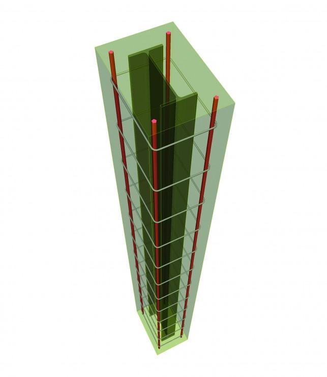
Composite Column Sections
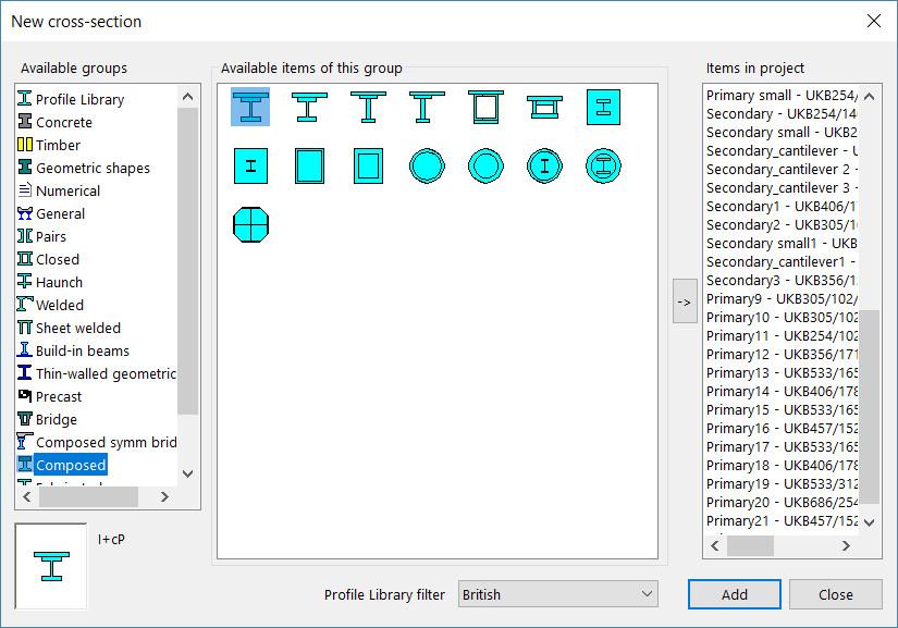
Design checks can be carried out for six rolled or welded types of composite sections as illustrated in the image below.
Methods of analysis
Composite design checks can be carried out for both a linear and a non-linear combination. Parameters involved in the check that are unique to linear / non-linear combination are discussed for both type of calculations.
Linear combination
- Second order effects: The applicability is checked according to clause 5.2.1(3) of EC-EN. If applicable, these are incorporated in accordance with clause 6.7.3.4(5).
- Member imperfection moments: The influence of geometrical and structural imperfections is taken into account through the equivalent member imperfections as mentioned in table 6.5.
- Modified moment: The moments obtained from the linear static analysis are modified on the basis of the second order moments and imperfection moments are calculated as stated above.
Non-linear combination
- Second order effects: these are not taken into account in the non-linear calculation
- Member imperfections: If the non-linear analysis is carried out without considering the imperfections in the analysis then these imperfections are accounted for in the design check in accordance with Table 6.5; else if the non-linear analysis is carried out considering the imperfections then these imperfections do not form a part of the design check.
- Modified moment: The moments obtained from the non-linear analysis are modified by adding the imperfection moments if the same are not incorporated in the analysis.
- Axial check: It must be noted that in the case of an axial check for a non linear combination, no separate buckling check is carried out. That means that the axial resistance is taken as the plastic moment of resistance of the composite section (obtained as described in section 4.1.1 below) and the corresponding utilization is defined as the ratio of axial force at the section to the plastic resistance to compression.
Design checks: Ultimate limit state
The checks are performed according to EN 1994-1-1:2004.
The design checks for composite column sections are based on the simplified method of design which is applicable to prismatic column sections with doubly symmetric sections. Different checks are performed.
Resistance of members in axial compression
This type of check contains:
- The plastic resistance to compression of the composite section
- Calculation of the elastic critical normal force
- Calculation of the effective flexural stiffness
- The influence of long-term effects: reduction of the modulus of elasticity of concrete
- Use of European Buckling curves
- Calculation of non-dimensional slenderness
- Evaluation of the buckling resistance to compression
- Calculation of the utilisation ratio for the resistance in axial compression
Combined compression and uniaxial bending
The resistance of a member to combined compression and uniaxial bending is evaluated by means of an interaction curve (clause 6.7.3.6)
Combined compression and biaxial bending
The resistance of the section under combined compression and biaxial bending is evaluated according to clause 6.7.3.7 equation 6.47.
Influence of transverse shear on resistance to bending
The influence of transverse shear forces on the resistance to bending and normal force is considered when determining the interaction curve as per clause 6.7.3.2(3)
Shear resistance
Longitudinal shear at the interface between concrete and steel is verified in accordance with clause 6.7.4.3
Design checks: Fire exposure
For the fire resistance calculation refer to EN 1994-1-2:2005 .
Following are the calculation models used to check the resistance of a column in a fire situation:
- Fully concrete encased sections: Check in accordance with the Tabulated data in Table 4.4
- Partially concrete encased sections: Balanced summation model as described in Annex G.
- Concrete filled circular hollow sections and concrete filled rectangular (or square) hollow sections: Generalised design method as described in clause 4.3.5.1 as well as the alternative design method described in Annex-H

Want to try SCIA Engineer yourself?
Explore how our software and services can help you optimise your work and boost your productivity. Try it for yourself with a free 30-day software trial.
Download a free 30-days full trial