Automatically design reinforcement in beams, ribs and columns
Design of reinforcement can be a tedious task in large models. SCIA Engineer offers an automated workflow to design the longitudinal as well as shear reinforcement.
1. Evaluation of internal forces
Command: Main menu > Design > Concrete 1D member > Internal forces for design OR Workstations > concrete > internal forces for 1D reinforcement design
Before you start with the design of reinforcement, it’s important to verify that the internal forces that will be used in the design procedure are reasonable and logical in terms of their magnitude and distribution and that they correspond to the assumptions of the model.
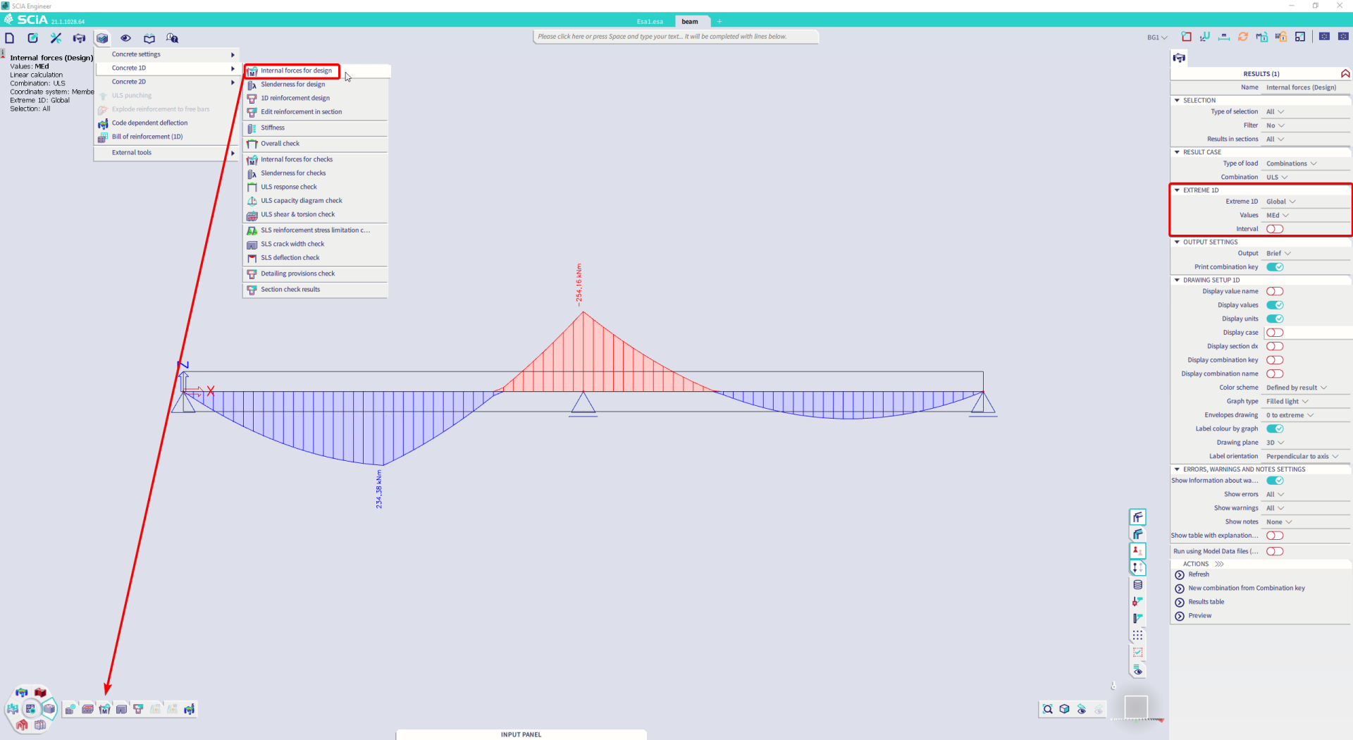
Fig.1 Evaluation of internal forces
2. Definition of a template for provided reinforcement
Command: Main menu > Design > Concrete settings > settings OR Workstations > Concrete > Concrete settings
In the design of reinforcement itself, you first need to select a suitable reinforcement template. In the template you specify the basic reinforcement (typically the corner beams) that is used along the whole length of the element. In addition, you also define parameters for the reinforcement that is added in sections of the element where the basic reinforcement is insufficient.
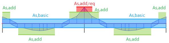
Fig. 2 Types of provided reinforcement
- As,basic = basic reinforcement
- As,add = additional reinforcement
- As,add,req = additional required reinforcement = the reinforcement that cannot be placed in the section using the selected template, which means that the template (in fact the reinforcement layout) needs to be adapted
In the reinforcement template you define the diameter of reinforcement bars, their maximum number in one layer, distance between stirrups, etc. The same approach applies to both longitudinal and shear reinforcement.
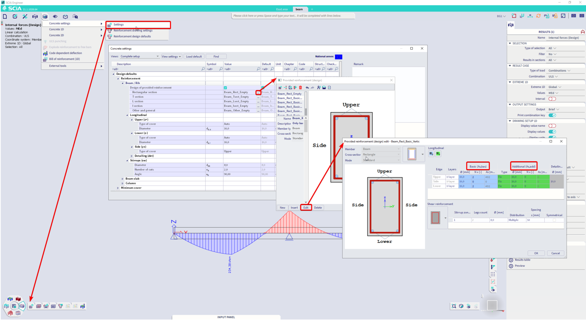
Fig. 3 Input of provided reinforcement
3. Design and verification of provided reinforcement
Command: Main menu > Design > Concrete 1D > 1D Reinforcement design OR Workstations > Concrete > 1D reinforcement design
The program then uses the selected template to automatically place the reinforcement into individual beams and verifies whether the selected template is sufficient for all places in the structure.
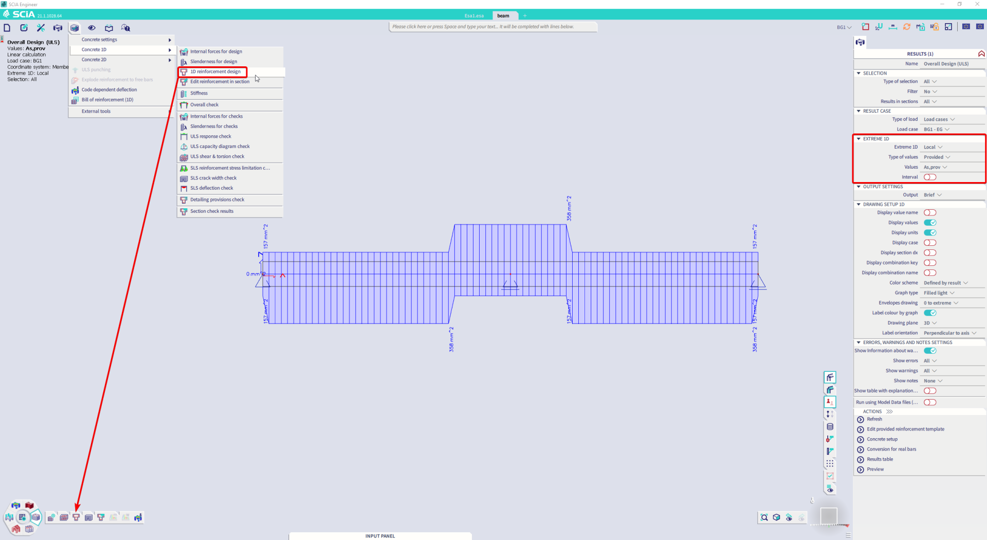
Fig. 4 Designed amount of provided reinforcement expressed as a number and diameter of bars (e.g. 2 ø 12 + 2 ø 16)
If the template is insufficient, the program determines the amount of reinforcement that must be added in the critical places (denoted as As,add,req). In that case you must adapt the reinforcement template and perform the design again.
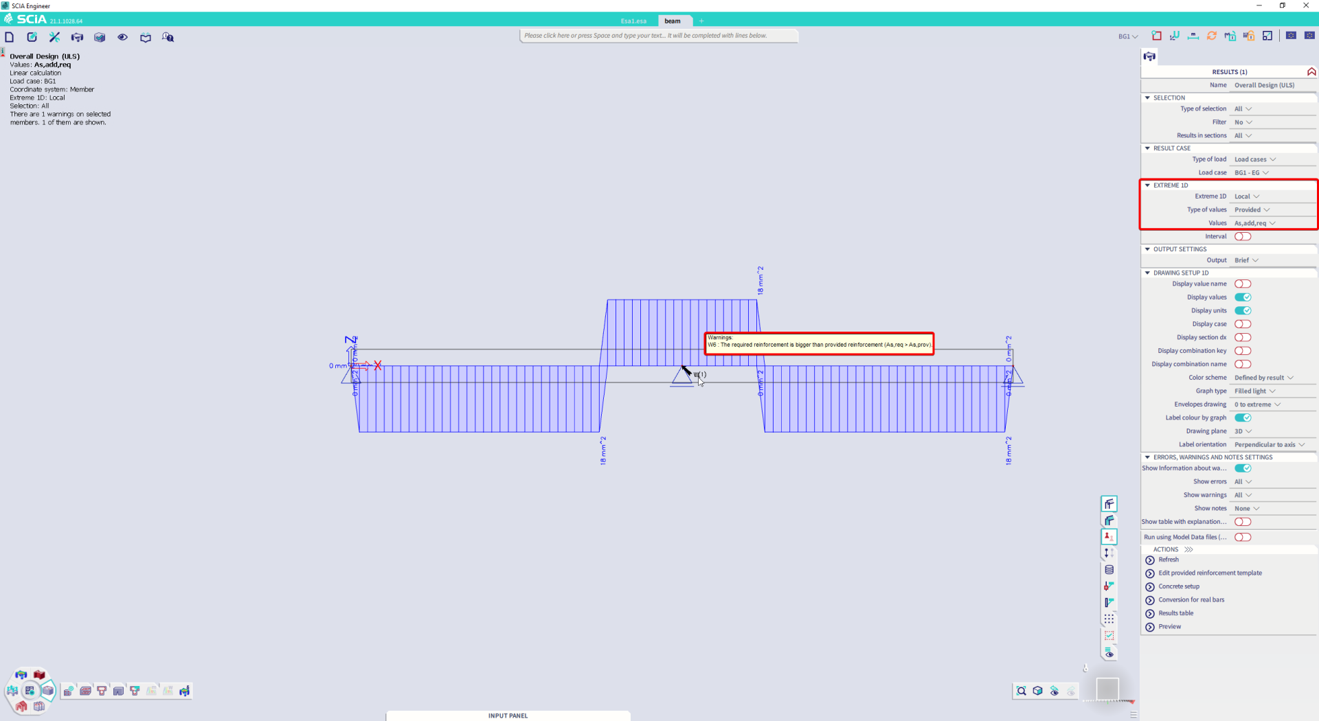
Fig. 5 Calculated amount of additional required reinforcement
UC (As,req) values
You can verify the sufficiency of the template (i.e. whether it fully covers the required amount of reinforcement) also using the Reinforcement design command in which you select the UC (As,req) values. This command calculates the ratio of the required and provided (template) reinforcement. The places where the template is insufficient (i.e. the places where the amount of the required reinforcement is greater than the amount of the provided reinforcement) are displayed in red colour.
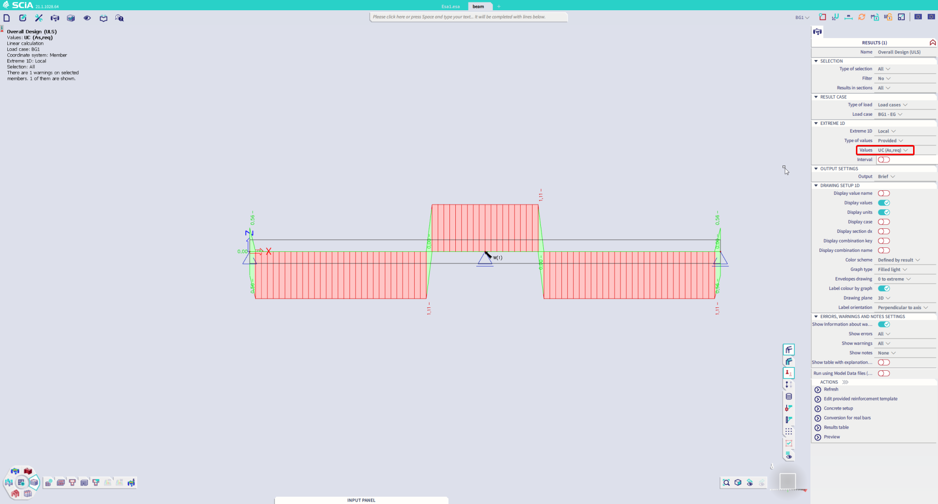
Fig. 6 Verification of the template’s sufficiency
UC(As,max) values
In addition, you can also verify whether the reinforcement designed using the selected template complies with code-specified detailing provisions. For this, select the UC(As,max) values in the Reinforcement design command. This command compares the provided (template) reinforcement with the maximum amount of reinforcement complying the code-specified detailing provisions.
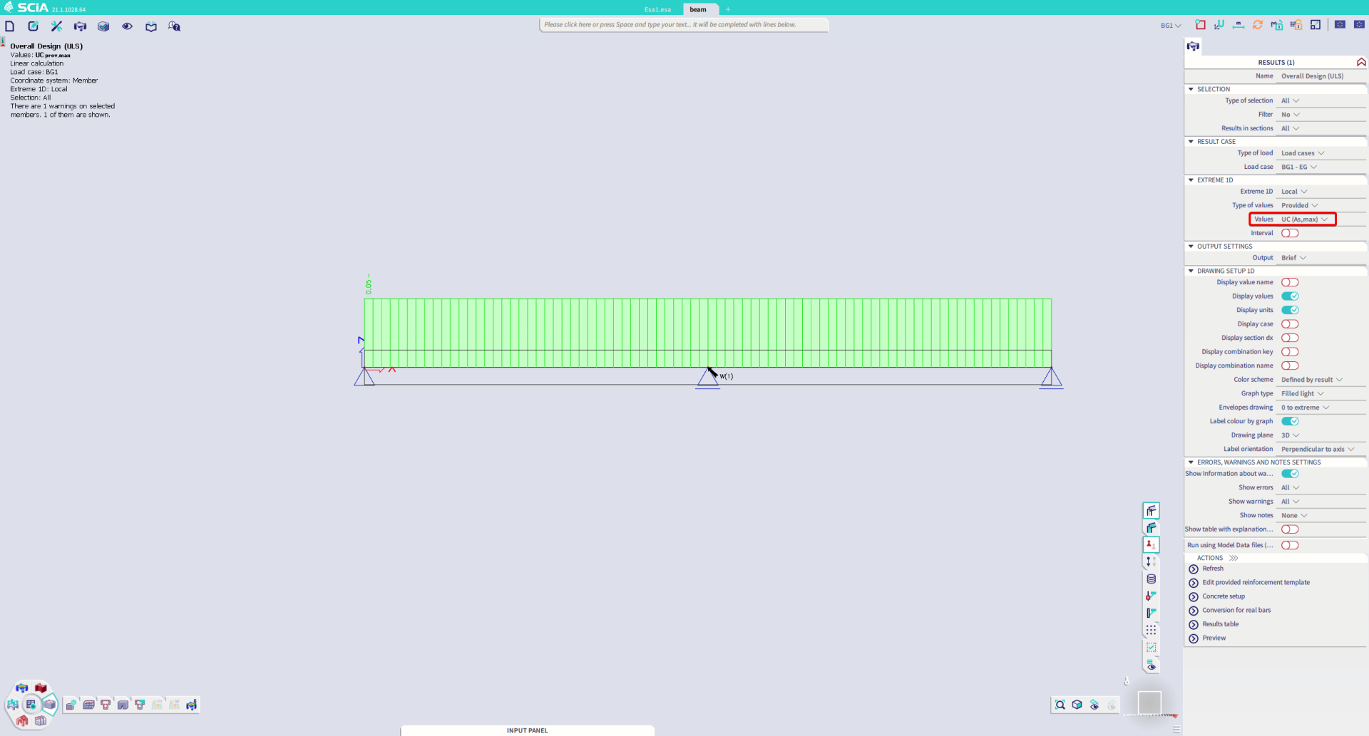
Fig. 7 Verification of detailing provisions
As already indicated above, an analogous procedure applies also to shear reinforcement.
4. Conversion of provided reinforcement to “real” 3D reinforcement bars
Command: Main menu > Design > Concrete 1D > 1D Reinforcement design OR Workstations > Concrete > 1D reinforcement design
Action button: Conversion for real bars
Up to now, when talking about the design of reinforcement, we were considering a specific number of bars of a specific diameter. Individual reinforcement bars have not been displayed graphically in the 3D model. We can examine the moment diagrams, we can read how many bars of which diameter are needed in every place in the structure, but we cannot see the individual “real” reinforcement bars. To see them, we need to convert the provided reinforcement into the 3D reinforcement bars (longitudinal bars and stirrups). This conversion is automatic, and it takes account of practical requirements like symmetry of reinforcement above supports, minimal length of bars, etc.
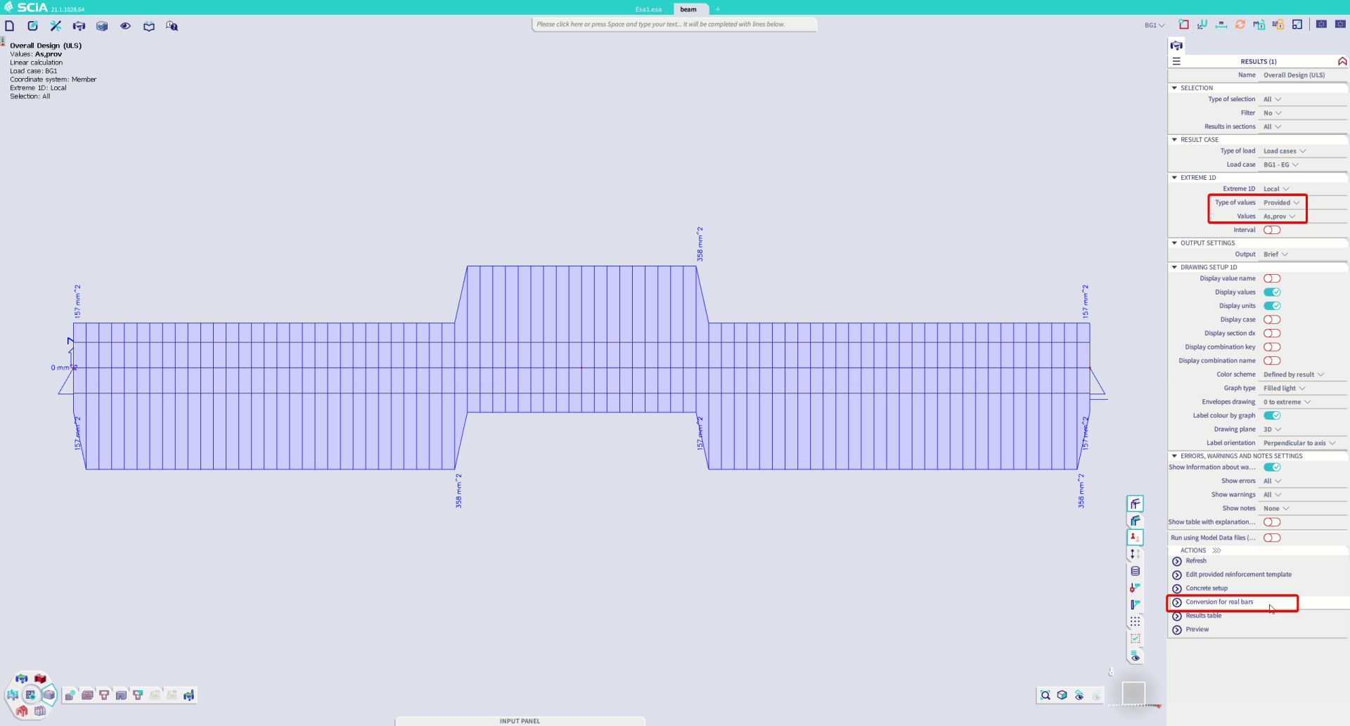
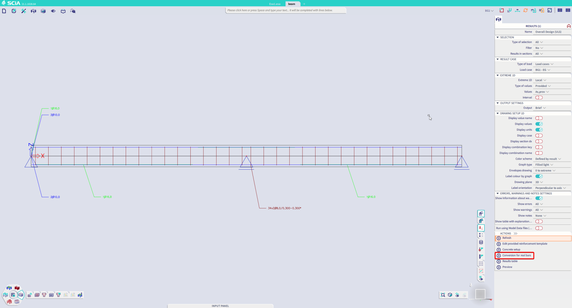
Fig. 8 Conversion of the provided reinforcement to “real” 3D reinforcement bars
Once the reinforcement is converted, we can not only display the reinforcement bars in the graphical window (and Engineering Report too), but we can perform a whole set of checks for the ultimate and serviceability limit states.