Model a composite deck
The composite deck is a slab with a significant in-plane stiffness that still distributes the gravity loads to the beams below it based on tributary areas. Since SCIA Engineer 17 is possible to model composite deck with four ways of slab behavior:
- Standard FEM
- Flexible diaphragm
- Semi-rigid diaphragm
- Rigid diaphragm
Note: For modeling of composite ceiling it is necessary to have selected material concrete and steel in the Project data.
The concept is simple. We are talking about a load panel with realistic in-plane stiffness. Although a composite slab has a significant thickness, due to the specific behavior of this structural system, users prefer that each beam takes the load applied directly on top of it. Or strictly speaking, applied on the area measured between the midlines between the beams.
The presence of bending stiffness in the slab would prohibit such simplified load distribution: it would be the stiffness (read also ‘deformations’) of the beams and slab that would determine how much load will go where. In this case, even if you apply the load directly on the beams, an edge beam would not carry half of the load of an internal beam. See the image below: the FEM formulation results in varying values between equally spaced beams.
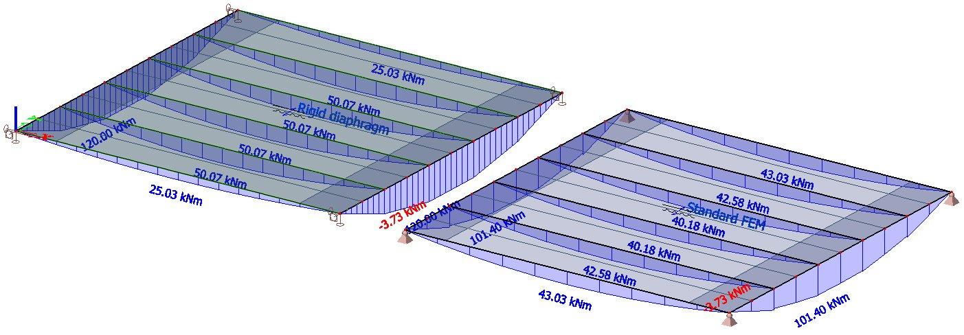
Figure 1: Bending moments in composite floor beams: (left) a rigid diaphragm with tributary area action; (right) load distributed based on the FEM formulation of the composite slab.
Does it mean that the “tributary area” simplifying assumption is inaccurate?
Actually, it is the FEM approach that ignores nonlinearities such as cracking of concrete, shear connectors, structural gaps between columns and decks, etc., unless they are explicitly defined in the model. The tributary area method, although a simplification, is based on decades of engineering experience, and tries to address a number of engineering problems in the material and the geometric response that would overcomplicate the design if modeled precisely.
In short, diaphragms allow the user to split the response to lateral loads from the response to gravity loads. Several possibilities exist to tweak the FE model for various use cases. For example, you may choose to model a flexible diaphragm steel deck that supplements the rotational stiffness of attached beams but does not provide significant diaphragm action. The type of gravity load transfer, in this case, is completely up to you: a FEM-based load panel, tributary areas, or simply the actual stiffness of the sheeting. The last one even lets you directly control the deflections of the deck.
The description of individual slab behavior
Standard FEM
Users will find their familiar FEM plates by selecting the “Standard” Element type in the 2D member properties. The standard 2D member has the bending and in-plane stiffness derived from its geometry and assigned material. This option is great for analysis of concrete plates and flat slabs.
Rigid diaphragm
A rigid diaphragm does not use a finite element mesh. It has no bending stiffness. Loads perpendicular to it are transferred to the supporting elements in the same way as for a load panel. Its in-plane stiffness is infinite because no relative in-plane deformations can happen between any two points of the diaphragm.
In previous versions, users used to simulate the rigid diaphragm action by introducing rigid links between, for example, all nodes of a 2D member, or between all column nodes in a floor. This workaround is no longer necessary.
No stresses and deformations can be obtained inside rigid diaphragms because they have no physical stiffness. Therefore, the rigid diaphragms are suitable for the analysis of composite steel-concrete floors. For these, the design of the deck itself is usually based on manufacturer sheets, where the correct sheeting is selected according to the thickness of the deck and the load acting on the floor.
Semi-rigid diaphragm
A semi-rigid diaphragm is a hybrid between the standard FEM plate and a load panel. The actual in-plane stiffness of the 2D member is used in the analysis, but the bending stiffness is eliminated. Gravity loads are transferred like by load panels.
This type of 2D members is suitable for the analysis of composite slabs when the user is not sure about the rigid-body nature of the deck. In the case of large openings, parts of the floor could remain as narrow strips, which are less stiff under an in-plane loading. In this case, the diaphragm action could be compromised, and it is advisable to work with the actual stiffness parameters of the floor and to control deformations.
Flexible diaphragm
Flexible diaphragms are most suitable for the analysis of metal deck floors (sheeting only). The diaphragm action is negligible here. Numerically, this is achieved by eliminating the shear stiffness in the plane of the 2D member. As a result, the lateral loads are distributed to the vertical load bearing elements using an approach similar to tributary areas, independently on the relative stiffness of the various columns and walls. The gravity loads are distributed like by load panels.
Flexible diaphragms are most suitable for the analysis of roofs in composite buildings, where a concrete layer is not poured, or floors in industrial steel buildings, where sheeting or other types of metal plates are used to construct the floor.
Comparison of individual diaphragm types
This section shows a comparative example of the analysis of a composite floor using various types of diaphragms.
The structure is a 2-bay composite floor supported by six columns. A concentrated horizontal load is applied along the edge beam, near the center column, with a small eccentricity. The first model uses a rigid diaphragm, the second one a semi-rigid diaphragm, and the third one a flexible diaphragm. The deformed shapes are presented in top view. To emphasize the specific behavior of each type of diaphragm, the deformation scale has been adjusted separately for each model.
Rigid diaphragm
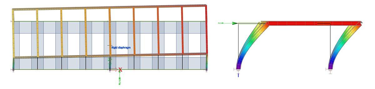
Figure 2: Rigid diaphragm.
A rigid diaphragm is perfectly rigid in its own plane. It is visible here that the eccentric load results in the diaphragm slightly rotated as a rigid body with its rectangular shape perfectly kept. The displacement of the floor is entirely due to the deformation of the columns.
Semi-rigid diaphragm
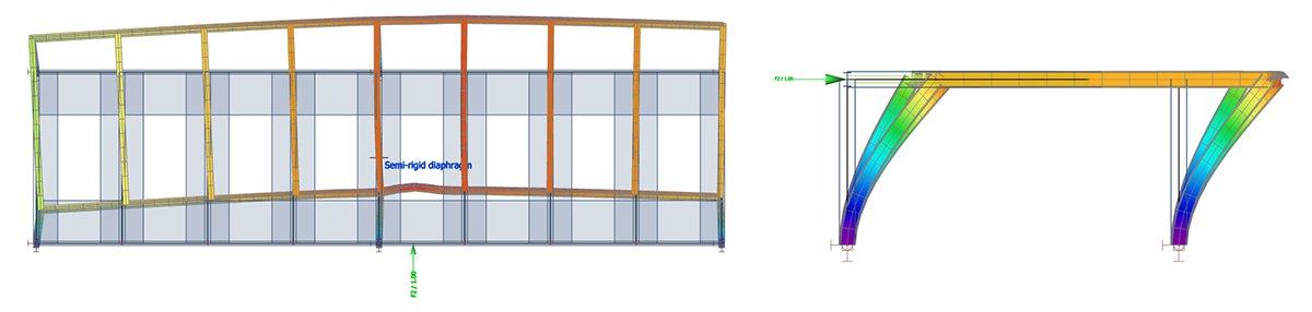
Figure 3: Semi-rigid diaphragm.
A semi-rigid diaphragm uses the real in-plane stiffness of the deck for the analysis. In this case, the displacements are due partly to the deformations of the diaphragm and partly to the deformations of the columns. The initial rectangular shape of the deck is not kept (slight in-plane curvature) and a bump is visible in the beam where the load is applied.
Flexible diaphragm
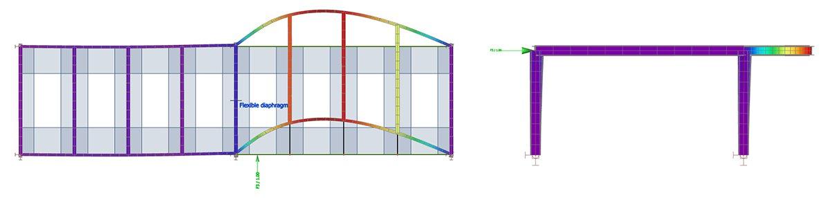
Figure 4: Flexible diaphragm.
A flexible diaphragm has no in-plane shear stiffness. Therefore, it cannot act as a rigid body. It can only transfer axial forces. The displacements are mostly due to the deformation of the beams that are much more flexible than the columns in this particular case. The floor is entirely deformed by the applied load.