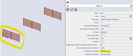
Load transfer method on load panel
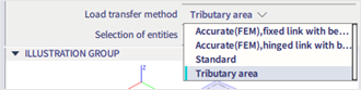
Different methods are available for the loads transfer via load panels :
Which one to choose?
By default, the method is « Tributary area » : loads are distributed according to the break lines.
But this method is available only with uniform surface loads on the whole panel.
In case of partial surface loads on a panel, or triangular loads, or trapezoidal loads, …, a warning will be displayed because we need to use another method.
Standard
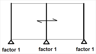
The load is distributed according to factors.
In the above example, the load would be distributed by 1/3, 1/3, 1/3 on each bar, because factor 1 is defined on each bar (even if the load is a linear or a point load in a corner of the panel).
The distribution doesn’t take into account the loads locations, but rather the defined factors.
This method is less used than the others.
Accurate (FEM) - all load transfer directions
When you use a load panel with the Load transfer method “Accurate (FEM), following analysis is performed (see also our helppage FEM method):
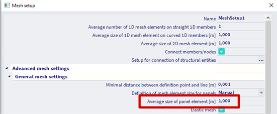
The solver uses the mesh setting 'Average size of panel elements [m]':
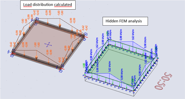
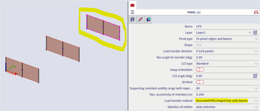
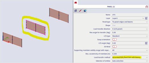
For the FEM load transfer methods, there are options 'hinged support' and 'fixed support'. The distribution of loads is done following the indicated, giving for example the following results:
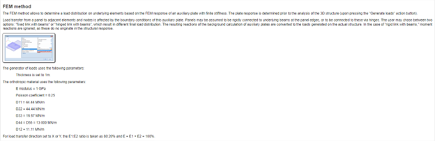
The analysis is done with fictive 2D elements with the following parameters:
- E modulus = 1 GPa
- Poisson coefficient = 0.25
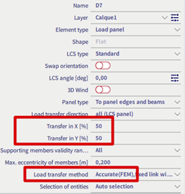
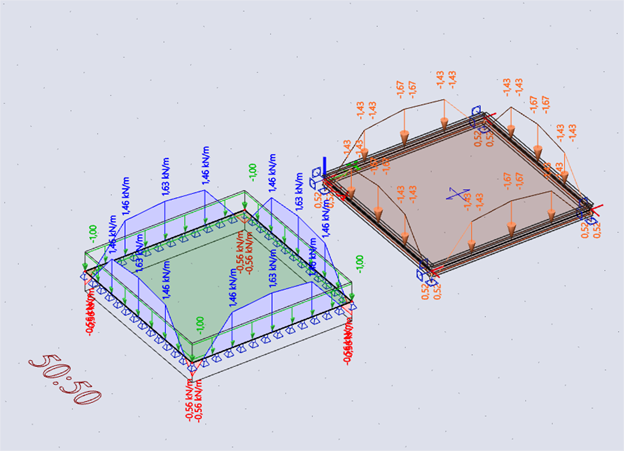
Accurate (FEM), fixed link with beams, X and Y 50%
Accurate (FEM), hinged link with beams, X and Y 50%
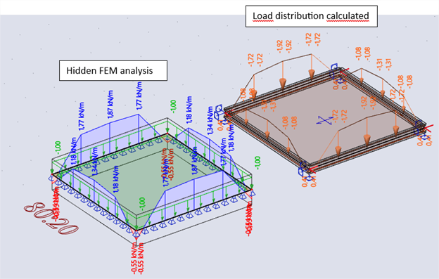
Accurate (FEM) - 1 direction
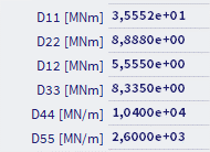
If the load transfer direction X and Y are set differently, for example 80% and 20%, then the parameters of the orthotropy are calculated proportionally.
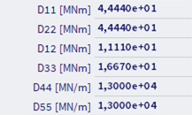
For load transfer direction set to X or Y, the E1:E2 ratio is taken as 80:20% and E = E1 + E2 = 100%.
- D11 and D44 = 80%
- D22 and D55 = 20%
- D12 and D33 = 50%
Accurate (FEM), fixed link with beams
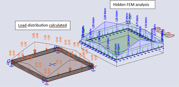
Accurate (FEM), hinged link with beams
Example on a simple structure
In the case of a panel with identical spans and a uniform load, manual verification is easily feasible using structural mechanics formulas.
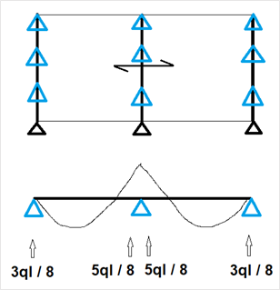
Accurate (FEM), fixed link with beams
This method is close to the tributary areas method, because the distribution is divided by 2 on each side.
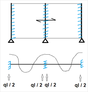
Accurate (FEM), hinged link with beams
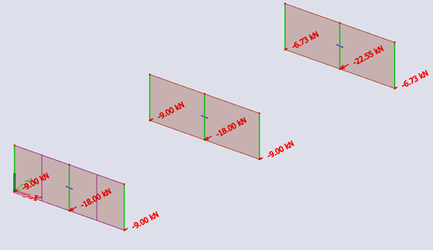
Let’s have a look at the simple example below:
Let’s apply a surface horizontal load on each panel.
Results are in line with the previous description of this option: