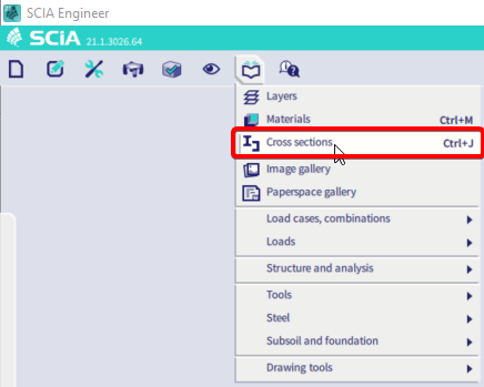
Import a cross-section from a dwg or dxf file
In SCIA Engineer a cross-section in DXF or DWG format can be imported (module sen.05 General cross-section editor is necessary). The following steps describe how to do this properly.
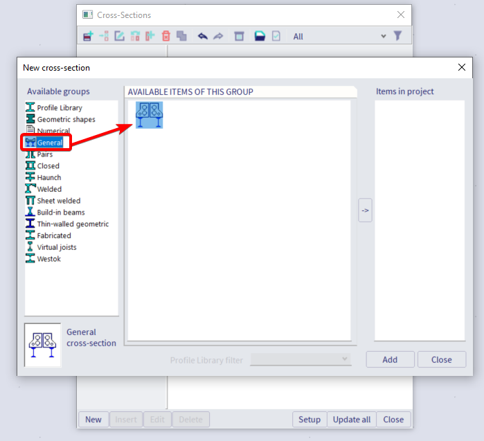
In the cross-section library, it is possible to choose the group ‘General’. Then the cross-section editor will open. In this editor, the option ‘Import DXF / DWG’ is available.
With a centerline
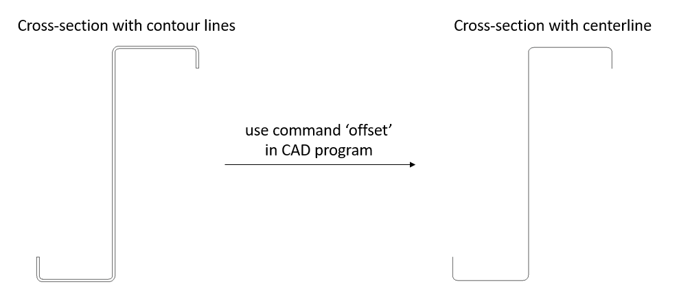
When importing a thin walled section, it is very important to work with the centerline of the profile. It is preferred to create this centerline in the DXF / DWG file before importing the cross-section in SCIA Engineer. This can be done easily by creating an offset in a CAD program.
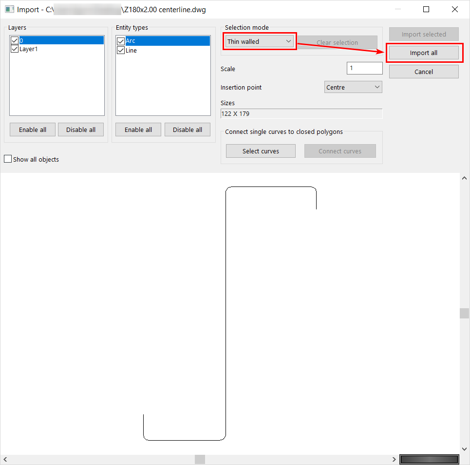
After selecting the import file, the selection mode should be set to ‘Thin walled’, followed by clicking on ‘Import all’.
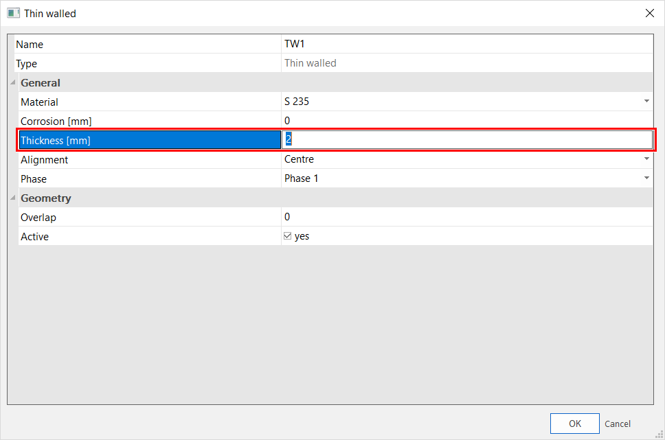
Now the thickness of the cross-section should be chosen.
After confirming, an insertion point should be defined (for example 0;0).
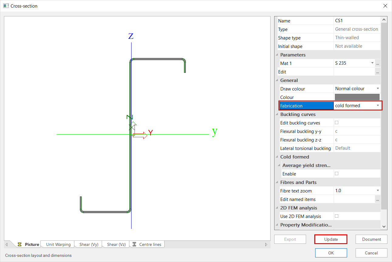
After closing the cross-section editor, the cross-section is shown. It is important to check the fabrication (for example cold formed, rolled, …). After clicking on ‘Update’, SCIA Engineer calculated automatically the cross-section properties.
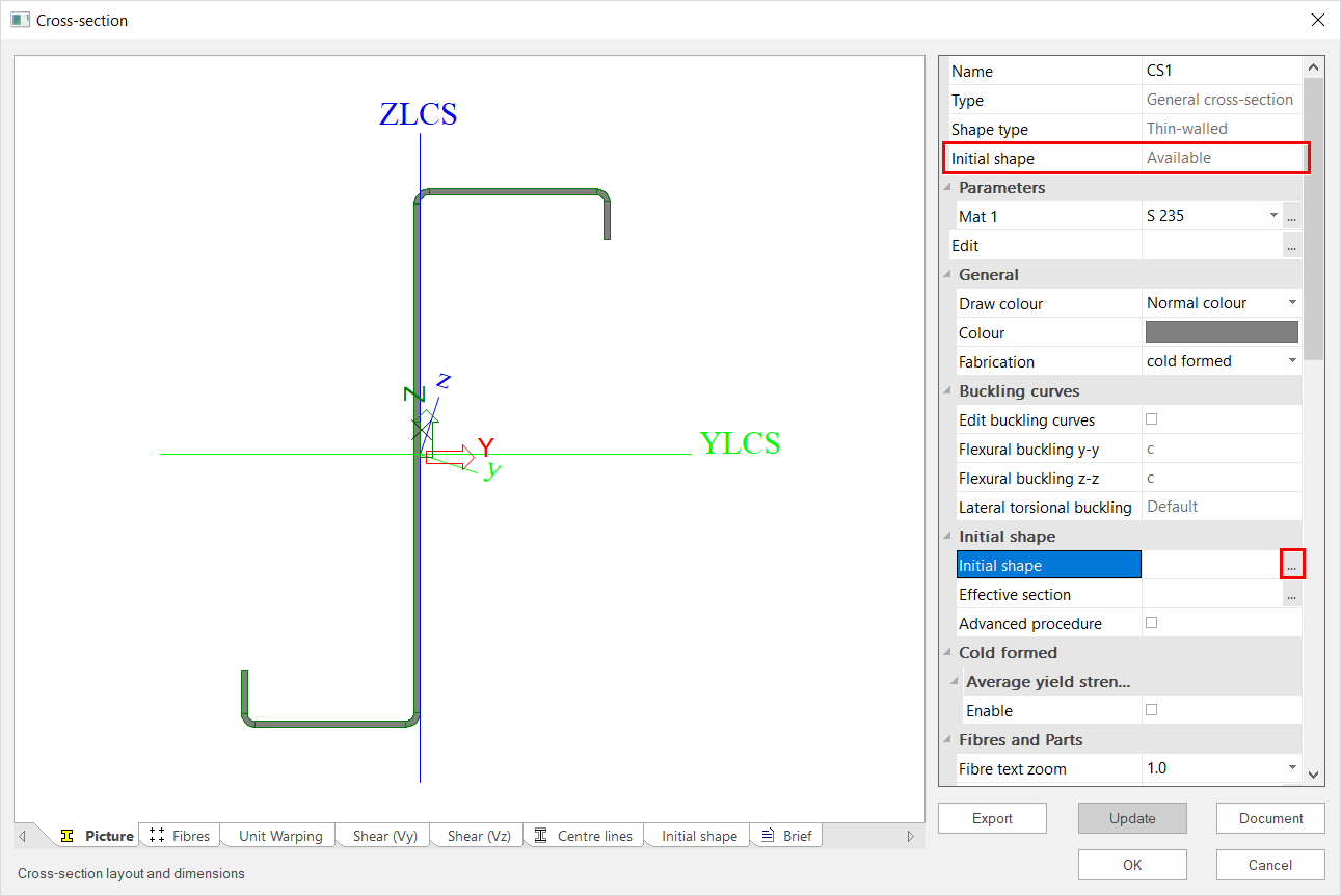
Now there should be an initial shape available. It is advised to verify the parts of the initial shape, because the initial shape is used for the calculation of the effective cross-section properties as well as for determining the classification of the cross-section.
Remark: As alternative it is also possible to work with the option ‘Thin walled’ in the cross-section editor. Then the cross-section can be drawn manually instead of importing it based on the centerline.
With a polygon and a thin walled representation
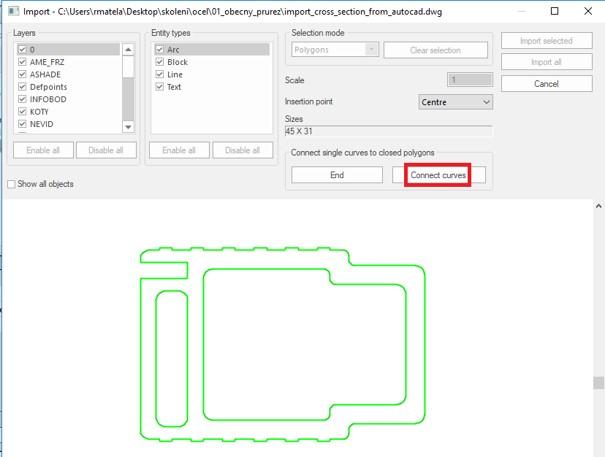
When you want to import more irregular shapes, you can define those with polygons and polygonal openings. To do this you can import your dwg file with contour lines instead of the center line. Import your file into the general editor and follow the steps below.
- It is necessary to create a polygon from the loaded cross-sectional drawing because cross-section breaks into curves. Use the functions 'connect single curves to closed polygons' and the 'select curves' button and use the left mouse button to select all curves from which to create polygons.
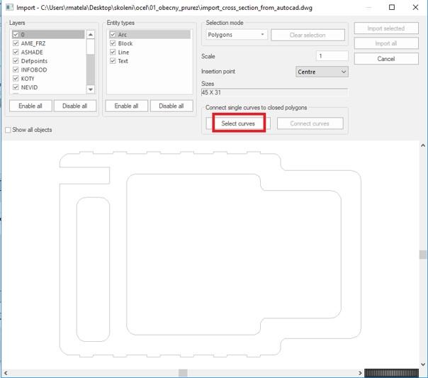
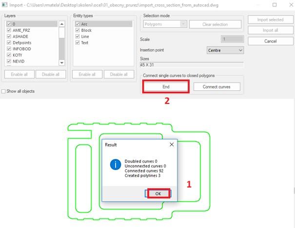
- After selecting the curves, use the command 'connect curves' to create polygons. If this step does not create a polygon of all the different shapes, you should check the original dwg file for small inaccuracies.
- The program will display a report about the created polygons and any errors. Close the connecting curves function with the button 'end'.
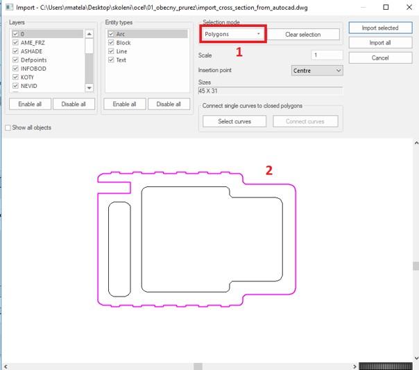
- Select mode: polygons. Use the left mouse button to mark the outer polygon
- Select mode: Polygonal openings. Use the left mouse button to mark the polygonal openings
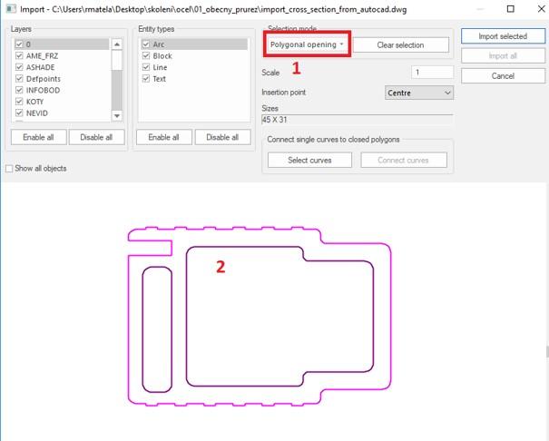
- Import the selected cross-section via the 'import selected' button
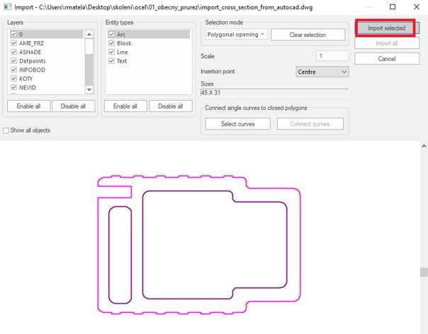
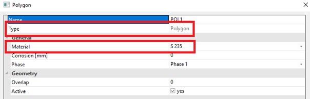
- Select the cross-section material
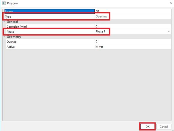
- Select the phase at which the hole is formed
- Select the insertion point in the cross-section editor
Tip: Take care to define all outlines as polylines in the source file and to define each circle segment as an arc through 3 point
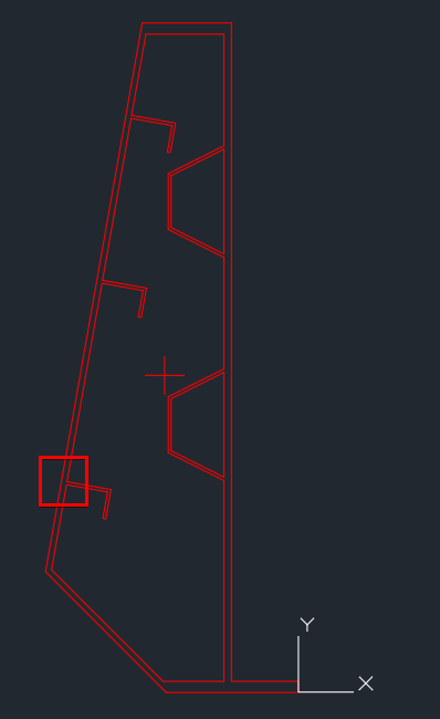
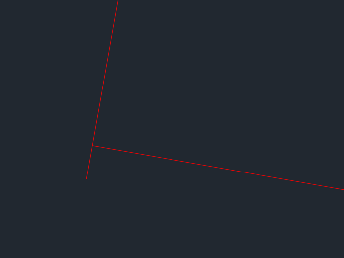
Tip: issues in selecting the curves are often caused by mistakes in the shape of the section. In the example below the shape looks ok, but when zooming in on one of the stiffeners a mistake is noticed.
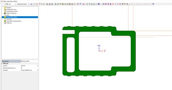
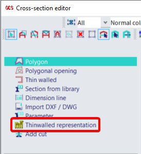
- To allow for automatic classification a thin walled representation should be defined. With this functionality you can overdraw the gross shape using a thin walled representation. The thin-walled representation represents a simplification of the real shape which will be used exclusively for the definition of the initial shape so to allow automatic classification. The exact characteristics of the section will be instead computed on the precise cross-section imported as polygons.
- After clicking on 'close', the following result is obtained
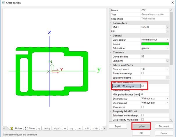
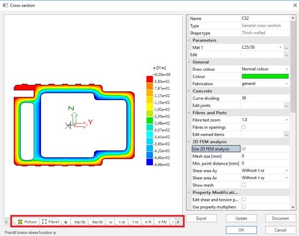
- Click in this window on 'Update' to show the properties of the cross-section, calculated by SCIA Engineer based on standard formulas known from basic mechanics.
To retrieve more correct results for the shear and torsion properties, it’s recommended to select the option ‘FEM analysis’. In that case some calculations are done based respectively on the theories of Grasshof-Zuravski and Prandtl or a Full FEM method can be chosen as calculation type.
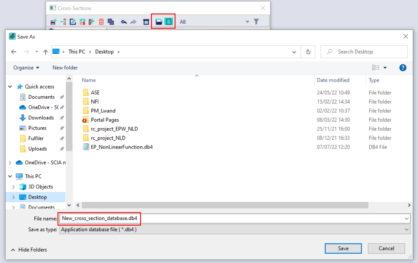
Tip: This new cross-section - possibly together with a whole set of cross-sections - can also be saved to a database file (*.db4) via the ‘Save to file’ icon. Afterwards it can be loaded to any SCIA Engineer project, by means of the ‘Read from file’ icon
Note: some issues has been signaled while working with DXF/DWG file created with the most recent versions of Autocad. In case of similar issue, it is advised to save the DXF/DWG file as '2010' version.