Highlights
- Section and member design of aluminium products according to the latest EN 1999-1-1.
- Classification and effective section derivation for any aluminium cross-section shape: whether taken from internal libraries, drawn by you, or imported from CAD software.
- Effective section derivation for local buckling effects and heat-affected zones from both longitudinal and transverse welds on the member.
- Clear and comprehensive reporting with different levels of detail: from a brief summary to a detailed calculation report with formulas and references to applied articles from the code.
Benefits
Proper and precise handling of aluminium members in SCIA Engineer is achieved by:
- considering all local buckling effects as well as heat-affected zones in effective section calculations and further design verifications;
- at a span level, determination of buckling factors and second-order effects for global member stability;
- fast checking of aluminium structures due to optimised design routines and parallel processing;
- support for a wide number of National Annexes to Eurocode 9: Belgium, Cypress, Czechia, Denmark, Finland, Germany, Greece, Ireland, Italy, Luxembourg, the Netherlands, Norway, Slovakia, Sweden, United Kingdom.
- compatibility of this design functionality with advanced analysis features, such as various types of nonlinearity, absences, 2D FEM stress analysis of cross-sections, etc.
Cross-section analysis
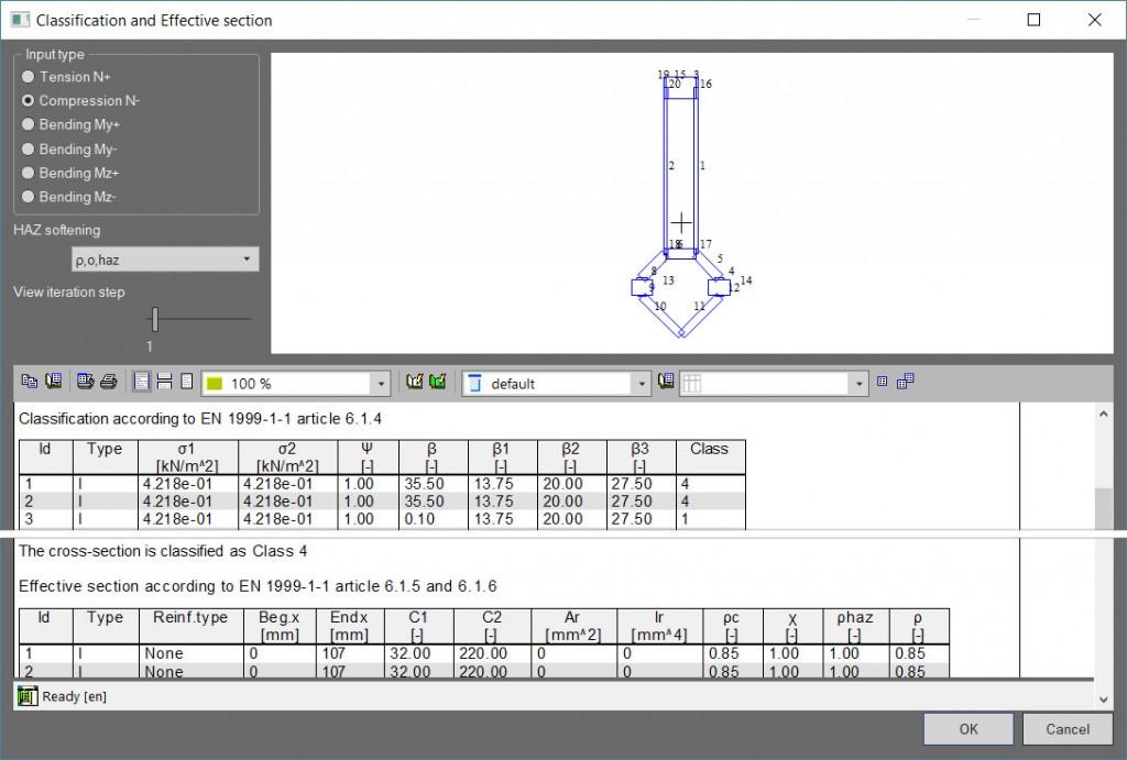
SCIA Engineer has unique, versatile routines for analysis of thin-walled sections: section classification and derivation of effective sections are the essential step before applying the checking rules of the code.
- On top of what is available for steel design, the aluminium cross-section tools also take into account the presence of welds.
- The Profile Library contains a wide variety of shapes you can adapt, store and use according to their needs.
- By using the General Cross-section Editor (included in module sen.05), you can create any cross-section shape and use it in the analysis and structural design; the shape can be drawn by the integrated drawing tools or even imported from dxf and dwg files.
- SCIA Engineer automatically assigns wall types (internal, fixed, symmetrical or asymmetrical outstands) to individual parts of all known cross-section shapes, even when these are combined (welded or bolted) together.
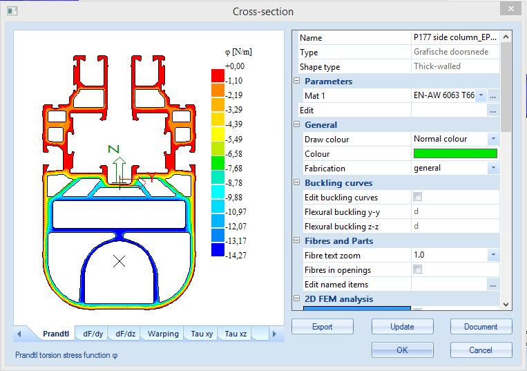
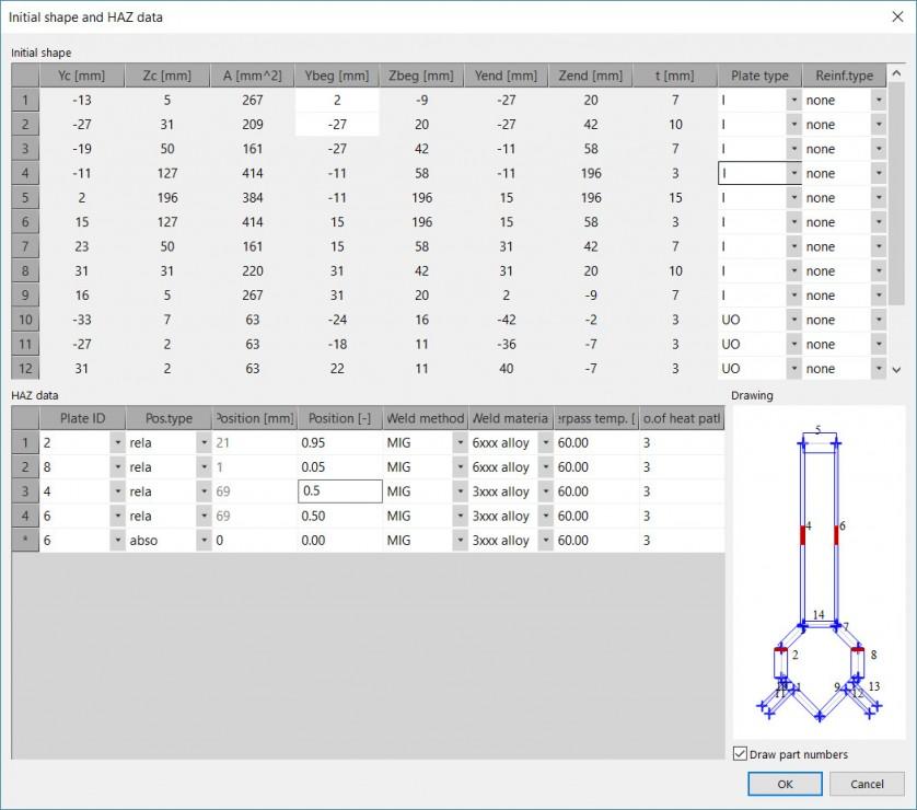
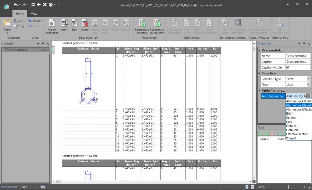
- Reduced cross-section properties are calculated for compression, strong- and weak-axis bending, taking into account local and distortional buckling and the effect of HAZ.
- The obtained effective sections can he displayed graphically, and all iterations of the calculation are reported in tables.
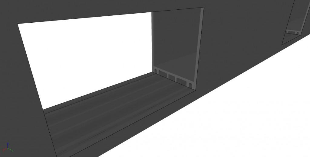
Handling of complex shapes
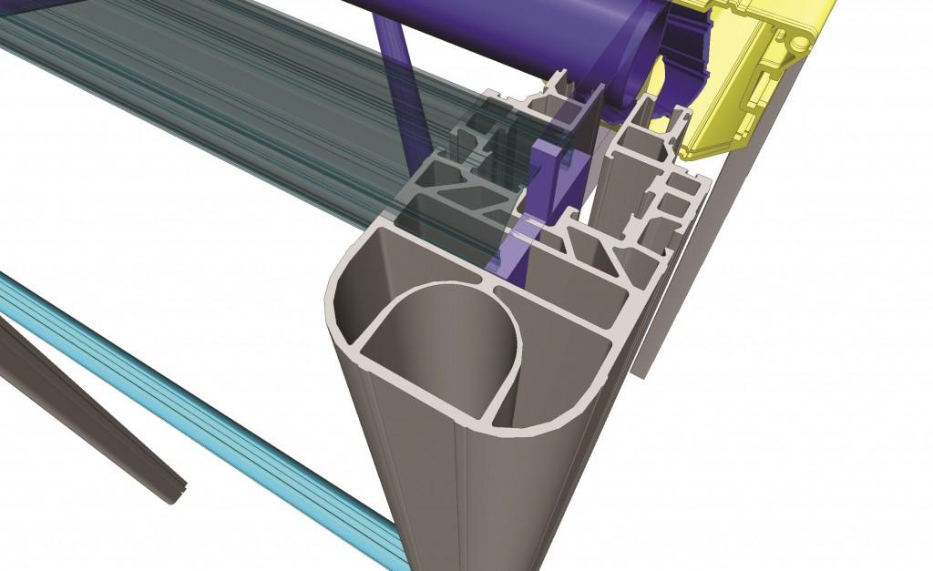
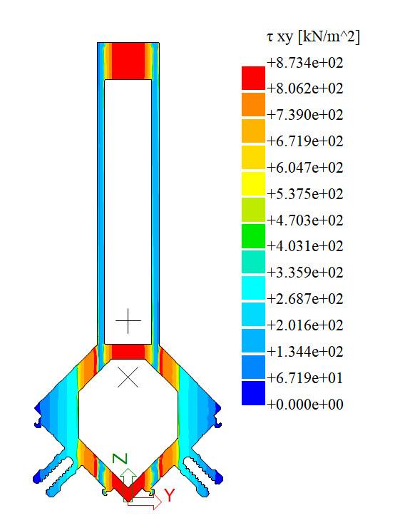
Eurocode 9 requires that sections be classified according to their wall slenderness; plastic or elastic verifications are then performed based on this, and even reductions for local buckling effects need to be considered. This makes it necessary for aluminium cross-sections to be represented by walls with a thickness. This is difficult when the shapes are complex, like the ones normally used in facades.
The good news is that SCIA Engineer has a solution for this. A thin-walled representation can easily be sketched to overlay any cross-section shape. It means that the design will benefit from "the best of both worlds:" FEM analysis can be performed with the real cross-section shapes (to derive deformations, internal forces and stresses), and in the EC9 design module, classification and effective section calculation can be performed and the results used in code specified checks.
Heat-affected zones
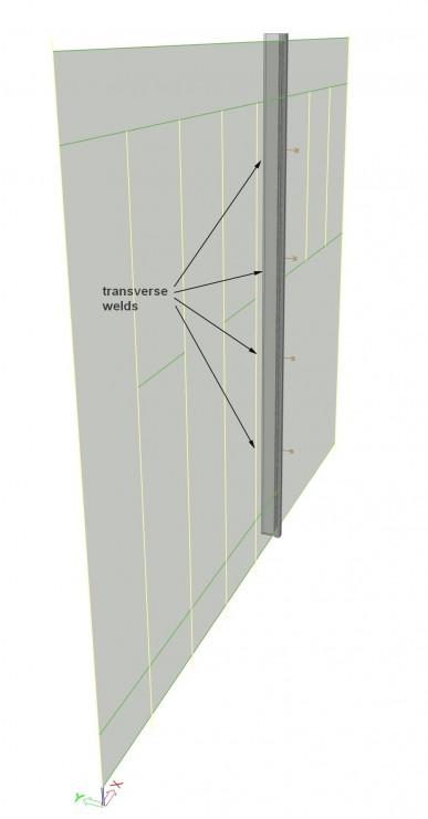
When aluminium members are welded, local stability effects may be intensified due to softening of the material. Eurocode 9 puts special attention to a correct handling of welds at the level of design.
In SCIA Engineer, you can input both longitudinal and transverse welds onto the members. Welds will augment the used effective section properties in their heat-affected zone (HAZ). Transverse welds will result in a completely new effective section along the extent of the HAZ.
Checks
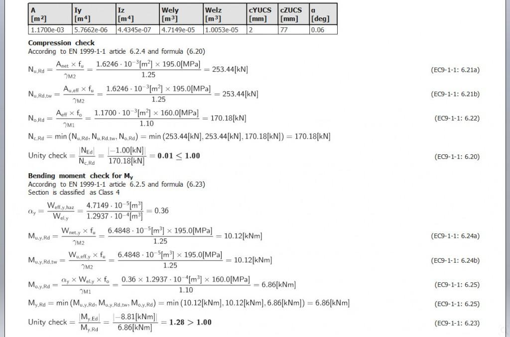
- Section checks are performed for axial forces, bending moments, shear forces, torsion, warping, and combination of these load effects (N + My,z + Vy,z, Vy,z + T).
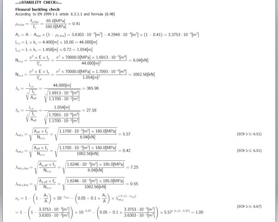
- Stability checks are performed for flexural buckling, torsional and torsional-flexural buckling, lateral torsional buckling, shear buckling for I-sections (symmetrical or asymmetrical), combined bending and axial compression.
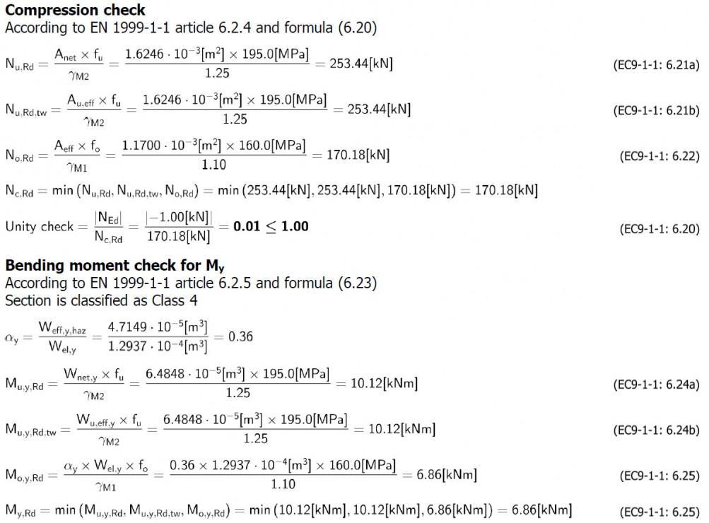
- Checks are performed according to the latest EN 1999-1-1:2007 + A1:2010 + A2:2013 with special considerations for transverse welds.
- An automatic design (AutoDesign) functionality makes it possible to optimize the dimensions of library or parametric cross-sections in order to obtain optimal utilisation.
- Arbitrary cross-sections (with haunches, variable height) and members with holes can also be designed.
- The program also allows for the "most dangerous" load combination keys to be extracted and used further for e.g. stability or second-order analysis. The term “most dangerous” here refers to load combinations that result in the highest section or stability utilisation ratio.
Reporting
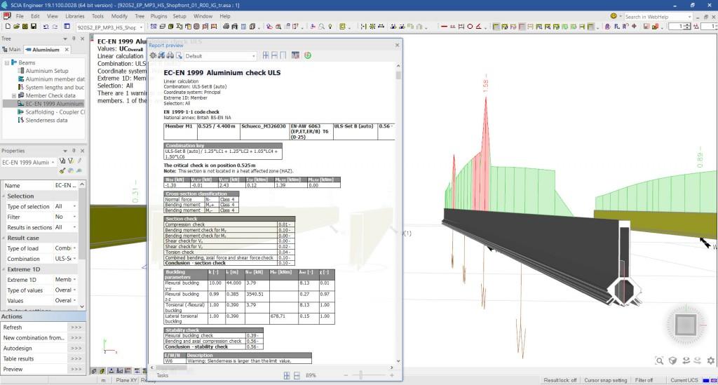
The Aluminium design module benefits from an interactive reporting interface, where the results of the design are easily accessible in various forms:
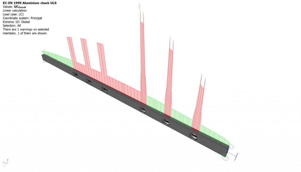
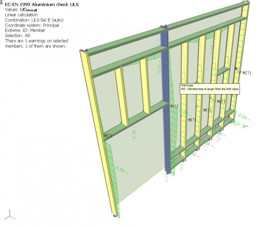
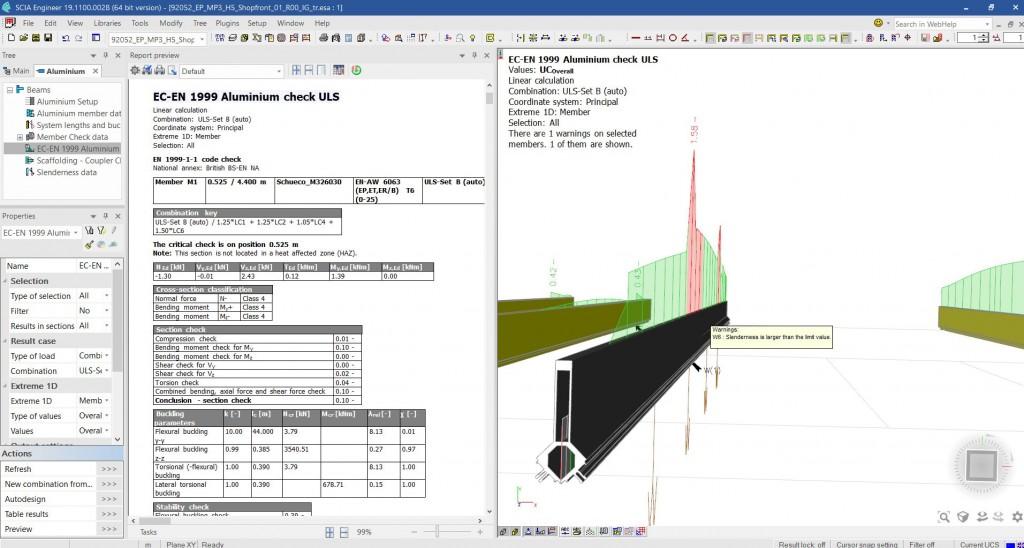
- colour-coding utilisation ratio diagrams in the 3D scene helps quickly identify problems anywhere in the structure;
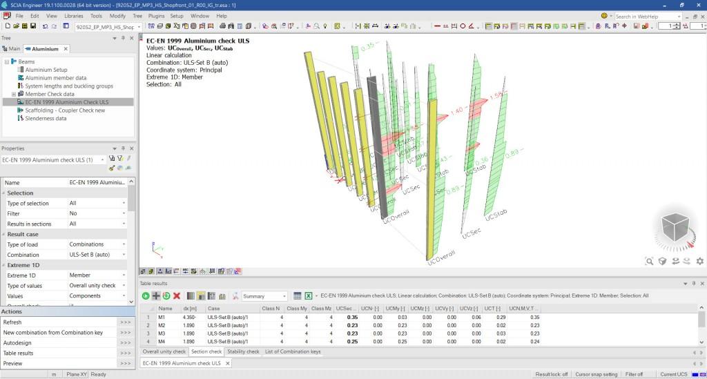
- the design output document is easily printable in table form via the Brief report or via Table Results;
- A Summary report per member summarises all important parameters of the design and all checks on a single page;
- A Detailed report shows all calculations as formulas (or tables, if preferred) with references to the applied articles from the code, allowing you to follow and verify the logic and individual steps of the design;
- The Summary and Detailed report are directly accessible by double clicking on the rows in Table Results. In this way, you quickly get the connection between details of the calculation and the members visualised on the screen.
- Errors, warnings and notes can be shown interactively by hovering over specific members in the 3D scene.
- A detailed overview of the section classification and effective section derivations can be added to the Engineering Report as well.
- The selected settings (e.g., selected load combination, member names, type of calculation and extremes) are displayed in the Result Legend in the top left corner;
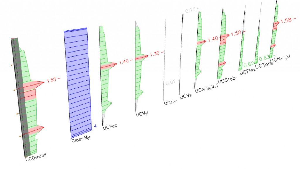
- Besides the overall utilisation ratio, you can plot specific checks on members using the Result Components.
Required modules:
- sen.00

Want to try SCIA Engineer yourself?
Explore how our software and services can help you optimise your work and boost your productivity. Try it for yourself with a free 30-day software trial.
Download a free 30-days full trial