Highlights
- Capture the lateral-torsional buckling response of steel profiles by numerical simulation with 7 DoF (Degrees of Freedom) beam elements.
- A 7 DoF solver lets you determine Mcr via the eigenvalue analysis or perform a full nonlinear analysis where second-order effects also cover torsional deformation and distortion.
- Full nonlinear analysis eliminates the need to do stability checks in the Steel Design module.
The sensd.07 module sets up a bidirectional link with the Frilo BTII solver, where FEM calculations are performed using elements with 7 degrees of freedom per node. This type of element formulation correctly captures warping in the member and any lateral-torsional buckling (LTB) that may occur.
The member of interest is exported and analysed, taking into account the boundary conditions and loads applied in SCIA Engineer. Various three-dimensional loading scenarios can be simulated, and results may be used for verifications in the ultimate and serviceability limit states, including fire resistance.
The functionality can be used in two different ways:
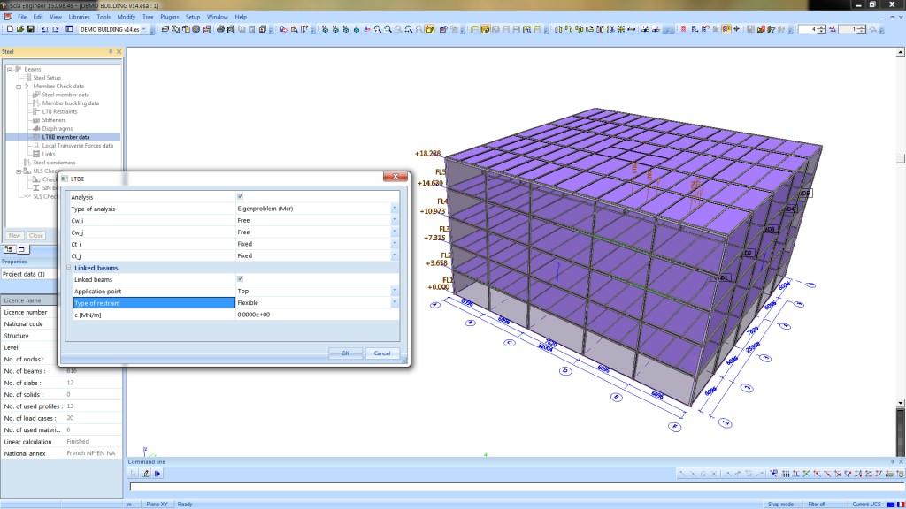
- to accurately determine the critical buckling moment Mcr via an Eigenvalue stability analysis: important when the beams have unusual cross-sections or loads;
- to perform a 2nd order analysis aimed at establishing lateral and torsional instabilities; in this case, stability checks for LTB do not have to be performed in the design phase.
How it works?
Hot-rolled or cold-formed elements may be analysed, with both open (e.g., an I- or U-section) or closed (e.g., a RHS) cross-sections. A single beam element is taken out of the structure and is analysed as an isolated beam, with:
- the proper boundary conditions (including the ones related to torsion and warping);
- the forces at the beam ends (calculated in SCIA Engineer);
- all loads applied on the beam;
- intermediate restraints (diaphragms, LTB restraints, linked beams);
- initial imperfections (used only in the case of 2nd order analysis).
In both types of application (i.e. critical buckling moment as well as in the 2nd order analysis), Frilo BTII sends the results to SCIA Engineer, where they can be displayed and/or added to the Engineering Report.
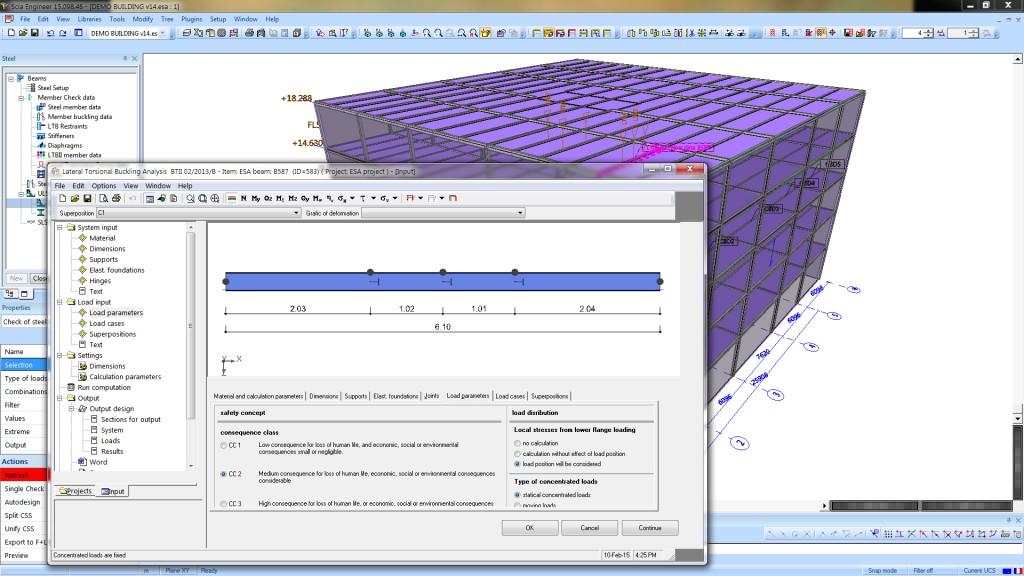
Loads
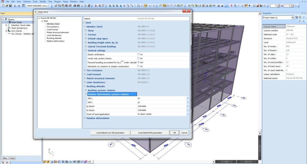
The software distinguishes between loads applied in the centroid of a section and loads applied in the shear centre. Loads not applied in the shear centre of a section are supplemented by additional torsional moments (automatically determined).
Various load types may be applied on the analysed member: point and distributed forces and moments, as well as any combination of these. The self-weight is converted to an equivalent line load on the beam. Moving loads may also be defined to design e.g. crane runways.
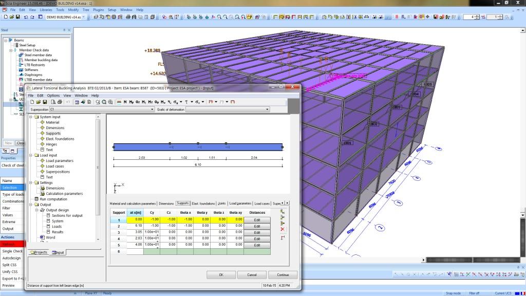
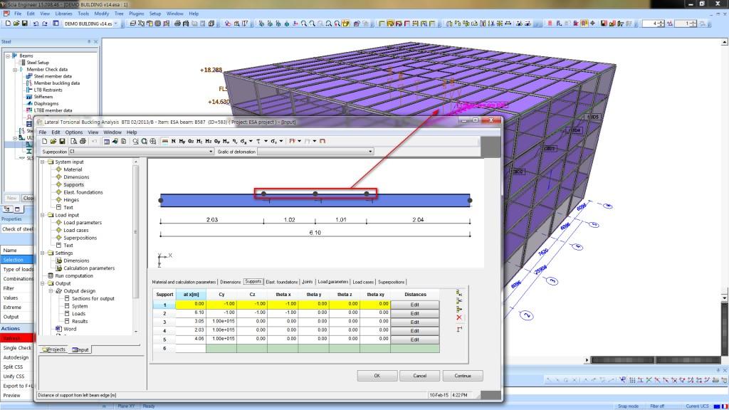
Intermediate supports
The module analyses 3-dimensionally-loaded beams with any boundary conditions. The following intermediate restraints are considered:
- Discrete intermediate supports along the analysed beam: these may be situated and oriented freely in the 3D environment, are characterised by a user-defined distance from the shear centre of the section, and may be rigid or flexible (spring stiffness is defined by the user).
- Continuous supports (these act as an elastic foundation): these may be freely oriented and you may specify their stiffness and distance to the shear centre.
- The Steel Design module does not take into account LTB (or other) restraints when these are located on the tension side of a member. The esasd.07 module does take such restraints into account during the design verifications. Although the effect of constraints on the tension side is limited and more modest in comparison to restraints on the compression side, but taking these into account leads to a more economical design.
Intermediate lateral restraints are defined via the SCIA Engineer entities: LTB restraints, diaphragms and linked beams.
- LTB restraints are transformed to elastic springs in Frilo BTII.
- Diaphragms are transformed to elastic foundations (linear springs and rotations springs).
- Beams that are connected to the analysed one are transformed to supports with elastic restraint.
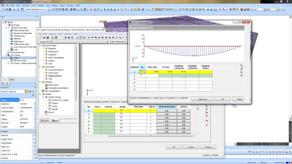
Imperfections
Initial imperfections are taken into account during the 2nd order analysis of the beam stability.
- Bow imperfections in the direction of weak-axis bending are always taken into account, as recommended in EN 1993-1-1, Article 5.3.4 (3). The standard says that, during a 2nd order calculation which takes into account LTB, only these imperfections need to be considered.
- Eccentricity in the direction of strong-axis bending may also be taken into account, if desired.
- For verifications according to the DIN, ONORM, EC-EN, and EAE standards, the size of the initial imperfections may be calculated according to the design code.
Mcr eigenvalue calculation
- This application of the module calculates the bifurcation load corresponding to the LTB eigenmode.
- Then, this critical moment value is sent back to SCIA Engineer, where reduction factors for stability are determined using the equivalent bar method.
- The method can be used with the following national codes: EN 1993-1, ENV 1993-1, SIA 263, DIN 18800, ÖNORM B 4300, NEN 6770/6771, IS 800, EAE 2004.
2nd order calculation of torsion and warping
The module lets you perform the 2nd order analysis in the ultimate and serviceability limit states for beam members with any type of supports and loading.
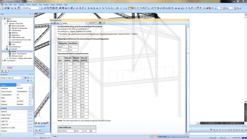
- Internal forces, elastic deformation, normal and shear stresses are calculated with consideration of warping deformations. An additional 7th degree of freedom represents the value of warping in the cross-section.
- Boundary conditions are defined separately for torsion and warping; in this way, a member may be fixed at either end against torsion, while warping remains unrestrained.
- By using results from 2nd order calculation that captures LTB, many code-prescribed checks may be skipped. As a result, only stresses need to be checked (similarly to the general method described in EN 1993-1-1).
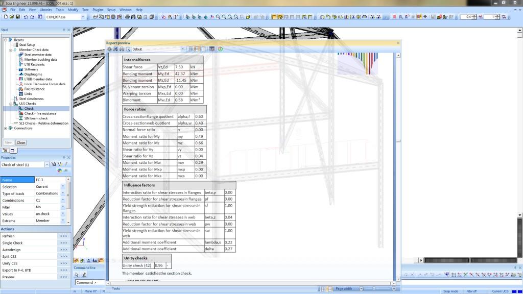
- The calculated torsional and warping moments (St. Venant torsion, warping torsion and bimoment) are then used in a stress check in SCIA Engineer.
- The stress check takes into account the normal force in the beam member (calculated in SCIA Engineer) and the maximum values of shear forces and bending moments (obtained either from the calculation in SCIA Engineer or from the Frilo BTII solver).
- When torsion is present in the member, it is strongly recommended to perform the 2nd order analysis instead of the eigenvalue calculation.
- The method can be used with the following national codes: EN 1993-1, ENV 1993-1, SIA 263, DIN 18800, ÖNORM B 4300, NEN 6770/6771, EAE 2004.
Limitations
- Only linearly elastic material response is supported;
- The modulus of elasticity and the shear modulus should be constant along the entire beam.
- The analysed beams should be straight.
- The numerical analysis in the BTII solver ignores normal forces acting along the beam axis. These are however taken into account in the final checks performed in SCIA Engineer
Export to Frilo BTII
If the standalone Frilo BTII application has been installed, it is possible to directly export a beam from SCIA Engineer to it via the 'Export to BTII' action button. All relevant properties and additional data are exported as well.
There are a few more features available in the standalone BTII, e.g.:
- For open sections, additional considerations are taken into account for secondary flange bending due to eccentric loading on the lower flange. The additional stress generated by secondary flange bending is considered during the final stress verification.
- Various moving loads can be defined in the standalone application. These can be used in the verification of different types of crane beams.
Required modules:
- sen.00

Want to try SCIA Engineer yourself?
Explore how our software and services can help you optimise your work and boost your productivity. Try it for yourself with a free 30-day software trial.
Download a free 30-days full trial