Highlights
- Multi-parametric interaction between ground slab and foundation soil
- Taken into account: distribution and intensity of load, contact stress between structure and soil, footing surface geometry, local geological conditions
- Input of subsoil using data from borehole surveying
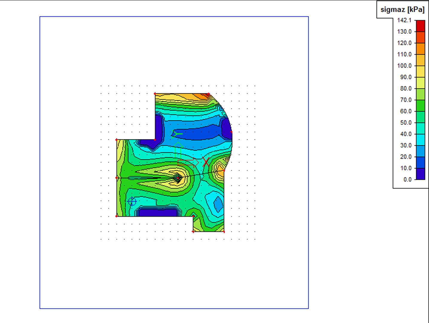
- Display of SigmaZ and soil structure strength
- Generation of vertexes (soil points)
- Using soil interaction together with seismic analysis
Determination of the ‘real’ C parameters and calculation of the interaction between the structure and the soil due to settings of the soil. The distribution of the tension in the soil under the foundation plates, the distribution and the level of the load, the contact tension between the structure and the subsoil, the geometry of the contact layer and the geological characteristics of the subsoil at a specific position. As the C parameters have an influence on the contact tension (and vice versa), the subsidence of the contact layer and a consequence also the C parameters are influenced by the contact tension; the calculation of the properties is iterative. The calculation determines the occurring settings and the influence of these settings on the structure. The calculation is based on the Pasternak model.
- The module calculates C parameters for the interaction between ground slab and foundation soil, taking into account loading distribution and intensity, structure/soil border contact stress, footing surface geometry and local geological conditions.
- The model used in “Soil-in” is called the Energy or More-constants Model and has been used in practice since 1975, comparing well with many in-situ measurement systems. The “More-constants model” name refers to the energy model capacity:
- the shear stiffness of the subsoil C2 using the Pasternak model;
- the orthotropy or anisotropy of the subsoil by means of the C2x, C2y and C2xy constants;
- the surface friction in the structure/soil interface by means of the C1x, C1y constants.
- The “Soil-in” module uses a layered half-space model with these features:
- You can apply the Boussinesq influence function to calculate the development of the vertical stress component SigmaZ in the subsoil in any surface overload situation despite any layering, uneven soil constitution or other anomaly. The various geomechanical standards approve this method.
- You can determine any overloading at the excavation surfaces using the Boussinesq formulae for a half-space loaded at a general depth.
- The model uses the approximate solution of an elastic layer of finite thickness to indicate the existence of an incompressible layer.
- The model calculates the soil compression strain components and settlements taking into account the nature of the subsoil layers.
- The program follows the Eurocode 7.
Input
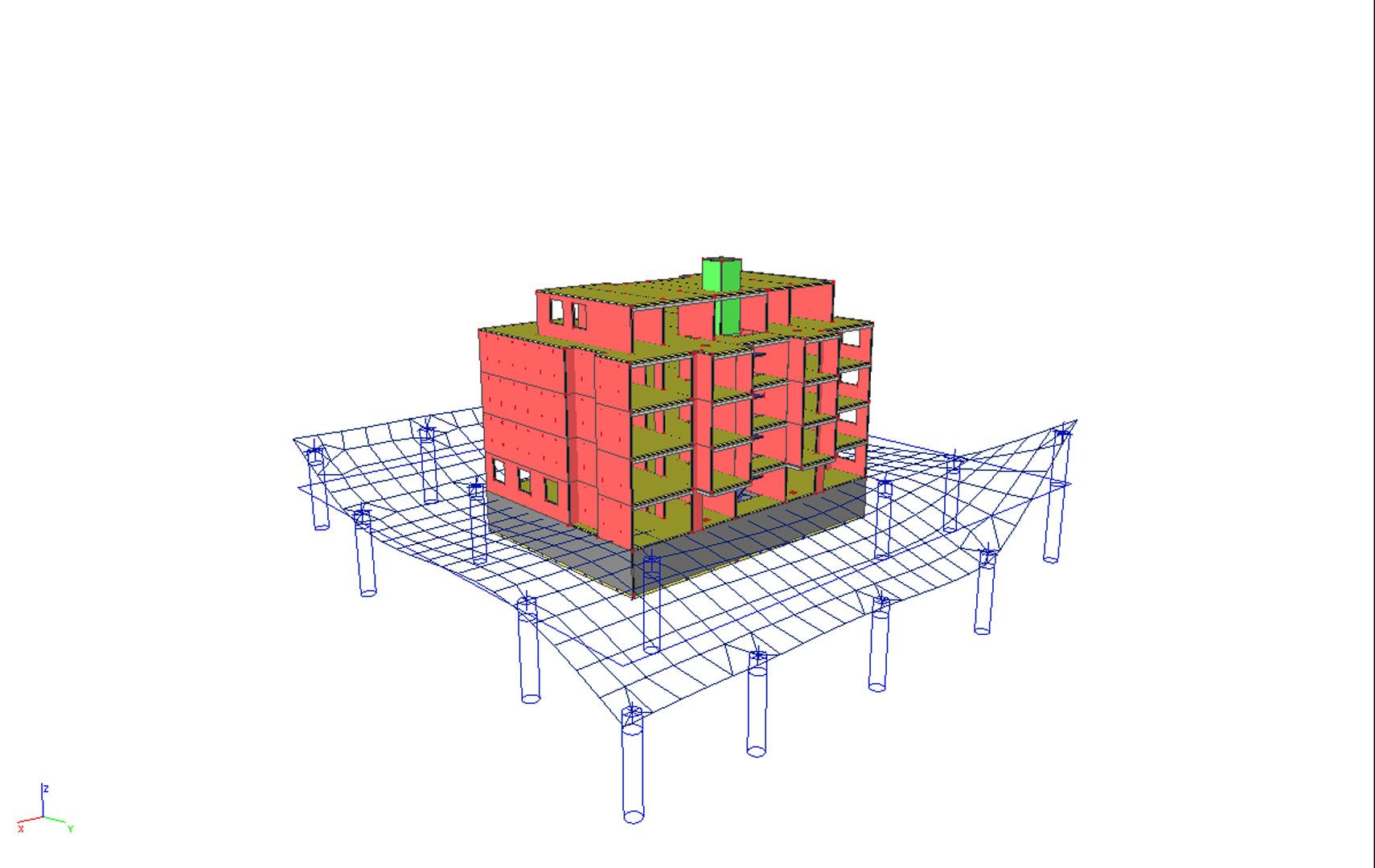
You select foundation plates where the “Soil-in” module should determine stiffness, meaning that you can select only those foundation slabs that should be analysed by “Soil-in”.
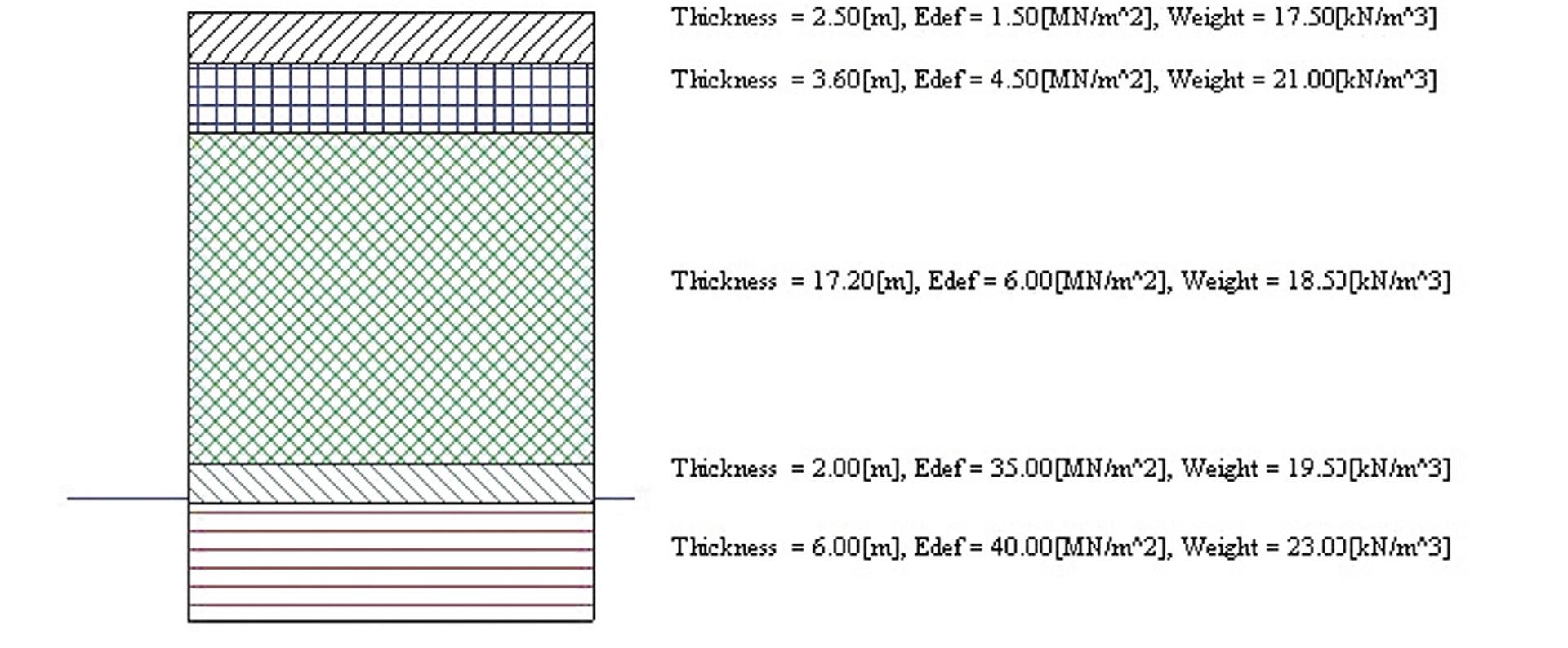
The model can define several boreholes with different layers and properties in each borehole:
- t = thickness of the layer;
- E = deformation modulus of soil mass in compression (cylindrical standard test);
- n = Poisson’s ratio;
- g = specific weight dry and wet;
- m = soil structure strength factor (defined in different codes).
You should consider excavation if the foundation plate and subsoil do not interact on the original terrain surface. The program calculates the parameters automatically.
Calculation
The program needs the structure-soil interaction parameters for subsequent iteration. Firstly, the FEM analysis of the upper structure with initial C interaction parameters (which can be adjusted) gives a first approximation of contact stress.
These subsoil contact stress values serve as input for “Soil-in”. This program solves settlements and corrects C parameter values. The program repeats the whole FEM calculation + “Soil-in” cycle until the iteration test is satisfied, thus obtaining the correct deformation and internal force values.
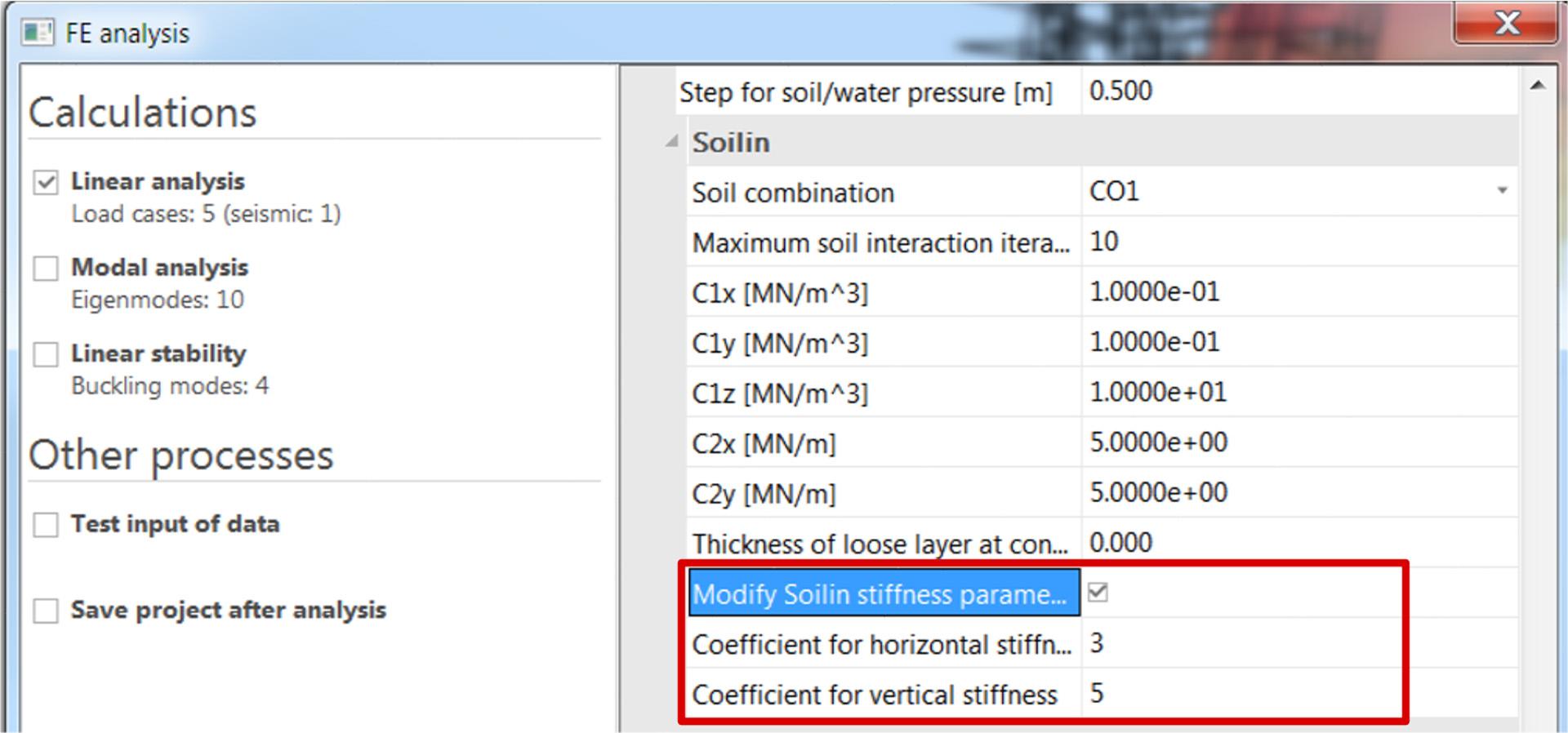
If Soil interaction functionality is enabled and at least one seismic load case is present in the project, the solver setup includes fields that enable using soil stiffness multiplied by custom factor exclusively for analysis of seismic load cases. For ordinary soil conditions the applicable factors vary between values 3 - 10 based on the subsoil type. In the case of other load cases and in the case of other type of analyses (stability, dynamics) the soil behaves as defined in the model without taking into account these custom multiplication factors. See typical settings of solver setup in the figure.
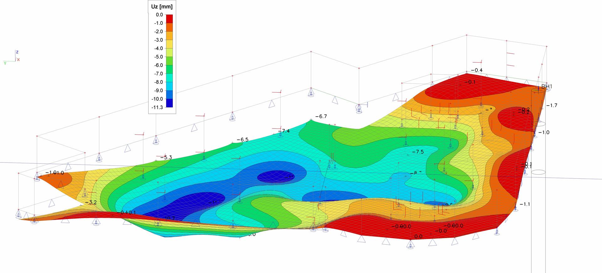
Results
Both graphical and numerical results, along with all standard SCIA Engineer output facilities - iso-bands, isolines, DXF export, search for extremes, and documentation - are available.
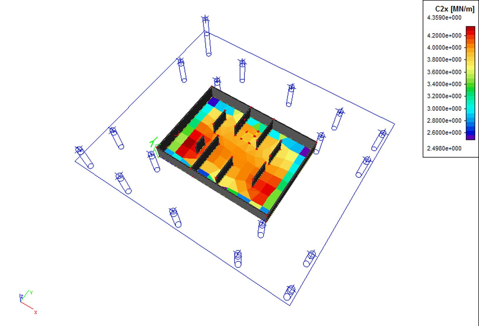
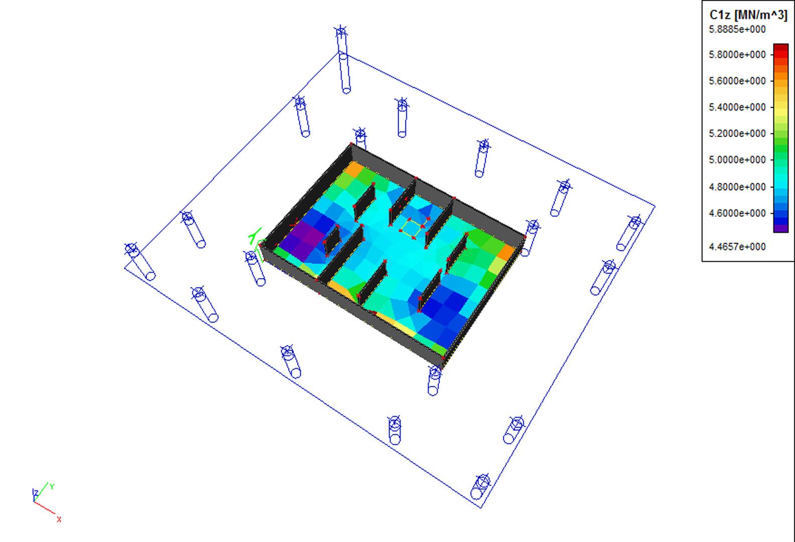
The program determines and displays the C1z, C2x and C2y coefficients. Foundation plate/subsoil contact stress values at every iteration are also available.
Required modules:
- sen.00

Want to try SCIA Engineer yourself?
Explore how our software and services can help you optimise your work and boost your productivity. Try it for yourself with a free 30-day software trial.
Download a free 30-days full trial