Highlights
- The cable can be defined as straight or slack. For slack cables, the initial curved shape is calculated for self-weight of the cable or another user input distributed load
- Initial prestressing can be added to cable properties
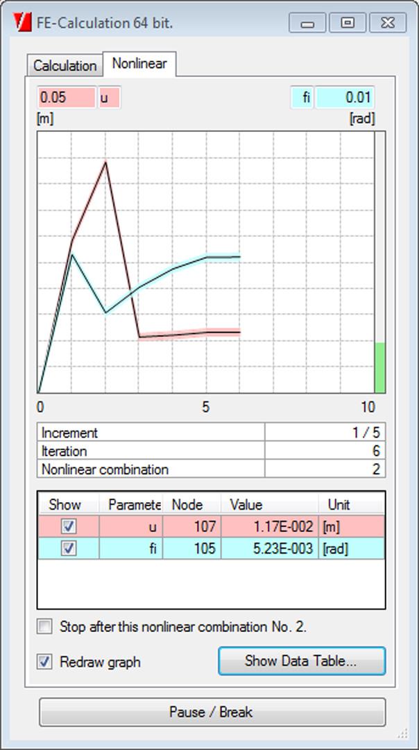
- Geometrical non-linear analysis of cables uses Newton-Raphson method that is suitable for calculation with large displacements
- Calculation of shells as 2D-elements with tensile axial stiffness only.
- Non-linearities such as members, only traction/pressure, non-linear springs etc. are taken into account.
- The results include calculation buckling factors (ratio between the critical buckling load and the applied load).
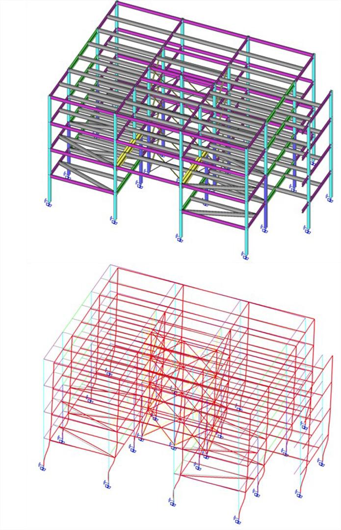
- Deformed shape can be displayed graphically.
- The critical buckling mode can be imported into the geometric non-linear calculation as an initial deformation (in combination with geometrical non-linear module).
This module includes advance functionality for geometric non-linear analysis such as cables, membranes and so-called non-linear stability analysis.
Cables
A cable element is an element with almost no bending stiffness.
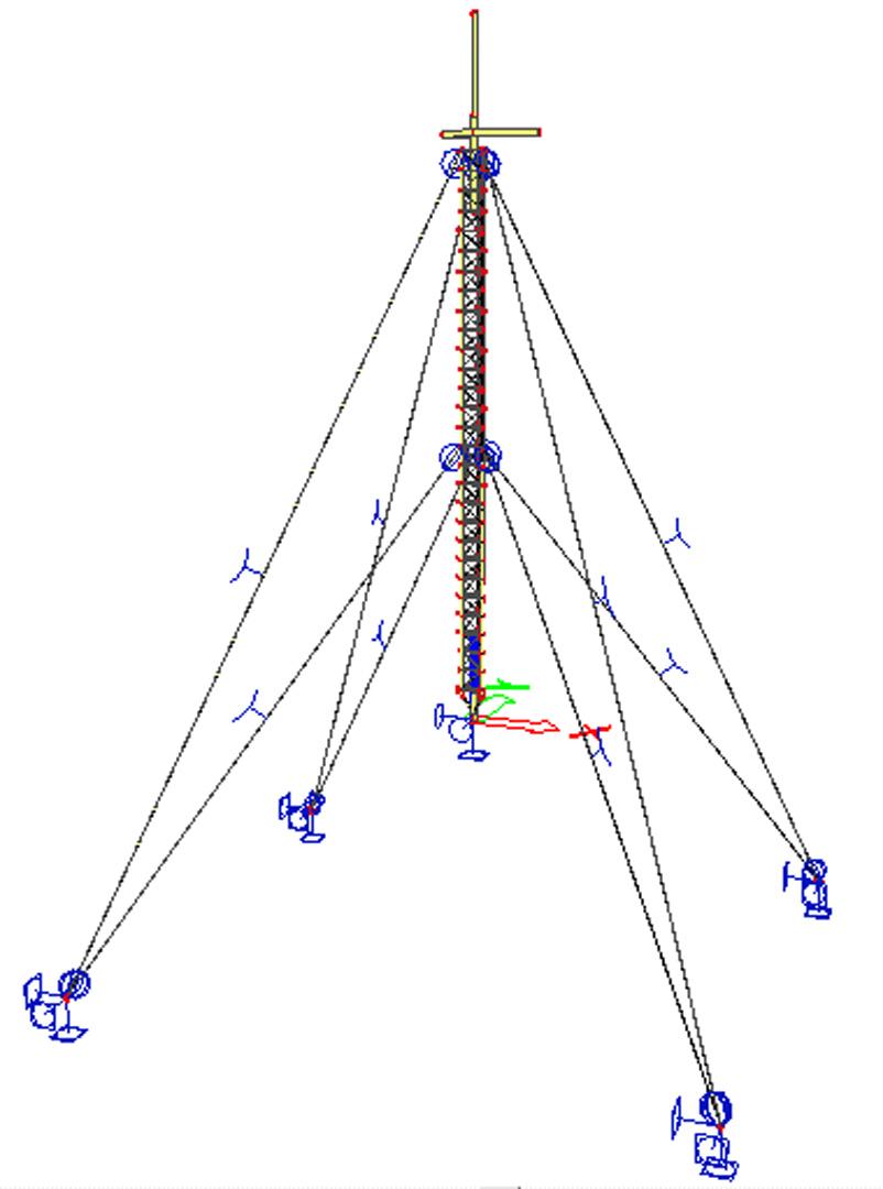
Two cable elements can be modelled:
- straight cable (pre-stressed element)
- slack cable.
Straight cables
Only the pre-stressing force must be input for a straight cable.
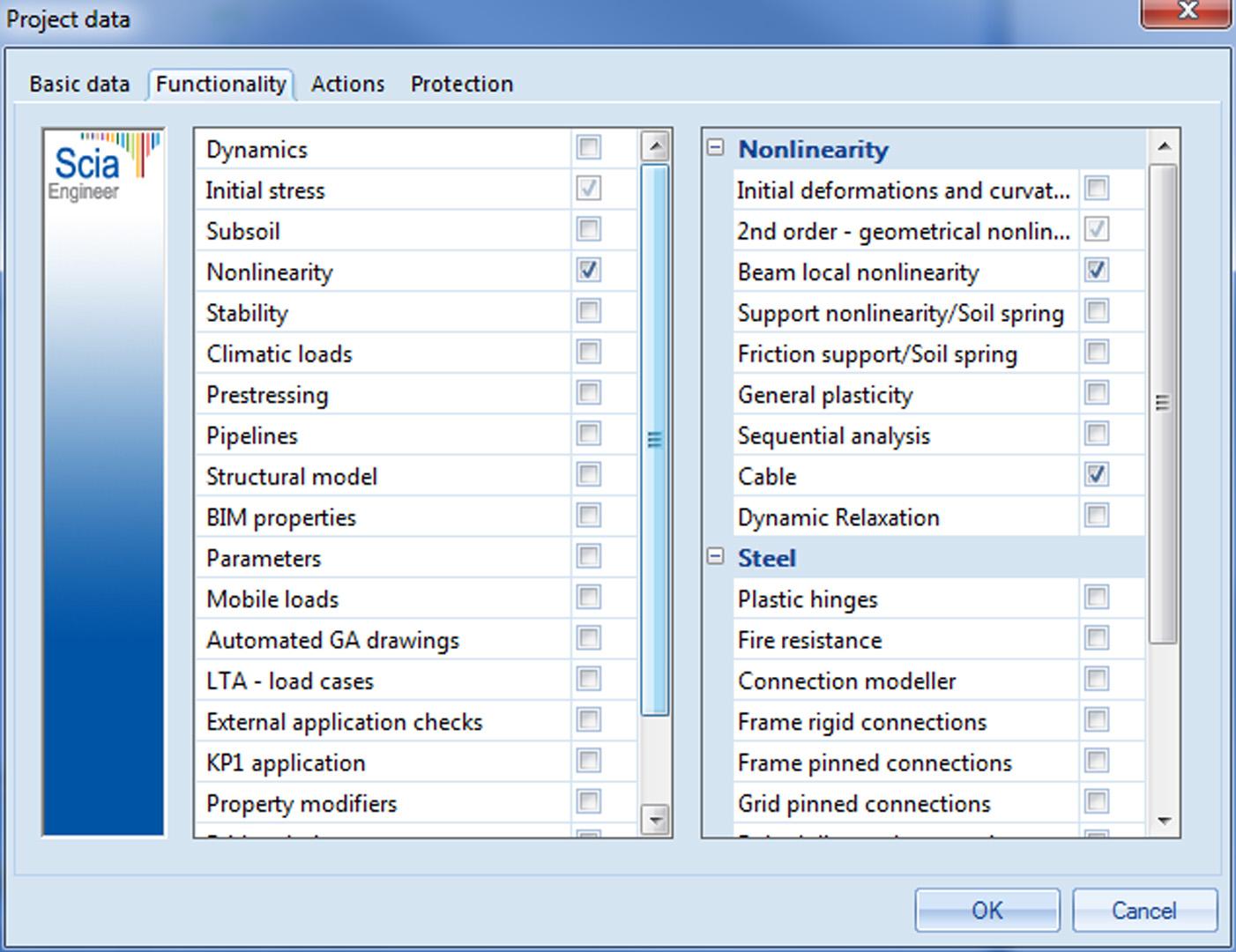
Note: Proper settings must be made in Project Setup dialogue, Functionality tab. Options Initial stress, Nonlinearity, Beam local nonlinearity and 2ndorder calculation must be selected.
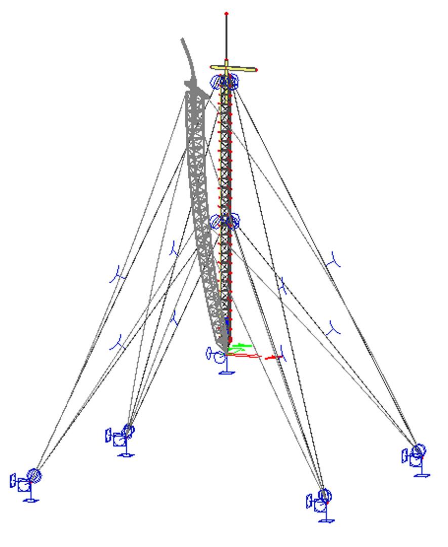
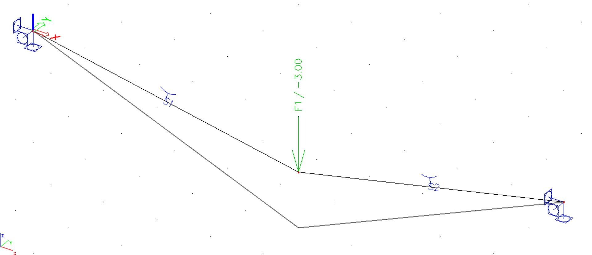
Slack cables
In addition to pre-stressing force, an additional parameter must be defined for a slack cable. The cable is subject to additional load: either (i) self-weight load, or (ii) a general load acting under the given angle and having identical orientation as the local rotation axis fix of the 1D member. These parameters are used to determine the slack of the cable in a particular direction. All calculations are carried out on the "deformed" structure. This means that the final deformation of a cable is calculated from this "slack" shape and not from the ideal straight shape of 1D member.
Note: Proper settings must be made in Project Setup dialogue, Functionality tab. Options Initial stress, Nonlinearity, and 2nd order calculation must be selected. Option Beam local nonlinearity does not have be ON; it would lead to unnecessary increase of the calculation time.
Note: ONLY Newton-Raphson method can be used for this type of analysis. Timoshenko method MUST NOT be applied for the analysis of slack cables.
When inserted into the model, a 1D member with this type of nonlinearity is marked by the dedicated symbol (remember that in order to see the symbol, view parameters must be adjusted to show model data).
Technical background
No special finite element is used for this type of analysis. Regular 1D member element is used, but its flexural stiffness is very, very small. Small shear forces that appear during the iterative calculation are deleted.

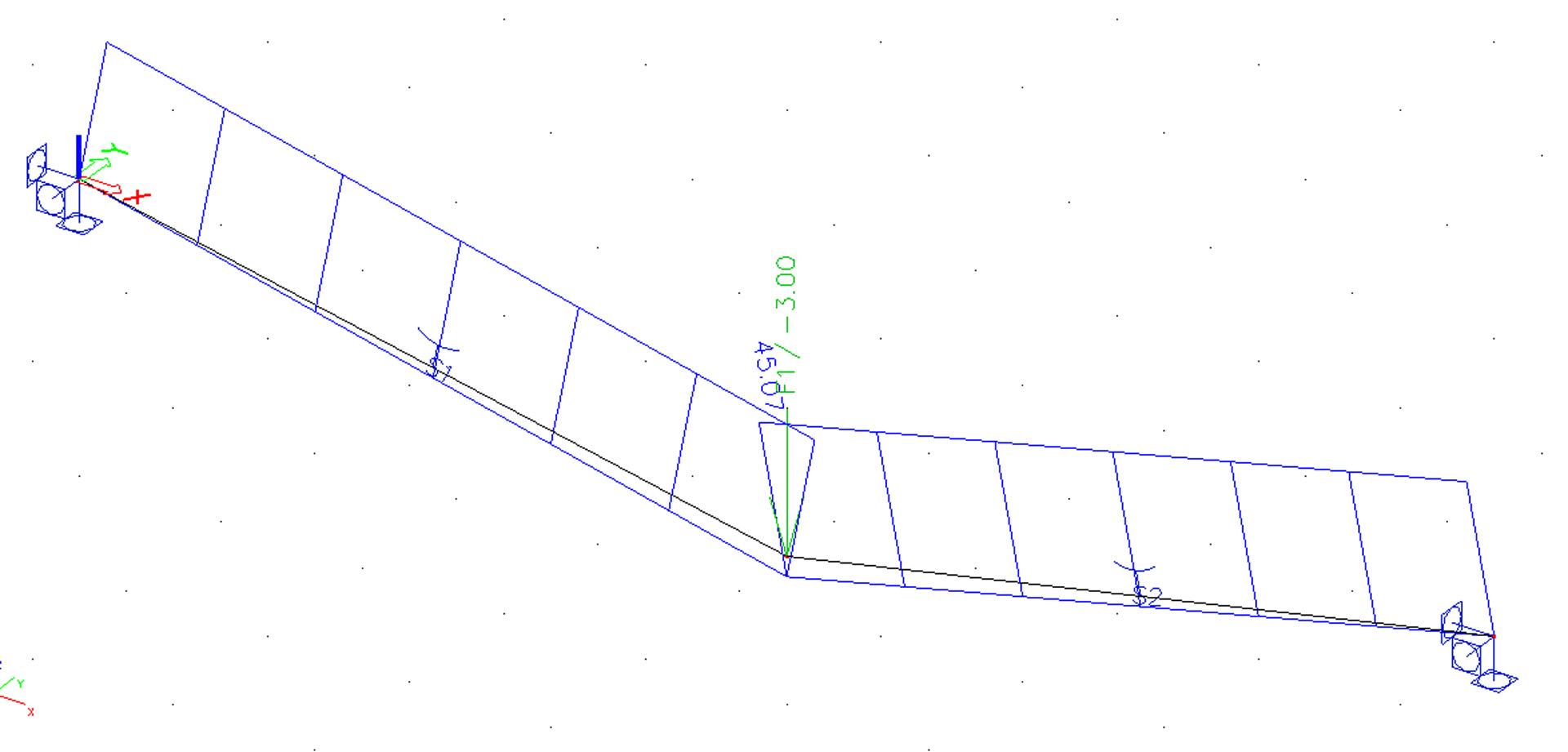
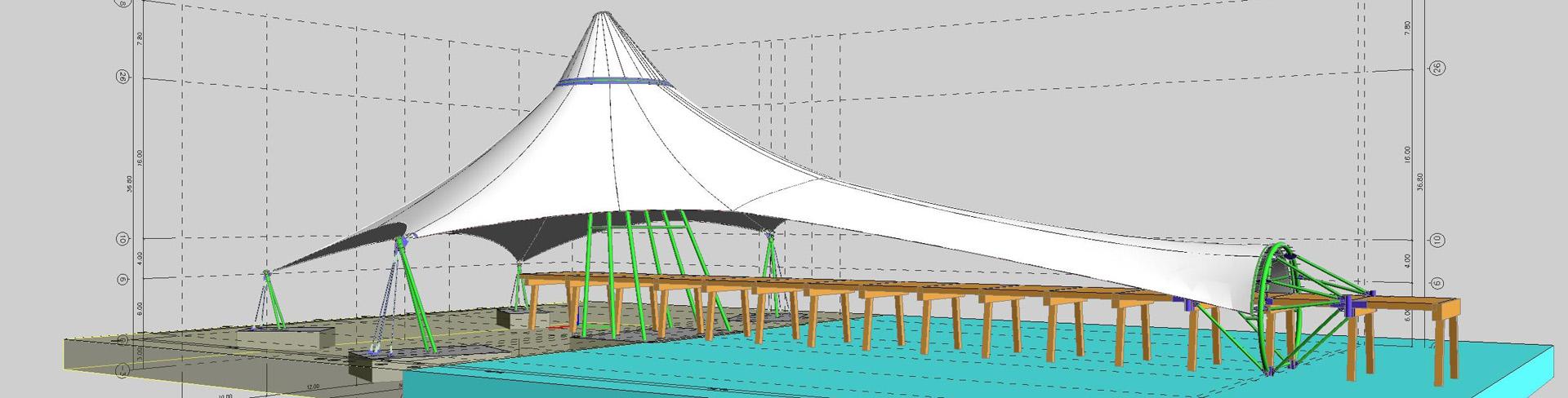
Membranes
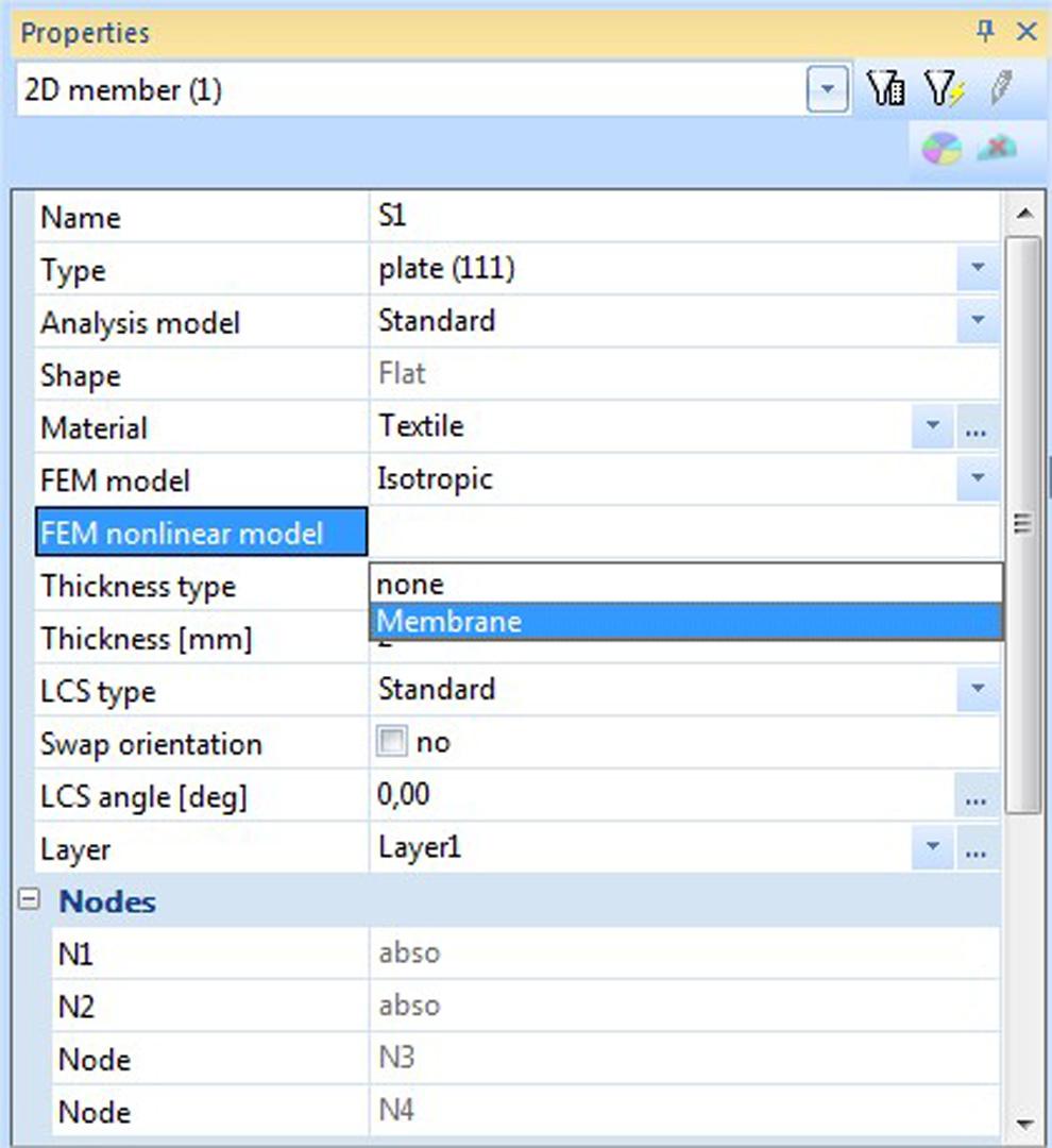
This module offers the possibility to use membrane elements. Membrane elements are defined as shell elements with no flexural stiffness and no axial compression stiffness. Membrane elements can thus be used to model canvas, nets, etc. that are subjected to axial tension.
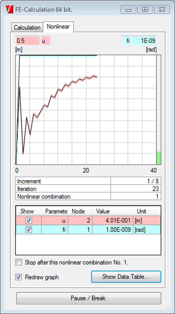
To obtain realistic results, a 2nd order calculation needs to be executed using the Newton-Raphson method.
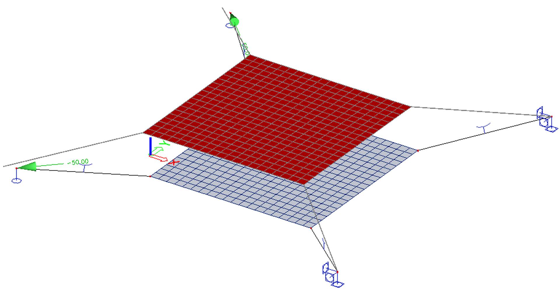
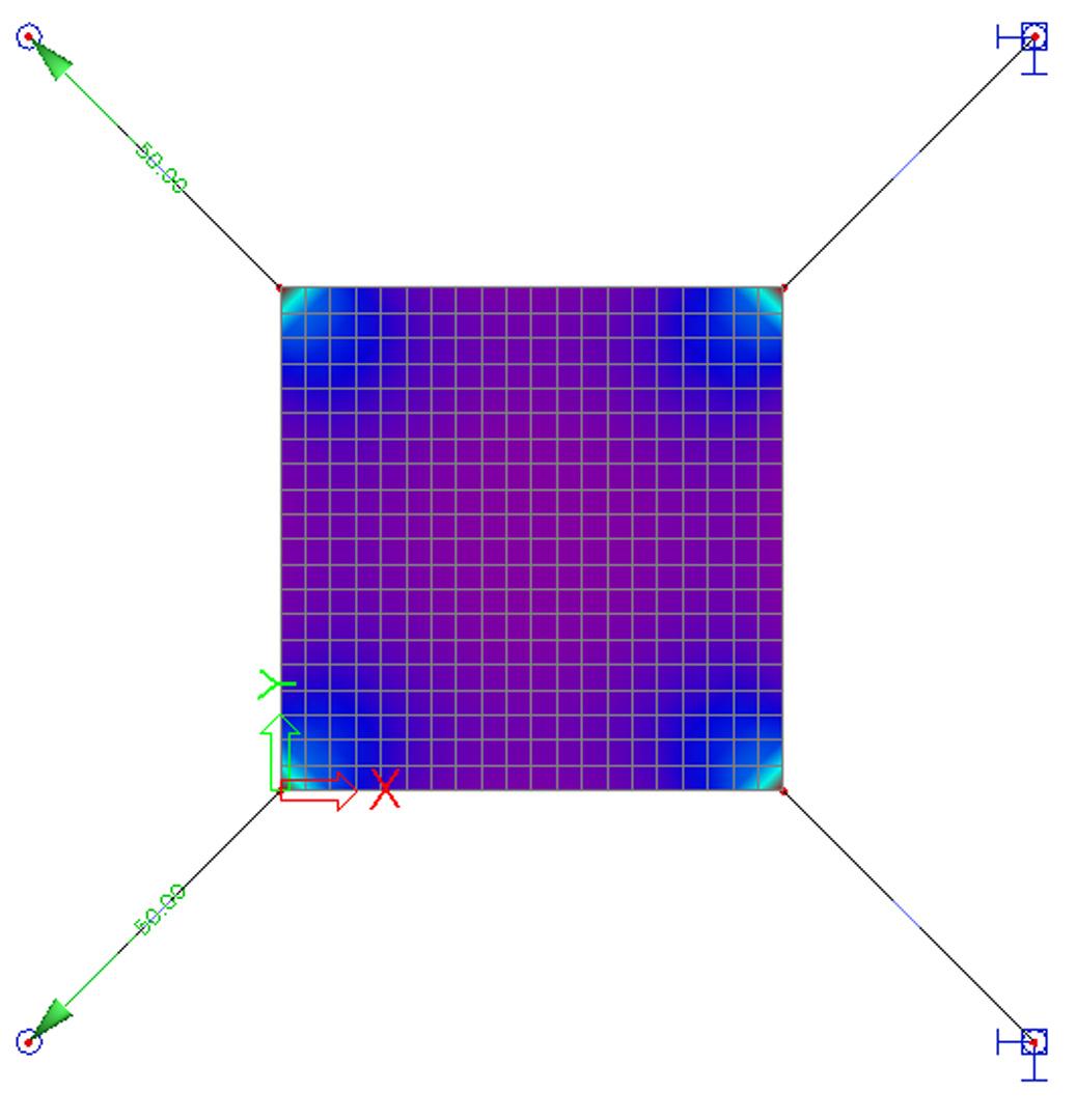
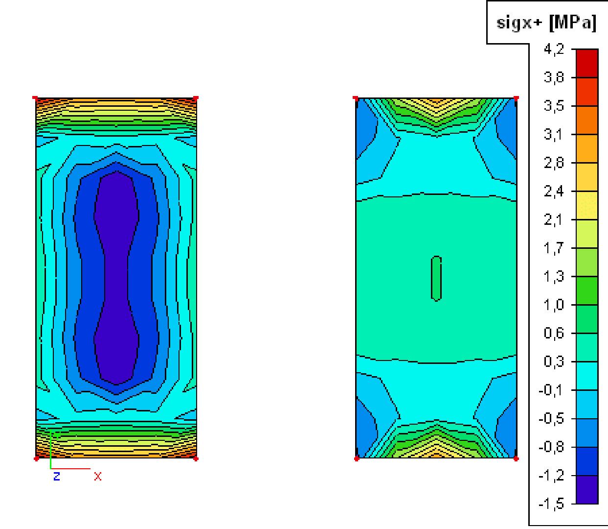
Differences in the results between membrane and standard element
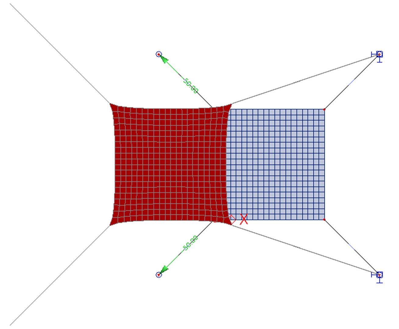
The difference in the obtained results stemming from the application of the membrane behaviour can be best demonstrated on a simple example. Let us assume a rectangular plate made of a very thin sheet of steel. The left-hand side of the figure shows the results obtained for a standard 2D element. The right-hand side then contains the results for the membrane elements.
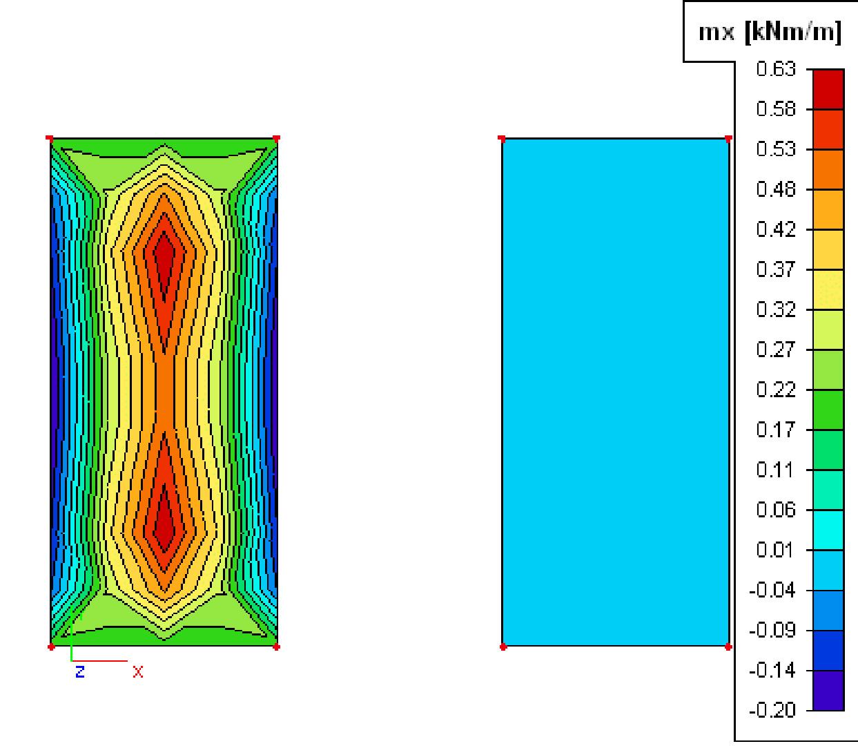
Note: Membrane elements can only be modelled in a General XYZ environment. Due to the fact the flexural rigidity is zero, no ribs, no prestressed tendons, orthotropic parameters or physical non-linear data can be input on a membrane element. Since a membrane element has no axial compression stiffness, no concrete calculation nor CDD can be performed on this type of element.
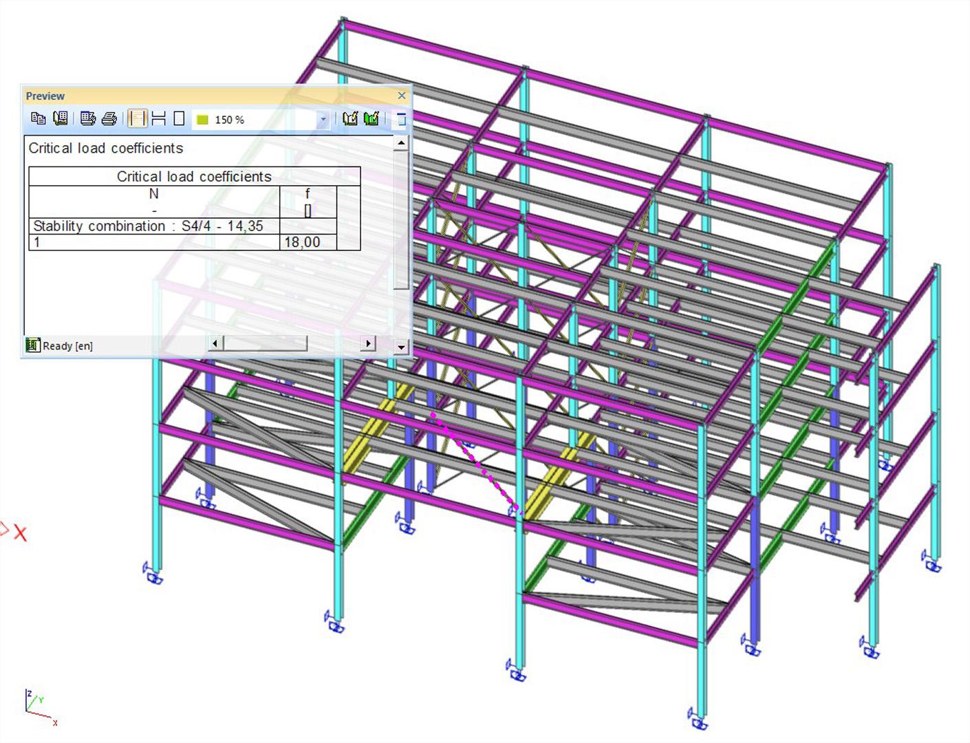
Non-linear stability analysis
Stability calculations are used to obtain an insight into the buckling mechanisms of a structure, to calculate the buckling length of a member for use in the steel code check, to verify if 2nd order calculation is required, etc.
This module helps determine the global critical buckling mode and buckling load of frame structures while considering nonlinear effects. Calculation is done in two stages. The first stage increases the load incrementally to the point of structure instability taking nonlinear effects into consideration. The second stage determines the buckling mode and buckling loads.
If you know the buckling load, you can determine for each structure whether a second order calculation is required. The building codes provide the limits for using the first order calculations in terms of loading and buckling loads.
You can derive the critical initial deformation for a second order calculation from the global buckling mode of the structure.
Required modules:
- sens.00

Want to try SCIA Engineer yourself?
Explore how our software and services can help you optimise your work and boost your productivity. Try it for yourself with a free 30-day software trial.
Download a free 30-days full trial