
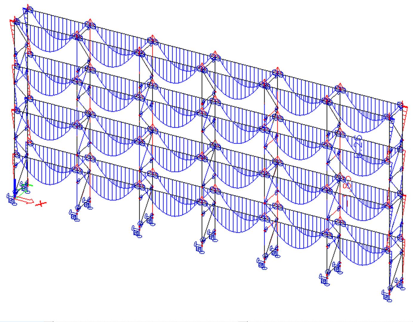
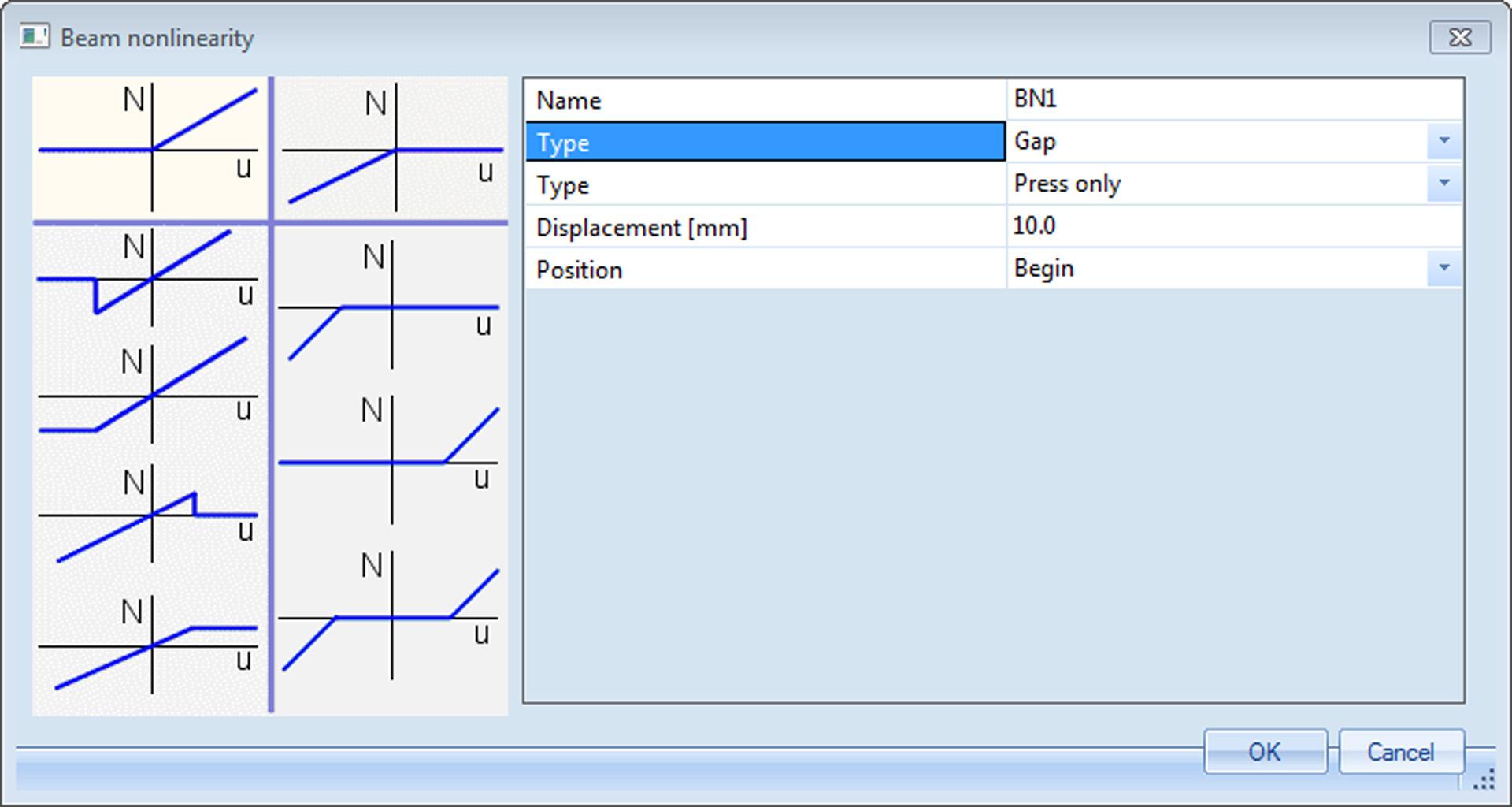
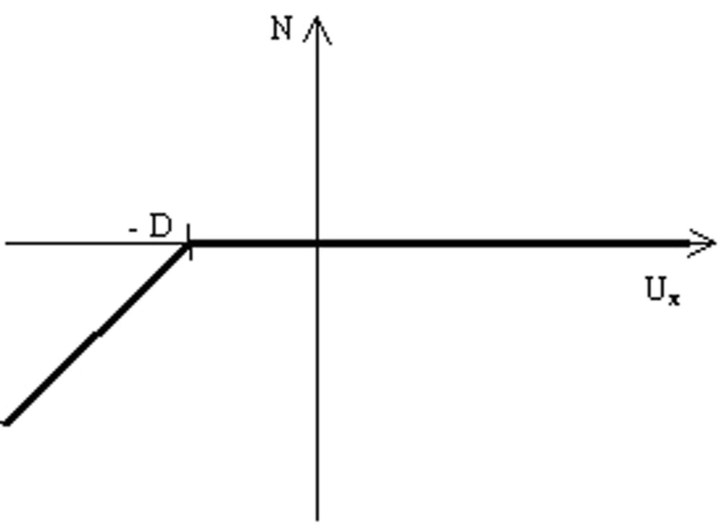
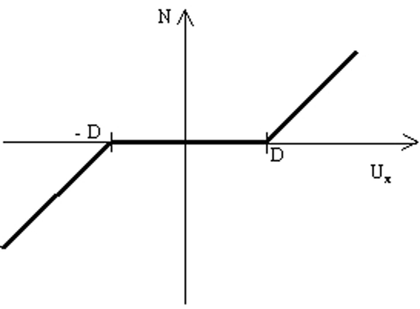
sens.00 - Basic non-linear analysis

  • Module code sens.00
  • Software
    • SCIA Engineer
  • Included in editions
    • Concept,
    • Professional,
    • Expert,
    • Ultimate
  • Category Analysis & Results
  • License Perpetual

Highlights

  • Easy-to-use modelling of special types of structural members.
  • Simple application of special types of analysis.
  • Possibility to run multiple analysis (linear, non-linear ...) in a batch.
  • Manual and automatic mesh refinement.

This module deals with basic non-linear analysis of frame structures as well as surfaces. It also allows you to use non-linear supports and hinges for the analysis.

2nd order analysis

This module allows you to perform second order calculations. It includes the calculation of the structure in deformed condition, taking into account the P-Delta effect (initial displacements and member imperfections) as well as the influence of normal forces on the stiffness.

Second order analysis can be performed on initially deformed structure taking into account geometric imperfection (initial deformations and member imperfections):

  • Bow imperfection specified by the user or according to Eurocode
  • Global imperfection specified by the user or according to Eurocode
  • General buckling shape from the stability analysis

Two calculation methods available are:

  • The Timoshenko method can assess building structures with small horizontal deformations where the normal force in the elements remains constant during second-order calculations;
  • The Newton-Raphson method determines effects under gradually applied loads. This method is optimal for structures with significant deformations, where the normal force in elements changes during calculations.

Non-linear hinges/supports

Analysis of the structure with the possibility to define non-linear springs in supports or internal nodes (e.g. semi-rigid connections) and gap elements (e.g. members resisting forces only as of a certain elongation). For each degree of freedom (X, Y, Z, Rx, Ry, Rz) a nonlinear function can be input. The function signifies the relation between moment and rotation or force and displacement.

Non-linear springs for supports and internal hinges

Parameters of a non-linear support can be divided into two groups:

  • Stiffness - This basic stiffness is used for the initial linear calculation.
  • Function - The function defines non-linear behaviour of the support. This function is taken into account during the non-linear calculation.

Non-linear function manager

Non-linear function that specifies the behaviour of a non-linear support can be defined in a standard SCIA Engineer database manager. The function itself consists of a positive and negative branch. The function must always pass the zero point, i.e. the zero displacement must correspond to zero force. Any "switchbacks" in the diagram are not allowed.

This means that e.g. the positive branch may rise or keep a constant force value, but it is not possible to let the force go down with increasing displacement. In addition to the function itself, there is a special parameter for the positive and negative axis. Values of this parameter are:

  • Rigid - If ON, the support is considered infinitely rigid once the limit displacement (the last input displacement value defined in the diagram) is reached.
  • Free - If ON, the support is considered free once the limit displacement (the last input displacement value defined in the diagram) is reached.
  • Flexible - If ON, the stiffness of the support is considered constant once the limit displacement (the last input displacement value defined in the diagram) is reached. The force value specified for the last input displacement is used.

Example of use of non-linear springs in pallet racking

Gap elements

(e.g. elements taking normal force after an elongation of 10 mm)

There are various connection and support conditions used in a real structure. It may happen that a 1D member is not attached rigidly to the structure but "starts its action" only after some initial change of its length. The behaviour of such a beam is defined by the absolute value of the initial "slip". The member starts to transfer the load only after its elongation or shortening reaches the input value. There are three options available:

no tension - Modelling e.g. the instant when a 1D member is “leaned” against a support.

no compression - Modelling e.g. a free rope

free in both directions - E.g. a scaffold pipe.

All 1D members are tested and processed simultaneously in every iteration step. The procedure is iterative and converges to the correct solution. 1D members inserted into the model may be again eliminated in a next step if their deformation gets under the input value if initial displacement ("slip"). The convergence speed is high and does not depend on the number of 1D members. Eight to ten iteration steps should be enough for a common structure.

When inserted into the model, a 1D member with this type of nonlinearity is marked by the following symbol (remember that in order to see the symbol, view parameters must be adjusted to show model data).

Analysis of the structure with the possibility to define members capable of resisting only to tension or compressive forces or a limited compression or tension. A practical application is the elimination of compression in wind bracing.

Tension only members

It is possible to define a member with following non-linearity types:

  • Pressure only: the member is only active under pressure (i.e. strut, …)
  • Tension only: the member is only active under tension (i.e. anchor, diagonal, …)
  • Limit force: the member acts in the structure until a specified limit is reached after which the member will be eliminated from the calculation or yields plastically.

Note: When using this type of beam non-linearity, it can happen that numerically a very small pressure/tensile force remains in the member, mostly due to its self-weight. This value will always be negligible compared to the other force components in the member.

Note: It is important to keep in mind that ‘Tension only’ does not change anything for shear forces and moments. The only component which cannot occur is compression, but the member can still be subjected to bending, torsion,... To specify that a member can only be subjected to normal forces, the FEM type of the member can be set to axial force only.


Required modules:

  • sen.00
SCIA Engineer free trial

Want to try SCIA ENGINEER yourself?

Explore how our software and services can help you optimise your work and boost your productivity. Try it for yourself with a free 30-day software trial.

Download a free 30-days full trial  

Request an offer for SCIA Engineer

Contact support for more technical information