Highlights
- Easy-to-use graphical user interface
- Planar and curved surfaces including their intersection
- Full control over the display style including perspective, rendering, activity, colour management, etc.
- Independent analysis and structural model which means both accurate results and realistic and nice-looking pictures
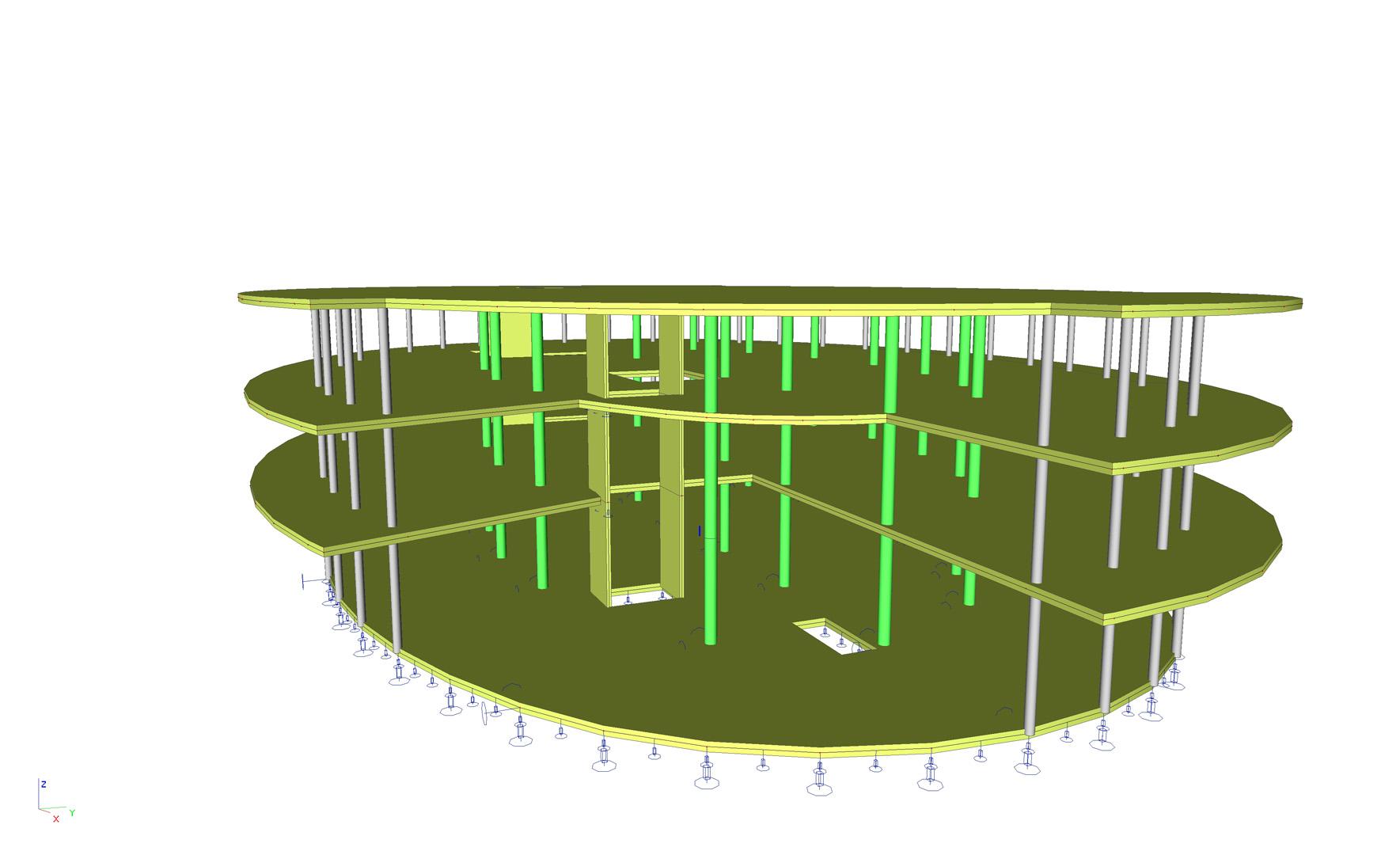
This module enables you to input flat or curved surfaces in the environment of SCIA Engineer. Planar or curved surfaces may have defined straight or curved edges, constant or variable thickness, specific boundary conditions such as ribs, openings, subregions or cut-outs defined by intersecting surfaces. Surface, line or nodal forces may be applied, and nodal and edge supports may be defined. You can use specific tools to create and edit the topology of planar elements, generate FE mesh on them and enable them in the FE analysis. Furthermore, a whole set of results on surfaces is available. All tools and functions described in module scia.m.frame are available for planar elements as well.
Planar and curved surfaces
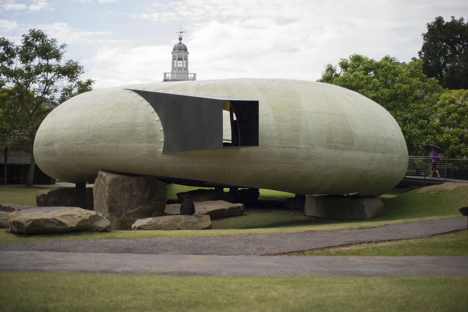
Not only planar, but also curved surfaces (members) can be modelled. The structure may contain e.g. cylinders, cones, hyperboloids, spirals and other simpler or complex shapes. From a mathematical point of view all these surfaces are defined as arbitrary quadrilaterals or triangles. The shape of the edges then specifies the shape of the final surface.
Once a curved surface (member) is inputted, it can be edited using standard functions for geometric manipulation. The edges can also be edited and, if required, their shape can be altered e.g. from Bezier curve to a line or vice versa.
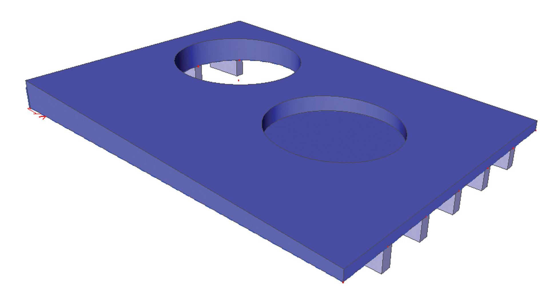
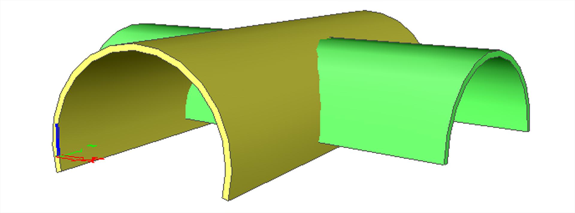
Cut-outs of 2D members
This feature extends the possibilities of SCIA Engineer by generating intersections of 2D members. Under certain circumstances the generation of the intersection (i.e. the intersection line or curve) is sufficient, for example when you need to connect a plate and a wall so that they “know” about each other and act as one unit. On the other hand, especially curved surfaces require more than a simple calculation of the intersection curve. It is usually necessary to remove a part of the structure on one side of the intersection and to keep just the other part.
The action is then split into 2 steps:
- calculation of the intersection (i.e. intersecting curve)
- removal of the part (the "cut-out") that should not be taken into account in the calculation (when exists)

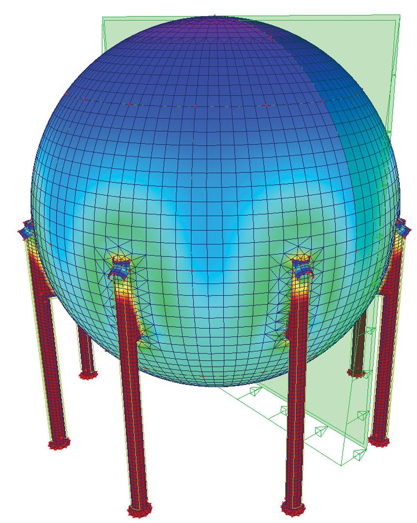
Linear analysis of planar elements
Module scia.m.surface extends the FE analysis capabilities described in module scia.m.frame by the possibility of generating mesh on planar elements (slabs, walls, shells) and performing FE analysis with them. FE analysis results can be viewed and evaluated in several ways.
Clear and detailed results
- Diagrams on the model: diagrams of result values drawn on the model in 3D graphical window
- Resultants: loads, reactions, forces in sections
- Detailed results on separate planar and shell elements: detailed evaluation of results and diagrams element by element
- Comprehensive report about the calculation
- Engineering Report: combination of tables and pictures in a structured report
- Table Results: all results values in a tabular form (with an optional export to MS Excel
Comprehensive results
Slabs, walls and shells allow following options for drawing of results on planes:
- isobands / isolines
- resultants
- local and global extremes
Each type of basic results on planar elements is supported by several tools for convenient and quick display of results in selected areas:
- integration strips
- sections
- averaging strips
- integration members
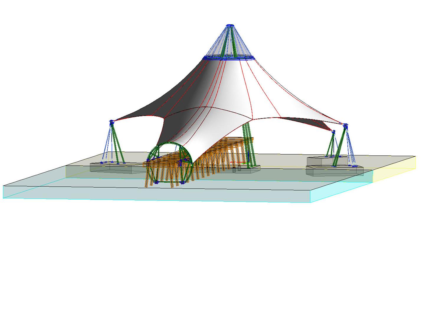
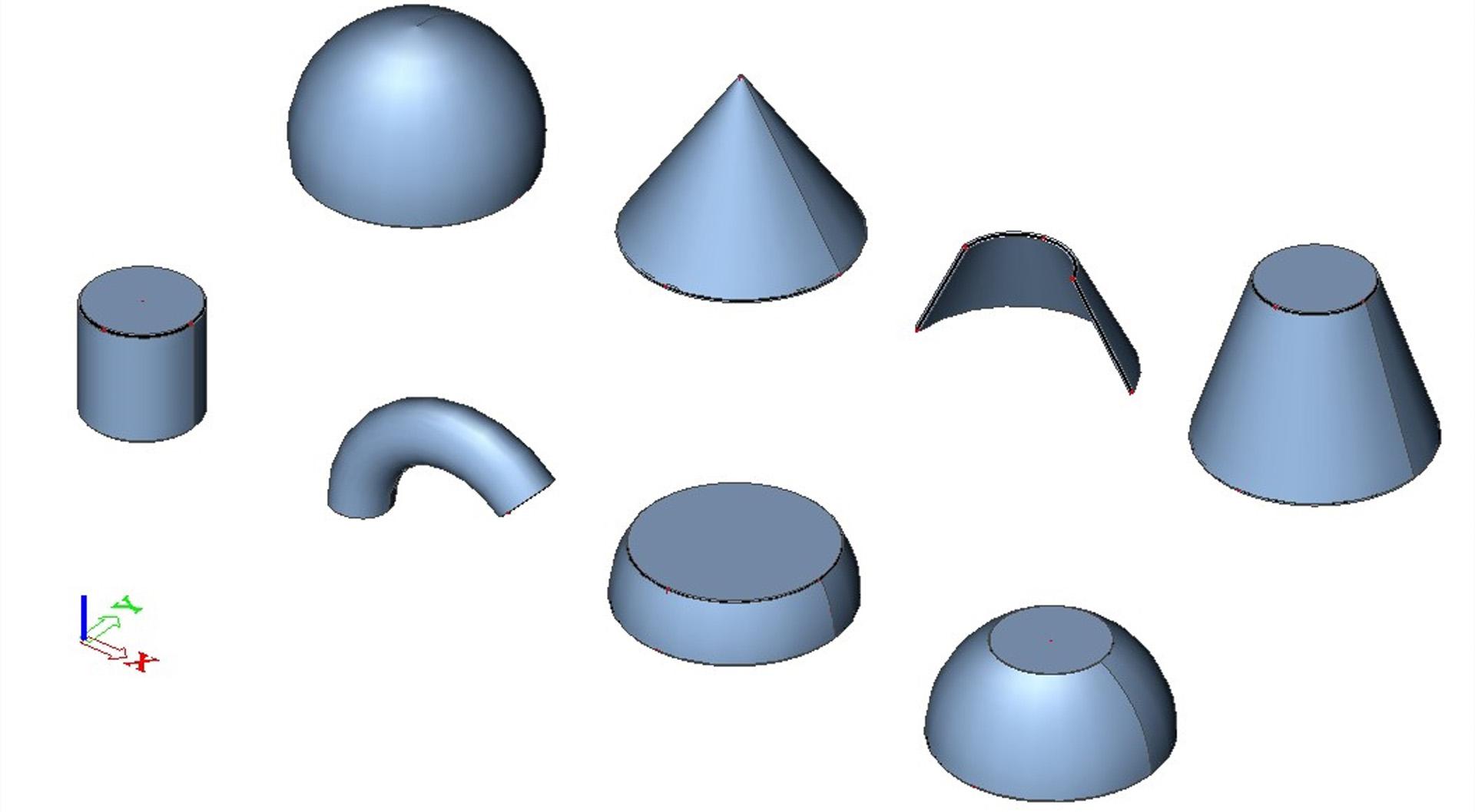
3D Freeform modeller
The 3D Freeform modeller is a tool for modelling of 3D volumetric shapes, primarily devoted for use in structural engineering. It offers all the benefits of full 3D modelling, such as making input in any direction or plane in 3D, rendered or transparent display of edited entities.
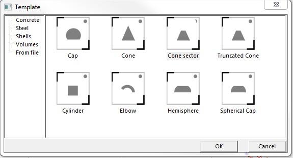
The basic solid modelling features are located under service Structure => Modelling/Drawing => Solid. Basic available types are:
- Prism
- Cylinder
- Surface of revolution
Next to these general 3D volumes, there are also open shell-types:
- Open shell - general polygon
- Open shell - surface of revolution
- Open shell - swept surface
This default set can also be extended by the user with the “Parametric modelling” module scia.m.parametric.
The 3D Freeform modeller handles volumes, which are basically based on curved shapes. All definition curves can be edited by moving their definition points in a very fast and intuitive way.
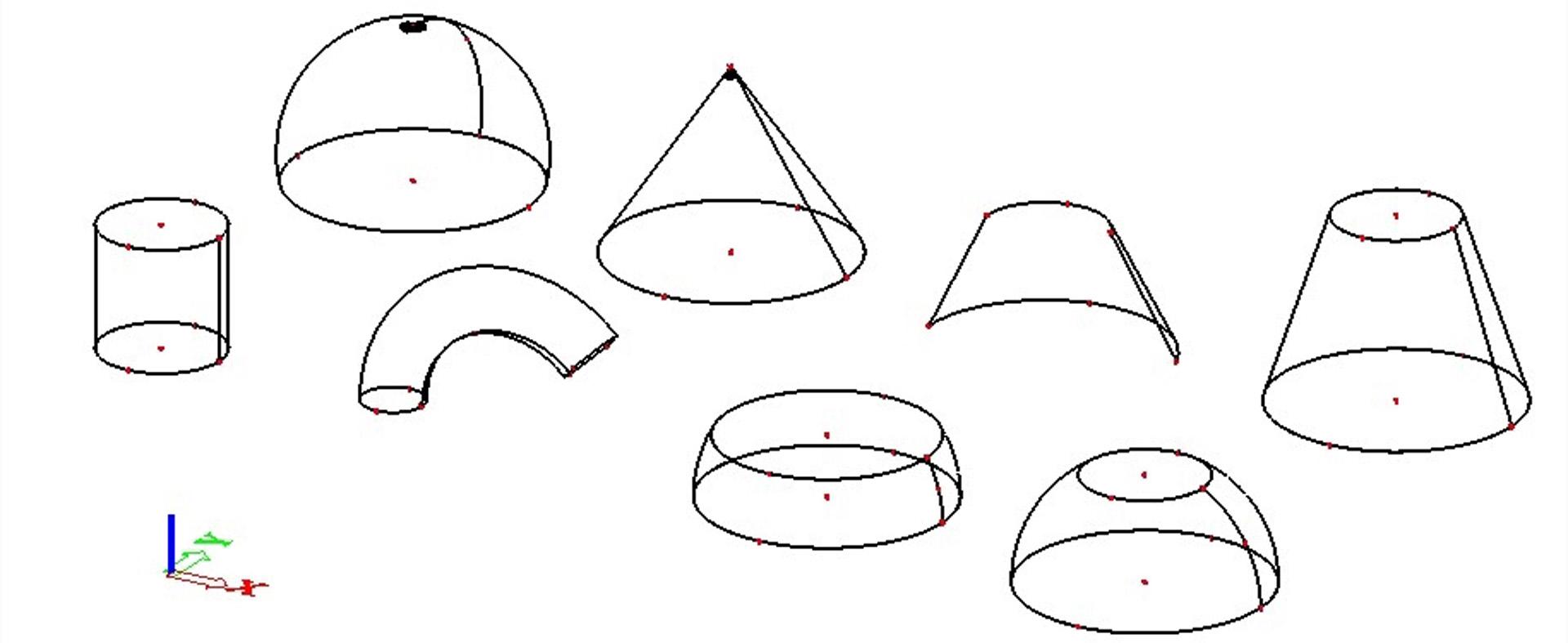
This approach allows creating almost any shape quite easily.
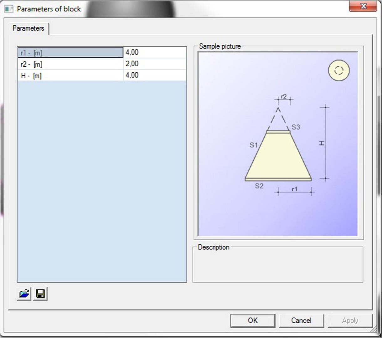
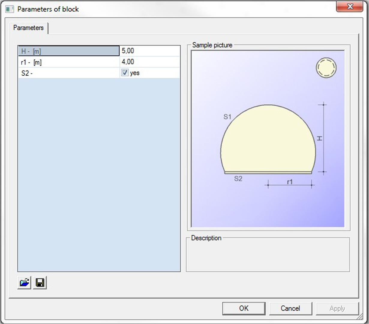
The predefined shapes follow the same logic as any other block in SCIA Engineer. You can set parameters in the dialog, but once placed in the model space the shape is fixed and no longer parametrically editable. Advanced modelling of general solids, such as extruded solids, solids of revolution, etc. Boolean operations, namely intersection, union, subtraction, can be applied to solids together with sophisticated functions for the modification of solid shape (meshing of surfaces, geometrical manipulations with nodes).
Volumetric shapes can be created in 2 ways: extrusion or rotation. Any line or edge can be straight or curved, so it is possible to create a large variety of shapes.
All curves keep their type and can be edited any time later. All curves/lines follow the position of their definition points, so fast and easy editing is possible by moving those points with any of the geometry editing functions. Regular “move”, “scale”, “stretch” functions can be used as well as numerical editing of coordinates of vertexes by the table-edit function. Parametrisation is available as in other SCIA Engineer entities, so volumes can be used to create parametric templates without any limitations. For parametrisation is required “Parametric modelling scia.m.parametric.
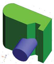
3D Boolean operations
Boolean operations are a standard tool for the efficient modelling of 3D shapes. The 3D modeller supports all common operations:
- Union
- Subtraction
- Intersection (XOR)
- Division (OR)
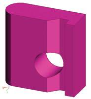
As mentioned above, 3D modeller is equipped with a set of functions for efficient lateral modification of solids. This is based on the technology of multilevel definition of surfaces, which allows handling both primary and also secondary level geometry definition, which is, created by means of internal distinctness of surface faces.

Want to try SCIA Engineer yourself?
Explore how our software and services can help you optimise your work and boost your productivity. Try it for yourself with a free 30-day software trial.
Download a free 30-days full trial