Concrete usability improvements
Single concrete setup & views
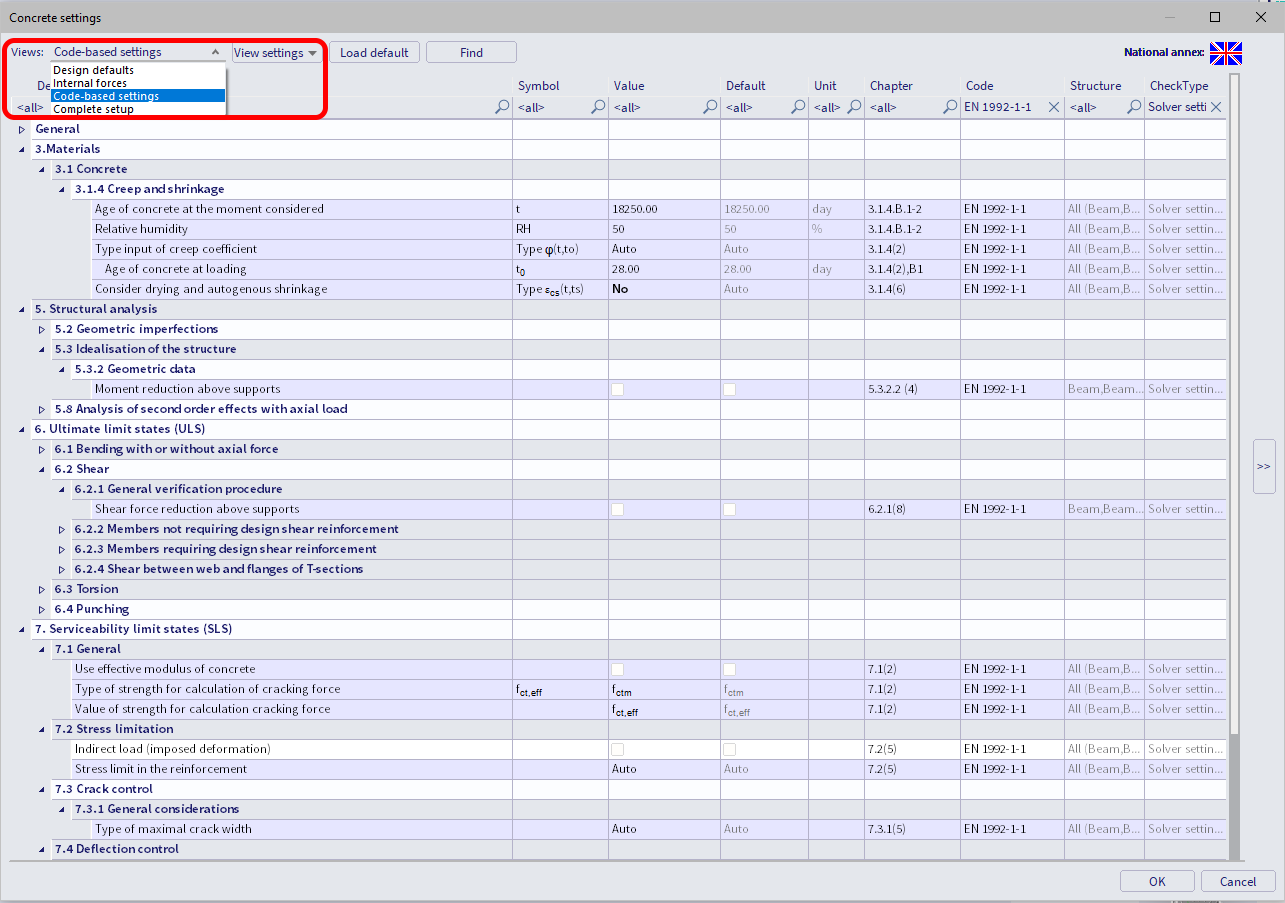
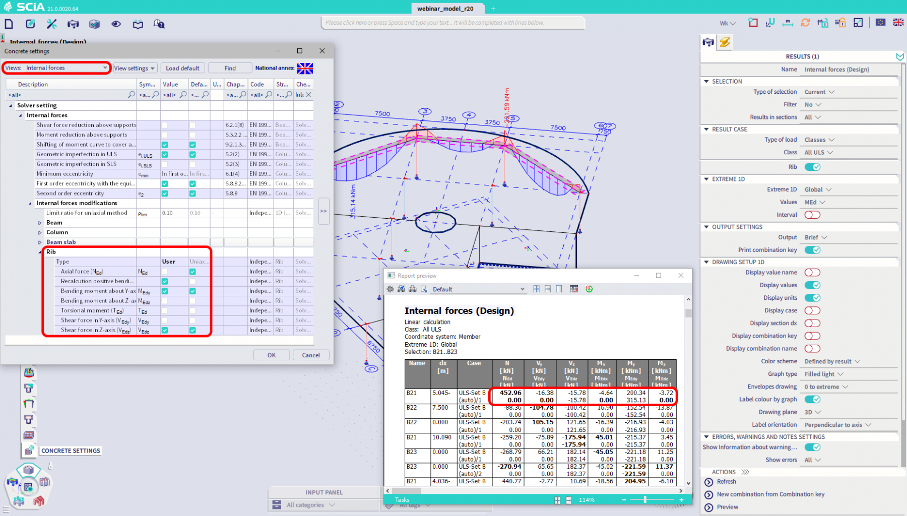
The most visible change is the unification of the Concrete setup. There is no more searching between two menus for general rules and settings for the reinforcement design. All the options can now be found in a single place. Moreover, the content of the setup is now easily customizable by filtering the items through the "Views" feature. The pre-defined views represent the most popular/important categories to be quickly accessible for modification. More advanced customization can be achieved by creating and storing user-defined views that are simple to share via *.vws files.
Transparent input of initial diameter
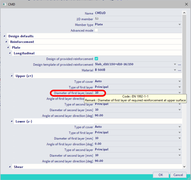
There is an improved way the initial diameter for the design of the required reinforcement areas is defined. The diameter is no longer derived as originally from a design template of the provided rebars. Newly it's introduced as a separate input in the Concrete setup / Concrete member data. This arrangement enables you to fully control what effective depth is used for each reinforcement layer through the whole design procedure.
Quick edit of provided reinforcement
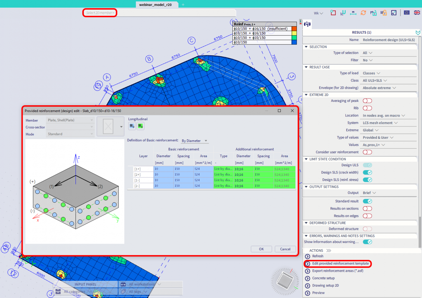
A new action button is available in the 1D & 2D reinforcement design commands to quickly invoke the dialog for edit provided reinforcement template on the selected 1D or 2D member. Suppose the edited template is also assigned to another concrete member/s. You can either apply the changes there or keep the rest untouched by the automated creation of a new template from the original one with modified values assigned only to the selected member.
Speed-up 2D reinforcement design
A significant speed-up of 2D reinforcement design is achieved in version 21 due to having the required reinforcement independent on the definition of provided reinforcement. Newly, the required areas are not recalculated each time the assumption about the provided rebars is changed. Instead, the areas are kept in the memory and reused to decrease the total calculation time by about 50%.
Non-designable areas of 2d reinforcement
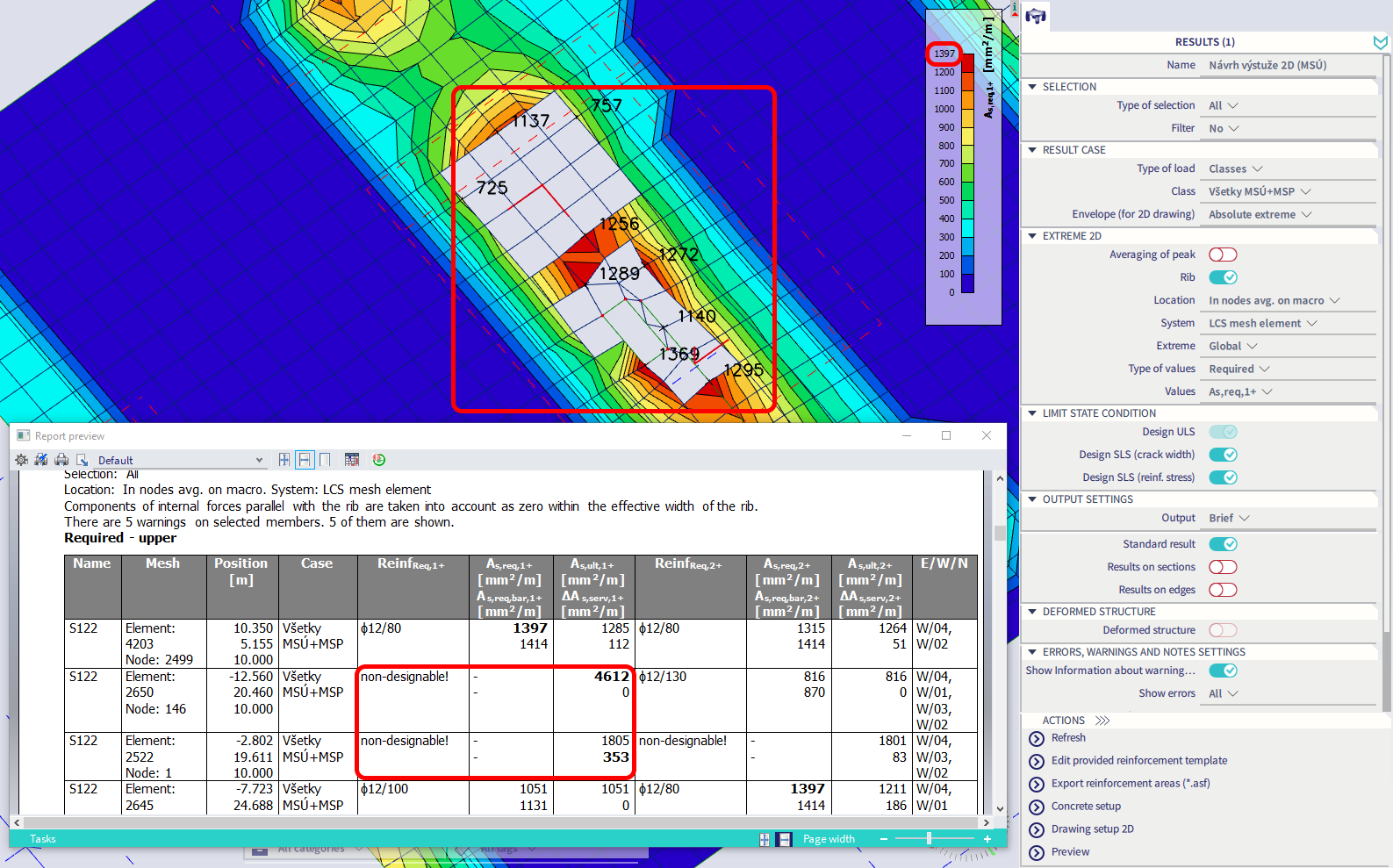
The required reinforcement (As,req) on 2D members bigger than the defined maximum value (As,max) is now limited. Such places are marked as non-designable, meaning that the results there are not available. This modification automatically improves the graphical presentation of the required reinforcement areas to be not corrupted by the peak values (there is no need for manual adaptation of the colour palette). Another motivation was to avoid using an unrealistic amount of designed reinforcement in the concrete checks (like Code-dependent deflection). That means, the non-designable areas of the reinforcement are newly considered zero there not overestimating the member's stiffness.
Modification of internal forces in 1D design
A common problem in previous versions was the difficulty in settings of 1D design forces to ignore some internal forces component/s to simulate, for instance, pure uniaxial loading with or without torsion specifically just for ribs. Such an option is now available in the Concrete setup (or Concrete member data if you want to apply the modification individually for some member.) This functionality gives you full control over what internal forces are considered in both the design and checks of 1D concrete members.
Design by checks for 1D reinforcement
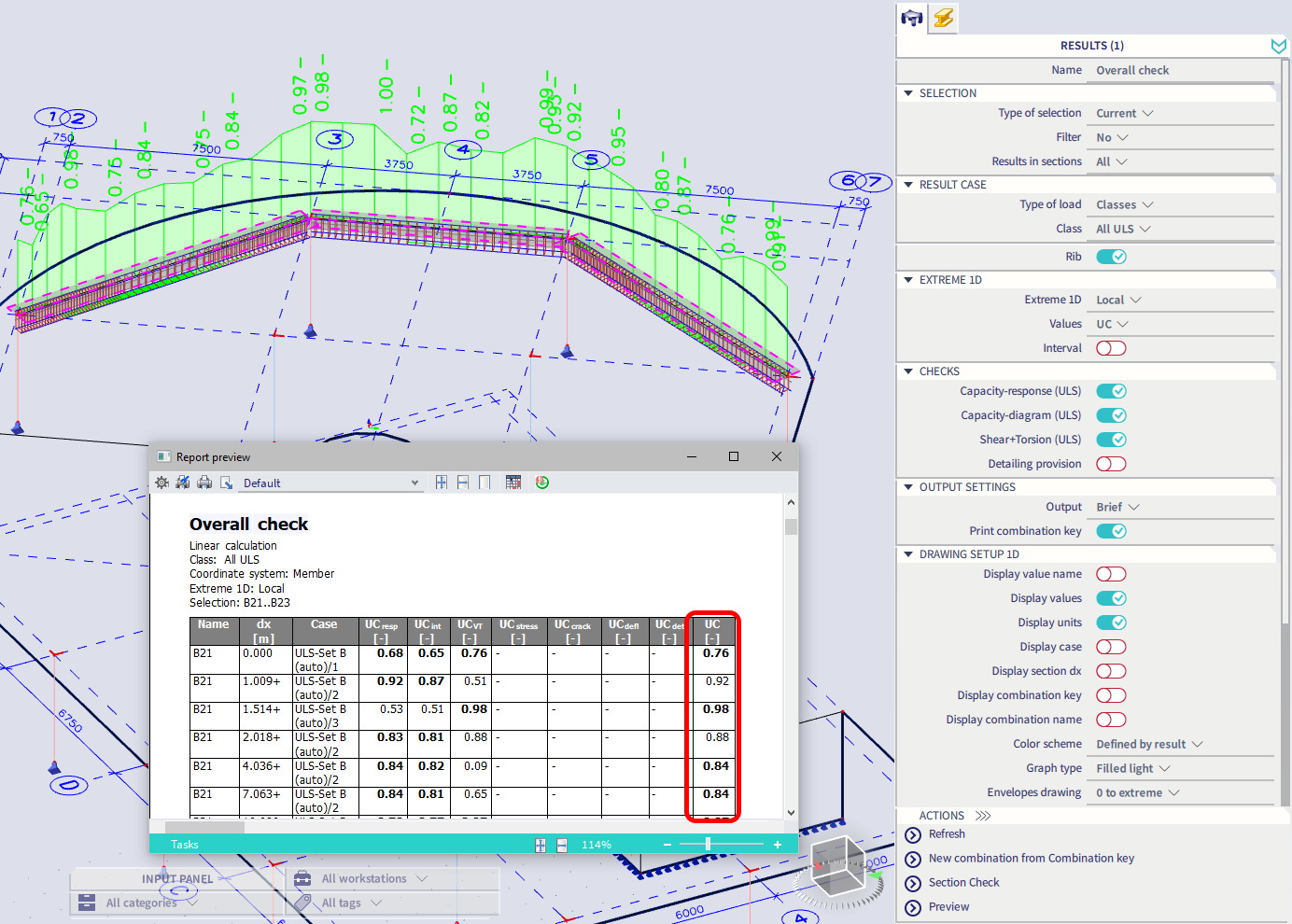
The reinforcement design procedure for beams and columns is newly optimized by iterative use of the concrete checks. This improvement ensures that the designed reinforcement is always sufficient and economical, with the utilization factor very close to the limit value (UC < 1.0) for the critical sections.
Code-dependent deflections improvements
In the SCIA Engineer, the Code dependent deflection (CDD) command serves for a fast and reliable check of the long-term deflection of reinforced concrete members (like beams, ribs or slabs) according to Eurocode 2. With version 21, a significant extension of the module has been introduced to improve its overall usability.
Considering shrinkage
Concrete shrinkage is a phenomenon consisting of intrinsic rheological deformations that are not related to mechanical loads yet may significantly impact the final deflection. It is caused by structural changes occurring in the cement paste due to the physico-chemical processes of water loss resulting from the setting, hardening and drying of concrete.
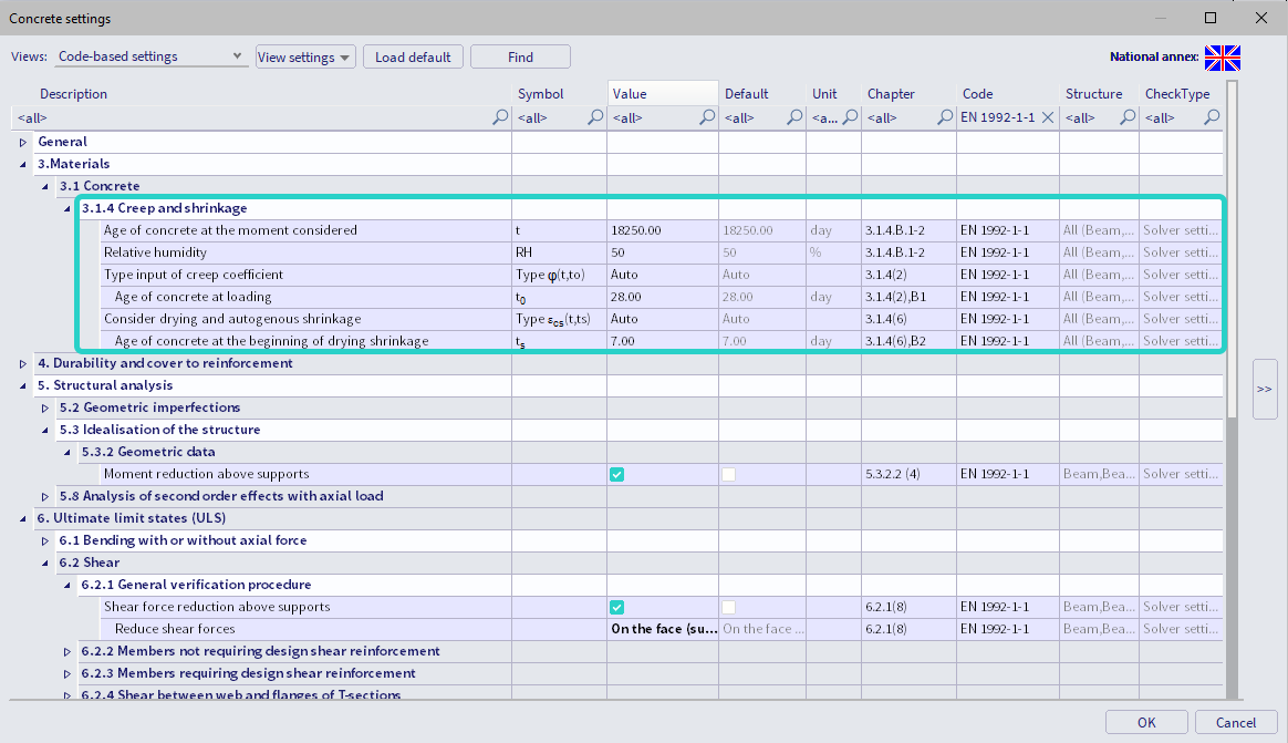
Total deformation due to shrinkage (δshr) is the sum of two components: autogenous shrinkage and drying. Newly it's possible to include both parts into the calculation of CDD. To do this, a user has to activate one of the following options in the Concrete setup: an automated way where the shrinkage strain εcs(t,ts) is calculated acc. to clause 3.1.4(6) in EN 1992-1-1 or choose manual input instead. Both options can also be applied specifically for selected 1D or 2D members using the Concrete member data.
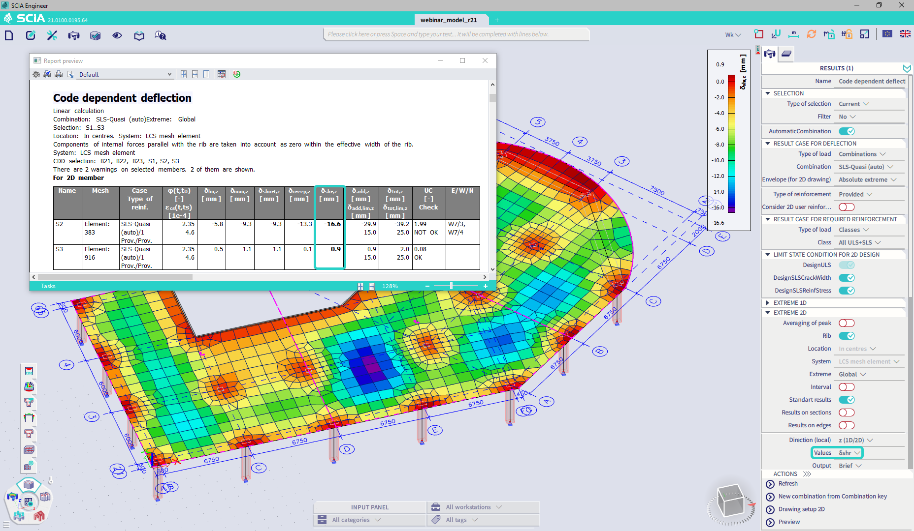
Once the shrinkage strain is known, the curvature caused by the shrinkage is determined, taking into account the applied reinforcement on the member. The deflection δshr is then calculated using the stiffnesses derived from this curvature and the load level assumed for the total deflection. It means shrinkage is always thought of as part of a long-term effect similar to creep. The deflection due to shrinkage can be visualized separately in both graphical and numerical output to investigate its contribution to total/additional deflection.
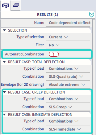
Manual input of load combinations
In general, the check of deflection acc. 7.4.1(4,5) in EN 1992-1-1 should satisfy the following conditions: the appearance and general usability of the structure is ensured by limiting the total deflection (δtot). In contrast, possible damage of adjacent parts of the structure caused by the deflection after the construction is avoided by restricting the additional deflection (δadd).
The EN code prescribes a different load input to analyze both deflection limits. In the previous version of CDD, only the combination given for calculating the total deflection has been required as the user's input. The rest of the necessary sub-combinations to evaluate creep and the immediate part of the deflection are automatically generated by the program. Newly, the manual input of those combinations is also allowed. It's just necessary to deactivate the automated generation of combinations in the CDD command and select some existing linear combinations for both stages instead.
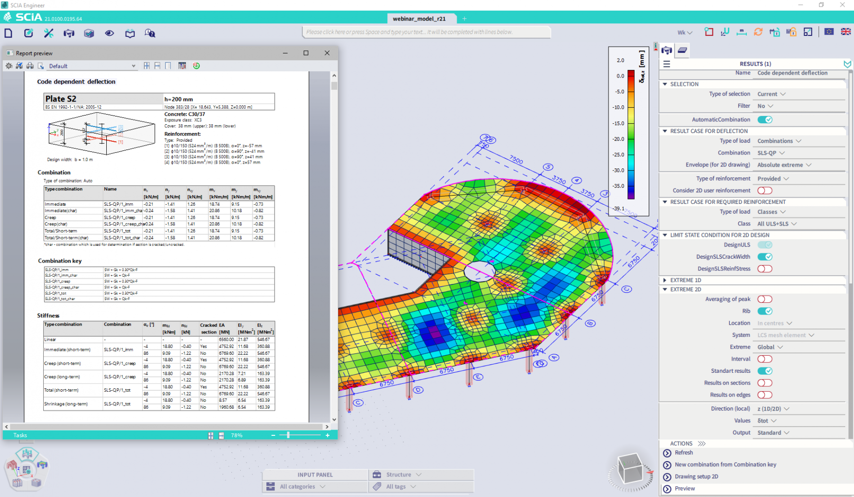
Standard/detailed output
Making the code-dependent deflection analysis more transparent for the users, the standard and detailed output are now available from the calculation. Results of any mesh element on 1D or 2D member can be investigated in detail using the standard approach. It's only necessary to select this option in the command properties or use Table results to display the report for specific extreme presented as a row in the table (by double click on it). The following information is part of the output:
- load combinations used in the calculation (name, combi-key, internal forces)
- calculated stiffnesses for all the loading levels (uncracked and cracked state, distribution factor ζ, …)
- details about the calculation of the creep and shrinkage effects
Steel-design extensions
Utilisation factor
In version 21 the implementation of the valorisation project SEMI-COMP+ n° RFS2-CT-2010-00023 has been extended with the introduction of the utilisation factor η. It allows the use of less conservative section classes for the EC3 stability checks, which can lead to considerable material savings.
The current problematic
Stability effects are influenced by the properties along the entire length of a member. Therefore, the highest section class along the member is currently used as the class for the stability checks. This approach is a very conservative one, as the position of this highest class is not always relevant. For this reason, a new method based on the utilisation factor has been introduced.
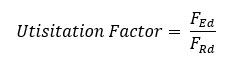
What is the utilisation factor?
The utilisation factor is a measure for how close a section is to using its maximal section capacity. It is determined by proportionally increasing the loading until the design resistance of the cross-section is reached. The utilisation factor is then obtained by the ratio between the applied loads and the loads at the design resistance.
Classification using utilisation factor
Instead of simply using the highest class along the member, the SEMI-COMP+ project proposes to use the class of the section with the highest utilisation factor. Or, in other words, to use the class of the most utilised section along the beam.
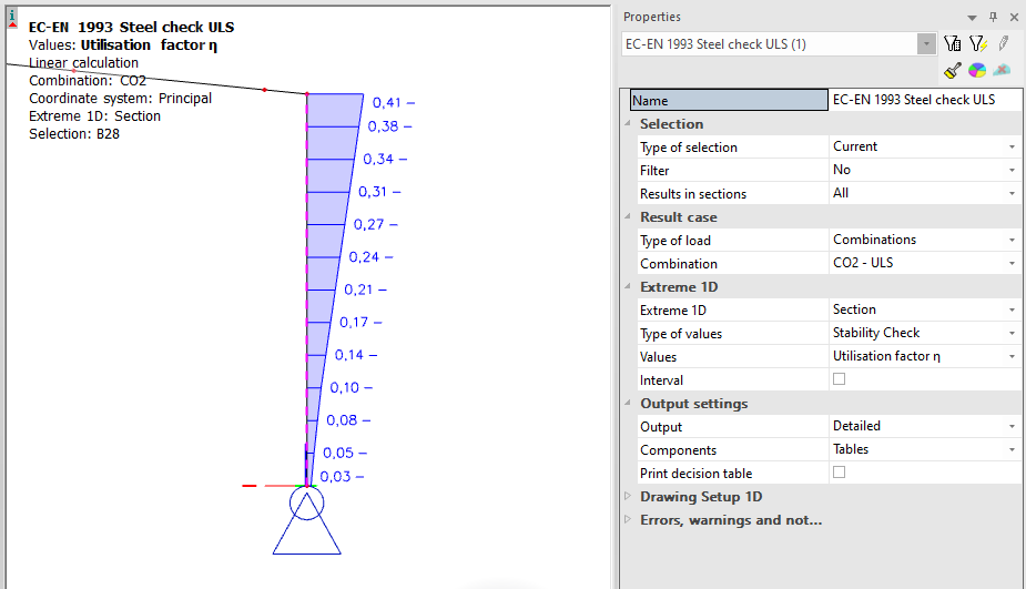
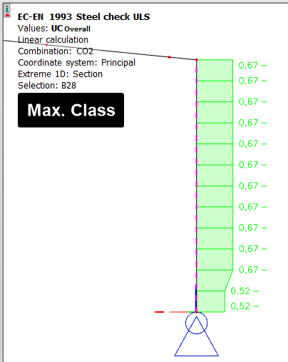
For example, in this column the highest class is found at the level of the hinge, where the column is in full compression. According to the old method the stability checks would be executed with class 4 section properties.
When we plot out the utilisation factor, we observe that the forces at the level of the hinges are very small compared to the maximum resistance. The class 4 sections are not relevant sections in the behaviour of this column.
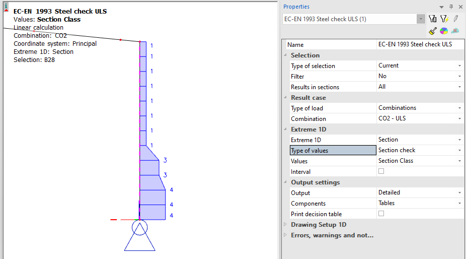
Using the utilisation factor method, this column will be checked using class 1 section properties. In this particular case, it leads to around 10% material savings.

Inside SCIA Engineer
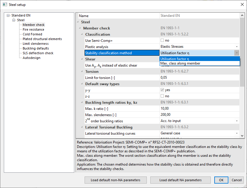
The preferred method for the stability classification can be selected in the steel setup.
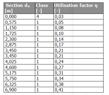
When choosing the utilisation factor, the output of the steel code check shows the decisive utilisation factor and its position along the member.
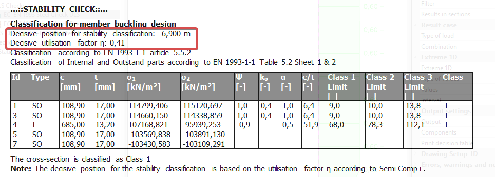
A table with the utilisation factor in each section can be printed as well by activating the decision tables.
The benefits
Make full use of the thoroughly researched and certified Semi-Comp+ guidelines to design according to EC3. Steer clear of old, conservative methods and allow the utilisation factor to bring you economical designs, save material, and stay ahead of your competition!
Model modifiers for modal and seismic calculation
Introduction:
As indicated in paragraph 4.3.1 of EC 1998-1 the elastic flexural and shear stiffness properties of concrete and masonry elements should be reduced to half to take into account effect of cracking of the load baring elements during seismic calculation. In the past this was task not easy to do. It was either possible to define modifiers for all load cases (ppe v16 and older) or to assign it to specific load case (ppe default) but with exception of seismic load cases.
In version SCIA Engineer 21 new option to use model modifiers for seismic load cases and modal calculation has been introduced.
Description:
In the past, a user was able to use property modifiers and attach them to 1D and 2D members. The drawback of that approach was that the modification was valid for all load cases. In version SCIA Engineer 19.0 new feature called property modifiers per load case has been introduced. This feature allowed users to define modifiers dedicated to particular load case. Unfortunately, it was not possible to use this feature for seismic load case.
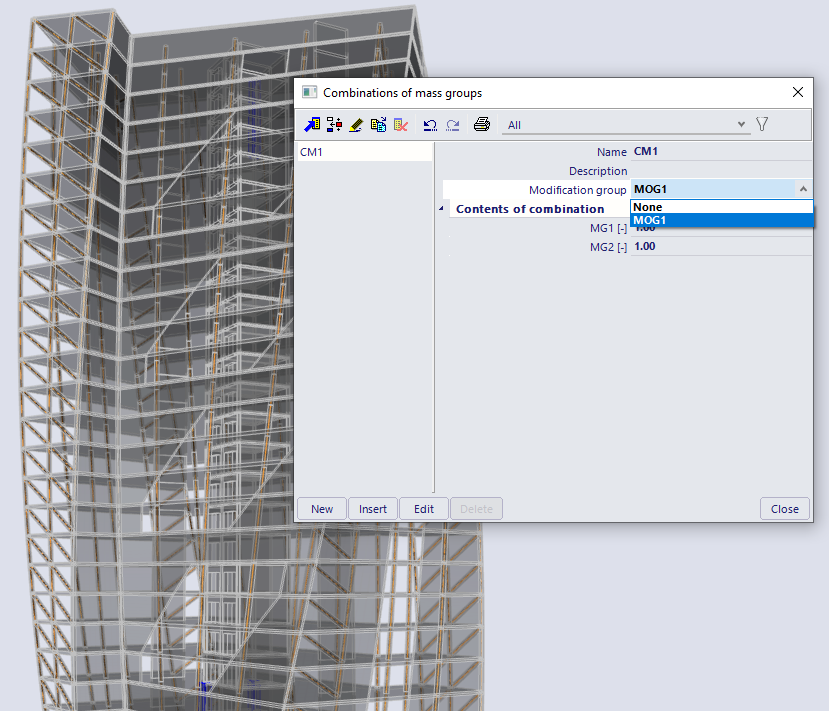
In version SCIA Engineer 21 you may assign modification group to a Combination of mass groups. Such Modification group is than taken into account during the modal analyses.
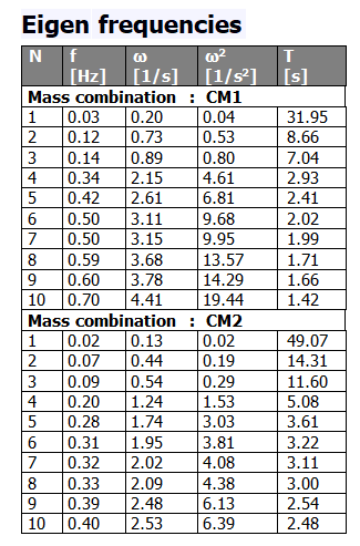
As result of that you may easily verify the impact of stiffness reduction on the eigen frequencies of the structure.
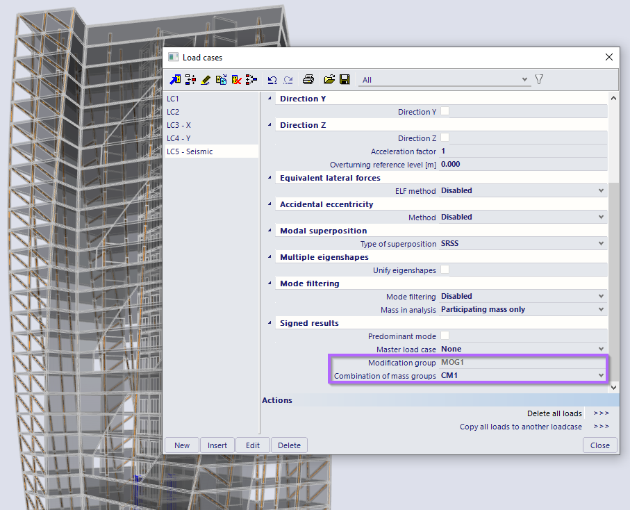
And in case such Combination of mass groups is than used as a reference for results of modal analyses for seismic load case, the Modification group is than automatically assigned accordingly.
To prevent possible discrepancies the field for definition of the Modification group for Seismic load cases is not editable as it is linked to the settings in the Combination of mass groups dialogue.
Following model modifiers are supported:
- Support absences
- 1D absences
- 2D absences
- Subregion absences
- 1D stiffness modifications
- 2D stiffness modifications
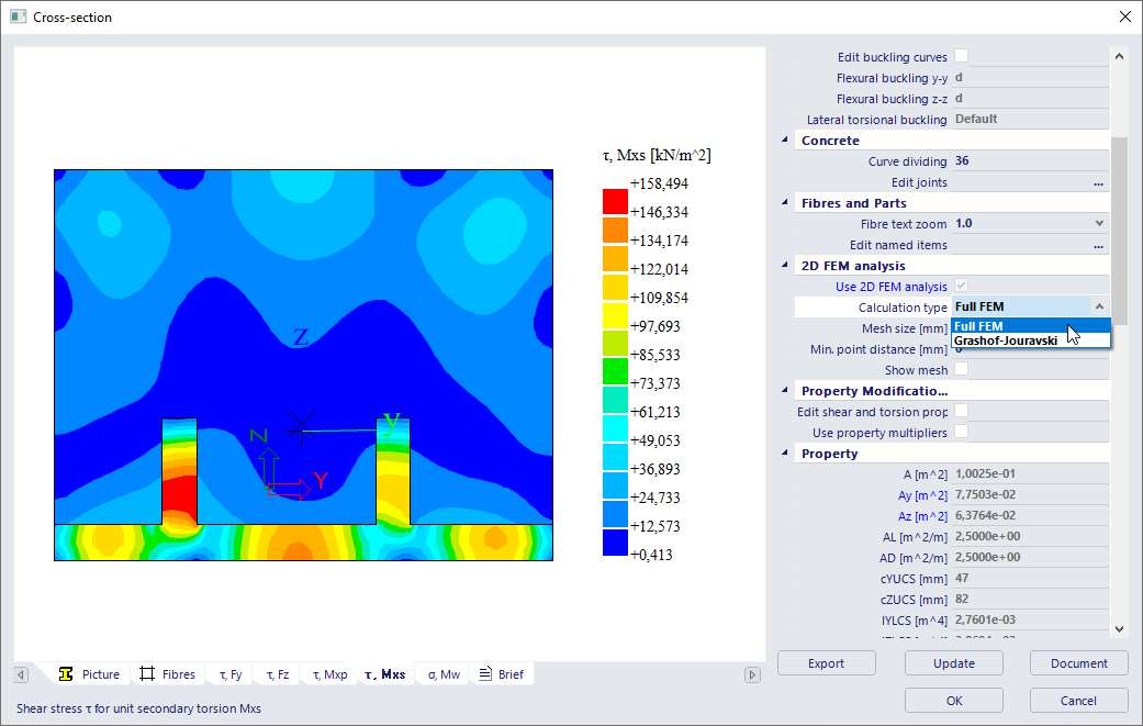
New method for the calculation of section properties using the finite element method
Version 21 of SCIA Engineer brings a new method for the calculation of section properties using the finite element method. This method overcomes the limitations of the currently implemented Grashof-Jouravski method. It allows for the correct calculation of shear, torsion and warping stresses for any cross-section shape, including composed sections and sections with large openings.
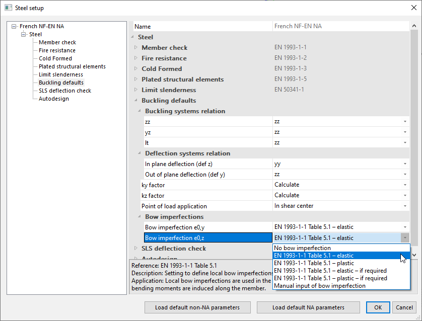
Bow imperfection defaults
Forget inputting buckling groups on all the elements in your project to take into account bow imperfections. Version 21 brings you a default setting for bow imperfections inside the material setup. Input imperfections on all your steel, timber, composite and aluminum members in just a few clicks.
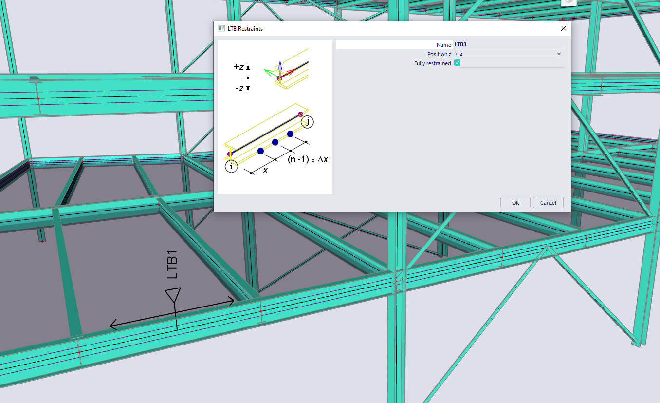
Full length LTB restraints
Thanks to your votes on the user poll it will now be possible to define lateral torsional buckling restraints over the full length of a member. In case a member is fully restrained, the LTB-check will simply be skipped with a note stating that the member is supported over its full length.
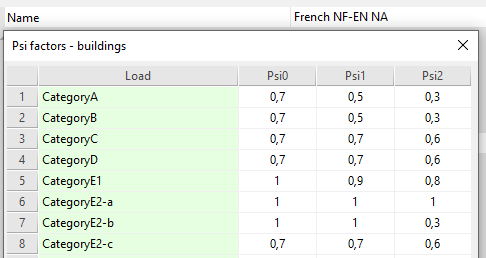
Cat E adaptation for France
The French national annex support has been updated to incorporate the latest new rules for Category E loading. When opening your project in the new version you will now find the possibility to select category E1 or E2(a,b,c) loading when using the NA for France.

Want to try SCIA Engineer yourself?
Explore how our software and services can help you optimise your work and boost your productivity. Try it for yourself with a free 30-day software trial.
Download a free 30-days full trial