
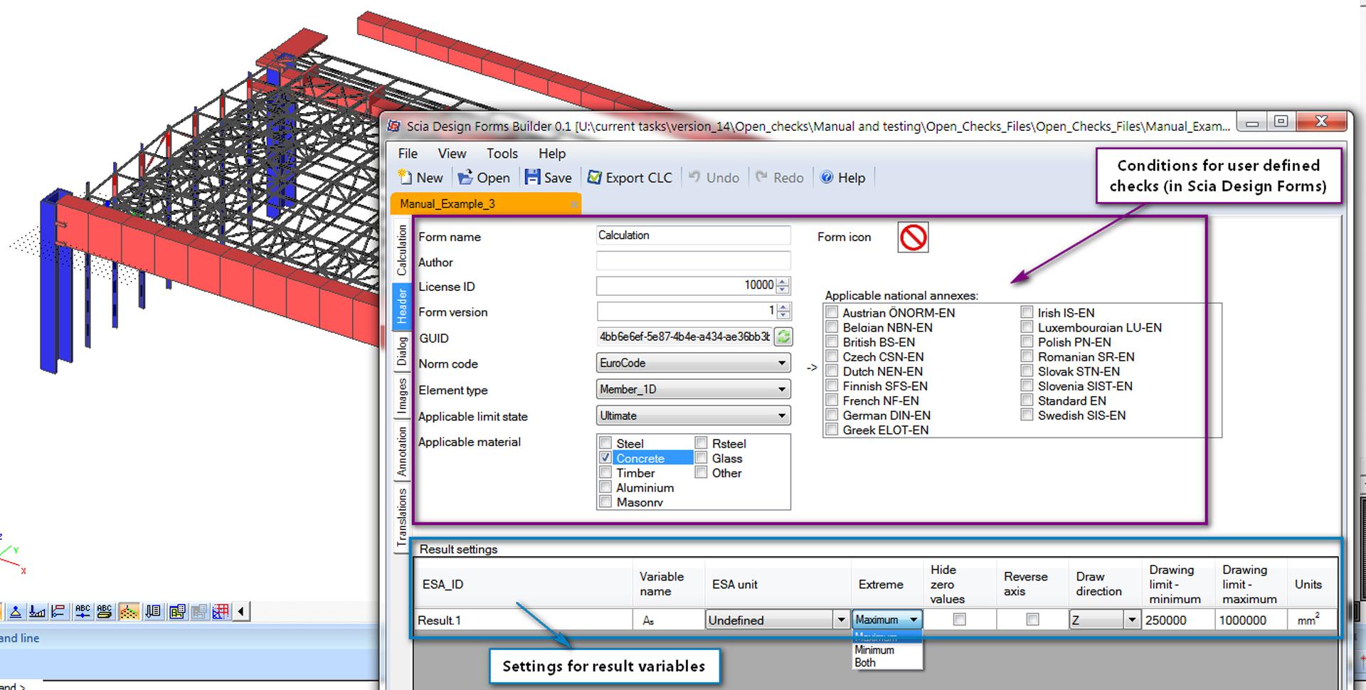
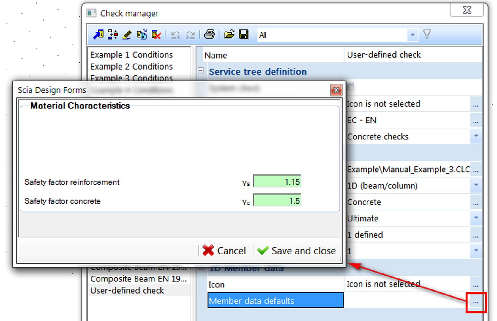
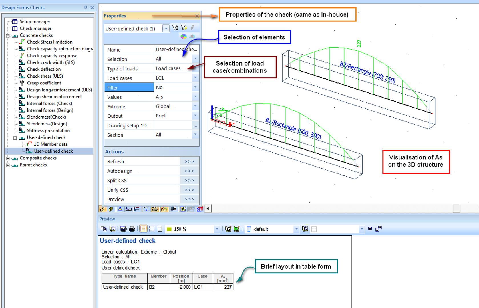
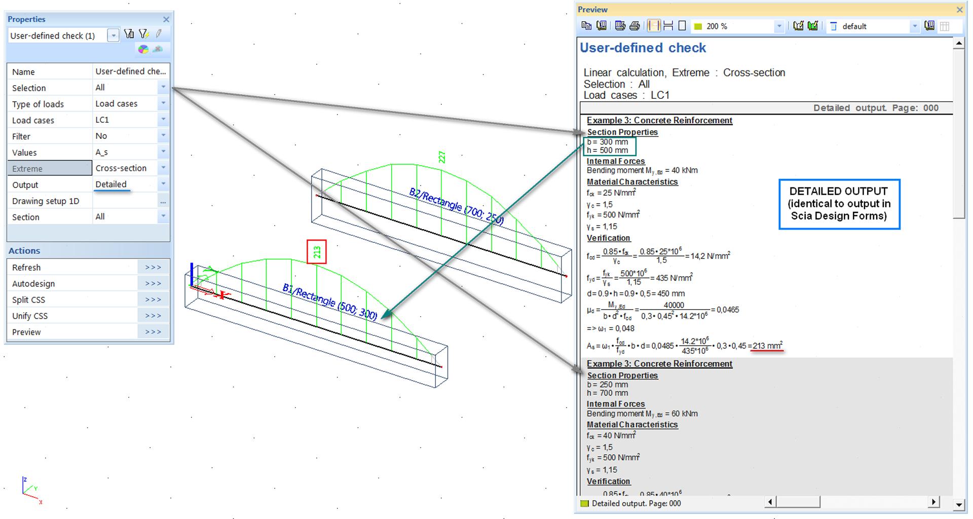
sen.07 - Open Design

  • Module code sen.07
  • Software
    • SCIA Engineer
  • Included in editions
    • Professional,
    • Expert,
    • Ultimate
  • Category Other topics
  • License Perpetual

Highlights

  • Freedom to create your own calculation algorithms and use the graphical, computational and reporting capabilities of SCIA Engineer to execute them.
  • A fully integrated solution that does not require retyping of data, cell mapping of spreadsheets, or scrutiny of transferred data during the checks.
  • Intelligent handling of variables, units, graphical display, user-defined menus and trees.
  • High calculation speed due to parallel processing and file-free transfer of data inside the open platform.
  • Support for AutoDesign optimisation for 1D steel members within the SCIA Engineer Profile Library.
  • Export of calculation reports to project documentation in the Engineering Report

SCIA Engineer offers users the possibility to implement their own engineering calculations and use these as plug-in checks during their everyday work with CAE projects -- e.g. in a graphical review of overall capacity in a 3D structure, in an AutoDesign optimisation, and in reporting. Design checks related to:

  • the resistance or stability of members with irregular geometry, or of members made from new materials,
  • the adequacy of section size and reinforcement area according to local standards which we do not currently support,
  • foundation checks based on sophisticated deformation theories,

are a few examples of what may, from now on, be added by end-user engineers via the easy-to-use open platform.

Introduction

SCIA Engineer automates a vast variety of design checks according to national and international standards.1D beams, 2D plates, 0D joints and supports may be verified according to rules given in codes, taking into account material characteristics, internal forces and other load effects that are either input in the CAE model or calculated during FEM-based analysis. Next to it, SCIA Engineer allows the users to link their own tailor-made checks and execute them using analysis data and FEM results from the 3D model. These user-defined checks are handled in the same way as the in-house checks.

Who is it for?

Users who perform structural analysis and standard checks in SCIA Engineer now have the possibility to add a missing special checks.

New checks are defined using an engineering platform called Design Forms. The versatile interface between SCIA Engineer and Design Forms guides the user through a simple, semi-automated linking process, while the results of the checks are displayed on the 3D structure and a report is send to the project documentation in the Engineering Report.

How it works

  • The Design Forms platform includes a set of functionalities that enable the simple programming of engineering calculations, handling of variables with units, creation of fine-tuned input dialogues and project documentation with graphical output and multiple layouts. The user writes the needed check as he would in the standalone version of Design Forms.
  • Input variables whose value should be taken from the CAE model are assigned standardized strings in Design Forms, e.g. InternalForces.My for the bending moment My per section of a beam. An exhaustive list of the accessible data from CAE models is available to the user.
  • Result variables may be printed graphically in the 3D window of SCIA Engineer. It is possible to define unit and entity type for each result variable, and options related to the graphical display - along which axis and in which direction should a result variable be printed, etc.
  • Conditions determine the check visibility in the menu of SCIA Engineer: for what type of members the check should be performed, which load combinations the check should use - for ULS or SLS, etc.
  • Referencing of input variables from the CAE model and the sending of calculated results back to SCIA Engineer happens directly via TCP/IP communication, ensuring high speed of the check execution.
  • The user may create and organise his/her own tree menu for custom checks in order to store all checks he would like to use. Menu trees may be saved and shared with other users, trees of multiple users can be merged in order to use checks defined on a number of PCs.

Advantages

User-defined checks based on the open platform of Design Forms are a step beyond linking spreadsheets made in MS Excel. Without cell mapping and with the intelligent handling of variables, the new solution is both simple and fool-proof.

  • Input data per member and input data for all members are handled separately, allowing for the definition of variable defaults;
  • Reuse of the input dialogue and calculation report created in Design Forms gives the user the freedom to customise his/her plug-in and create improved versions in the future. The graphical features of Design Forms make it possible to create tables, images, panels and tabs in the dialogue, and dynamic images, tables and graphs in the report.
  • The linking procedure is semi-automated, and it is possible to cross-check the data that are transferred.
  • A system of notes, warnings and error messages notifies the user when problems occur.
  • Usage and standard workflow for linking user-defined checks are explained in the manual and shown in examples.
  • Similar handling of user-defined and built-in checks -- when it comes to graphical display, units, warning and error messages, AutoDesign, reporting, and the transparent interface between SCIA Engineer and Design Forms -- is what makes the new open platform unique.

Main features

Design Forms Checks Menu

  • All new checks and menus for input data per check are stored in the same place - an item in the main tree of SCIA Engineer called "Integrated Design Forms."
  • The user may organise and customise this tree, assign icons to individual checks to make them easier to recognise.
  • He/she may save the tree and send it to other users, or he/she may integrate another user's tree into his own.

Conditions for User-defined checks

Conditions ensure the simplicity of the linking process:

  • A check type automatically determines the location in the tree menu - steel checks, concrete checks, other checks, etc.;
  • Norm code conditions limit the check visibility to projects where the selected code or national annex is active.
  • An element type determines for which elements the check should be executed - 1D members, 2D members, etc.
  • An applicable material condition determines for which members the check will be executed depending on the material that is assigned to the member in the model.
  • An applicable limit state condition determines which load combinations will be used during the check execution - ULS or SLS.

These conditions may be set both in Design Forms and in SCIA Engineer.

Reuse of the Design Forms dialogue

The API in SCIA Engineer displays the input dialogue as defined and visible in Design Forms.

  • No menu definition is required after linking;
  • The reuse of the input dialogue and calculation report created in Design Forms gives the user great freedom in organising his/her plug-in check - free arrangement for all items and support for any colour and shape are ensured.
  • The dialogue may be edited at any time in Design Forms.
  • The graphical features of Design Forms enable the user to have tables, images, panels and tabs in the dialogue, and dynamic images, tables and graphs in the report.

Calculation speed

  • Data transfer between the two applications (Design Forms and SCIA Engineer) is done directly via TCP/IP communication.
  • Checking multiple members is done by parallel processes - while the analysis is performed for one member, data is read for the following member.
  • The user may use application switches that allow him to list all data that is being transferred during the check - both names and values of variables.

Document support

  • A brief summary of all calculated data may be viewed and exported to the Engineering Report in table form.
  • The detailed check report is as designed in the source CLC file - this report is shown in SCIA Engineer, exported to the Engineering Report, and its layout may be edited in Design Forms BUILDER application.
  • Greek symbols, sub- and superscripts are supported.
  • Including user-defined checks in the document (Engineering Report) is supported.

AutoDesign

  • User-defined checks can use as input data the properties of cross-sections currently assigned to steel members in the 3D model.
  • Because of this, cross-section optimisation is performed in the same way as when in-house checks are called.
  • The AutoDesign feature browses though the profile library of SCIA Engineer and the classes of sections (IPE, HEA, etc.) defined there.

Required modules:

  • sen-00


SCIA Engineer free trial

Want to try SCIA ENGINEER yourself?

Explore how our software and services can help you optimise your work and boost your productivity. Try it for yourself with a free 30-day software trial.

Download a free 30-days full trial  

Request an offer for SCIA Engineer

Contact support for more technical information