Highlights
- Steel design according to EN 1993, AISC, SIA and NBR codes.
- Classification, ULS including stability, and SLS checks including camber design for all possible section shapes.
- Detailed output including formulas and references for a full transparency of the results.
- Fire and fire protection design according to EN 1993-1-2.
- Codes supplemented with the latest research and publications.
- Stability effects can be considered at the level of the check or through 2nd order analysis with imperfections.
- Automatic estimation of buckling lengths, or exact calculation through stability analysis.
- Optimization routines for quick and easy economical solutions.
The Steel Design module offers an interactive tool for section and stability design of steel members. From section classification to interaction checks for the various load effects on a member, SCIA Engineer guides you in achieving the optimal design with a minimal amount of manual input.
Supported Design Codes
For ULS design:
- EN 1993

- AISC 360

- SIA 263

- NBR 8800

For SLS design:
- EN 1993
- AISC 360
- SIA 263
For fire design:
- EN 1993
Supported National Annexes to the Eurocode:
Austria, Belgium, Czechia, Cyprus, Denmark, Finland, France, Italy, Germany, Greece, Ireland, Luxembourg, Malaysia, The Netherlands, Norway, Poland, Romania, Singapore, Slovakia, Slovenia, Spain, Sweden, United Kingdom. The choice of methods and coefficients specific per National Annex can be reviewed or adapted.
ULS Design
The ULS design allows to visualize and inspect the design outcome of steel elements for the internal forces obtained in the FE analysis, according to the chosen codes.
It also includes:
- Manual override of buckling factors
- Lateral torsional buckling restraints
- Consideration of sheeting & load positions
- Section warping in I-, U- and other thin-walled sections
- Calculation of battened compression members
- Accounting for web stiffeners
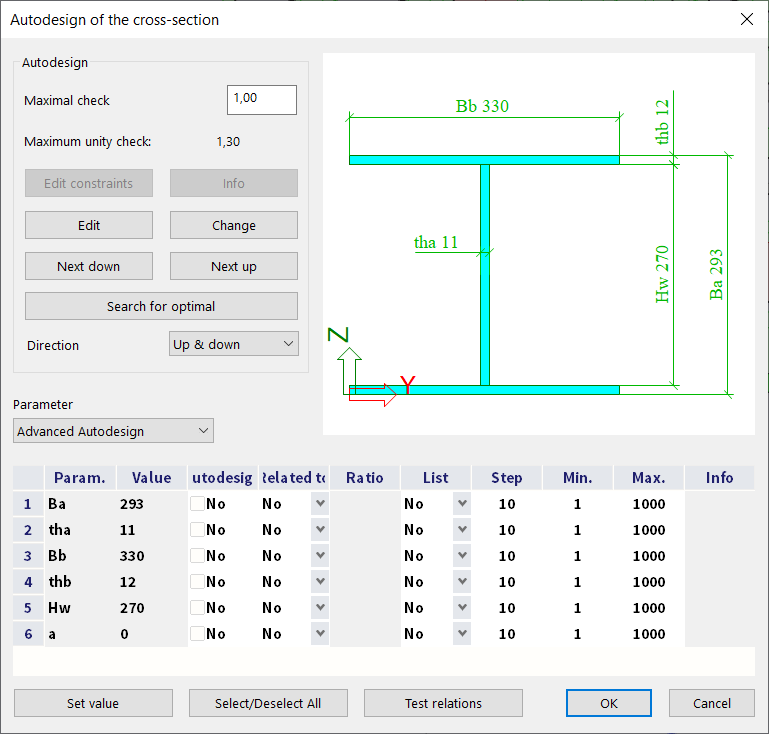
- Section optimizaiton routine
- Optional consideration of recent research and publications
Cross-sections & Classification
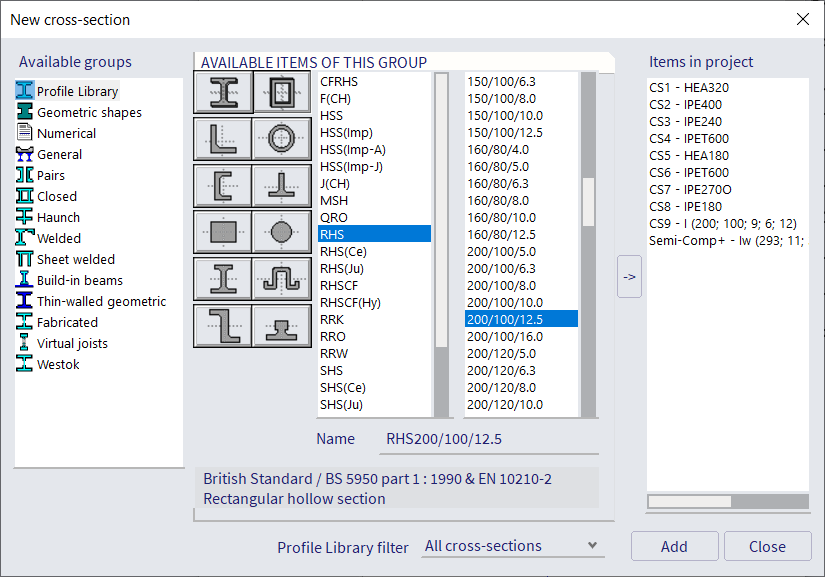
SCIA Engineer supports a variety of cross-sections, which are all supported for the steel design module. The classification can be performed on any thin-walled shape. Those sections include:
- A wide variety of symmetrical, asymmetrical, paired, or welded sections, as well as members with variable height, haunches, and stiffeners.
- Sections found in the standard Profile Library can be used, adapted, stored, or reused.
- Sections created or imported with the General Cross-section Editor module.
- Hot-rolled and sheet-welded sections can sometimes also fall under class 4; In this case, SCIA Engineer automatically derives effective sections for compression, strong- and weak-axis bending
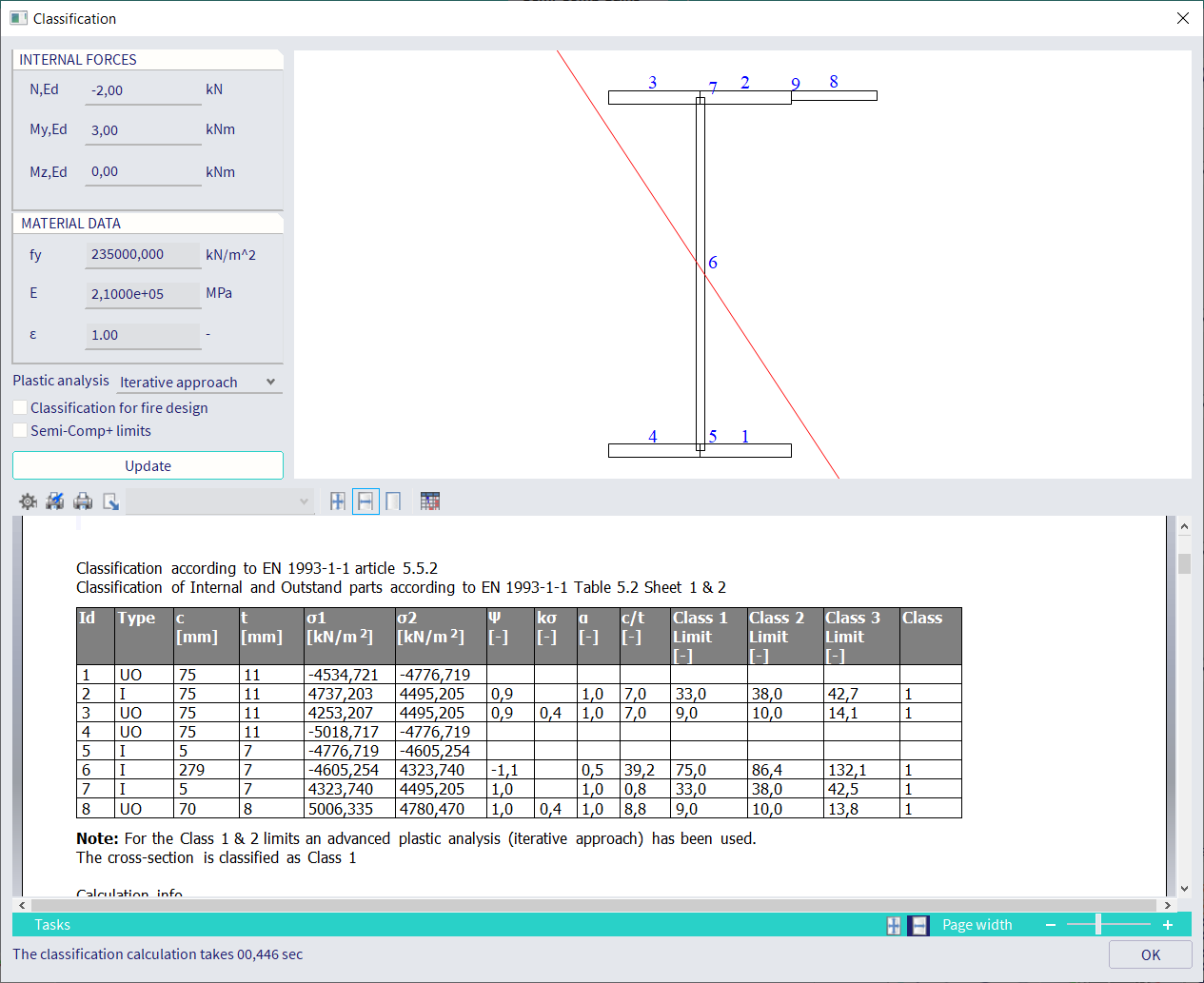
For Eurocode, AISC, and SIA codes, a standalone section classification tool allows to preview and investigate the classification of the cross-sections as well as preview the effective section and its properties for a chosen combination of loads. This same tool is used in the background while performing the checks to obtain the correct properties for the design.
SLS Design
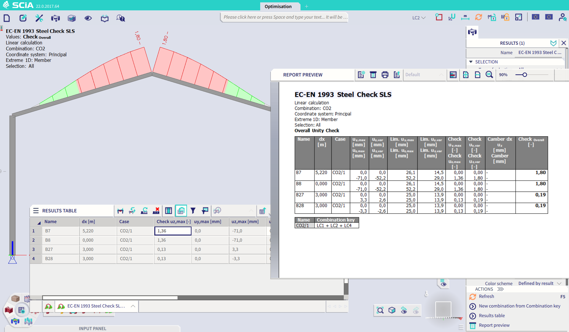
The SLS design module allows fast verifications of relative deformations together with a check or automated design of camber. The module offers:
- Simple definition of support points
- Check for total and variable loads
- Manual limit definitions, both global and member specific
- Input or design of camber
- Visual or tabulated output
Fire Design
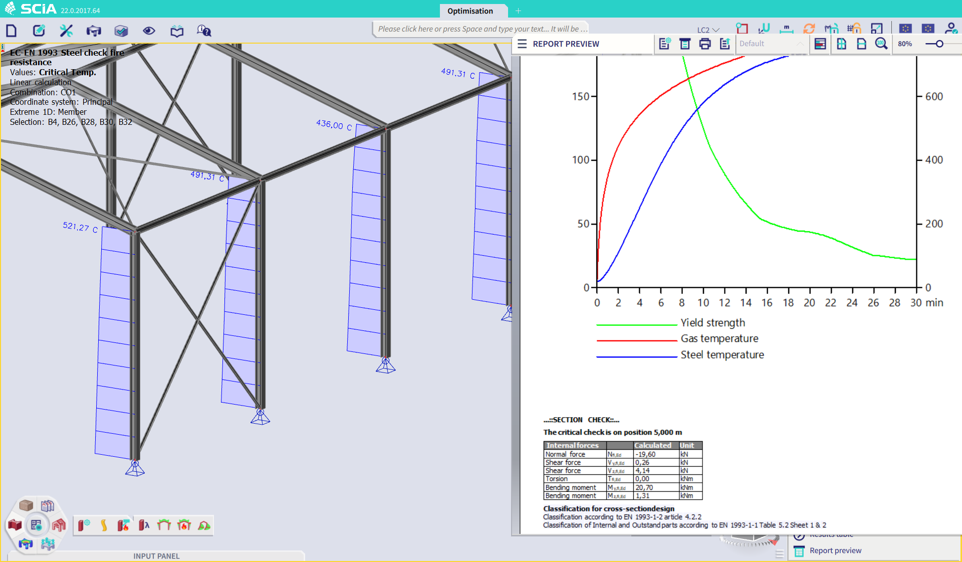
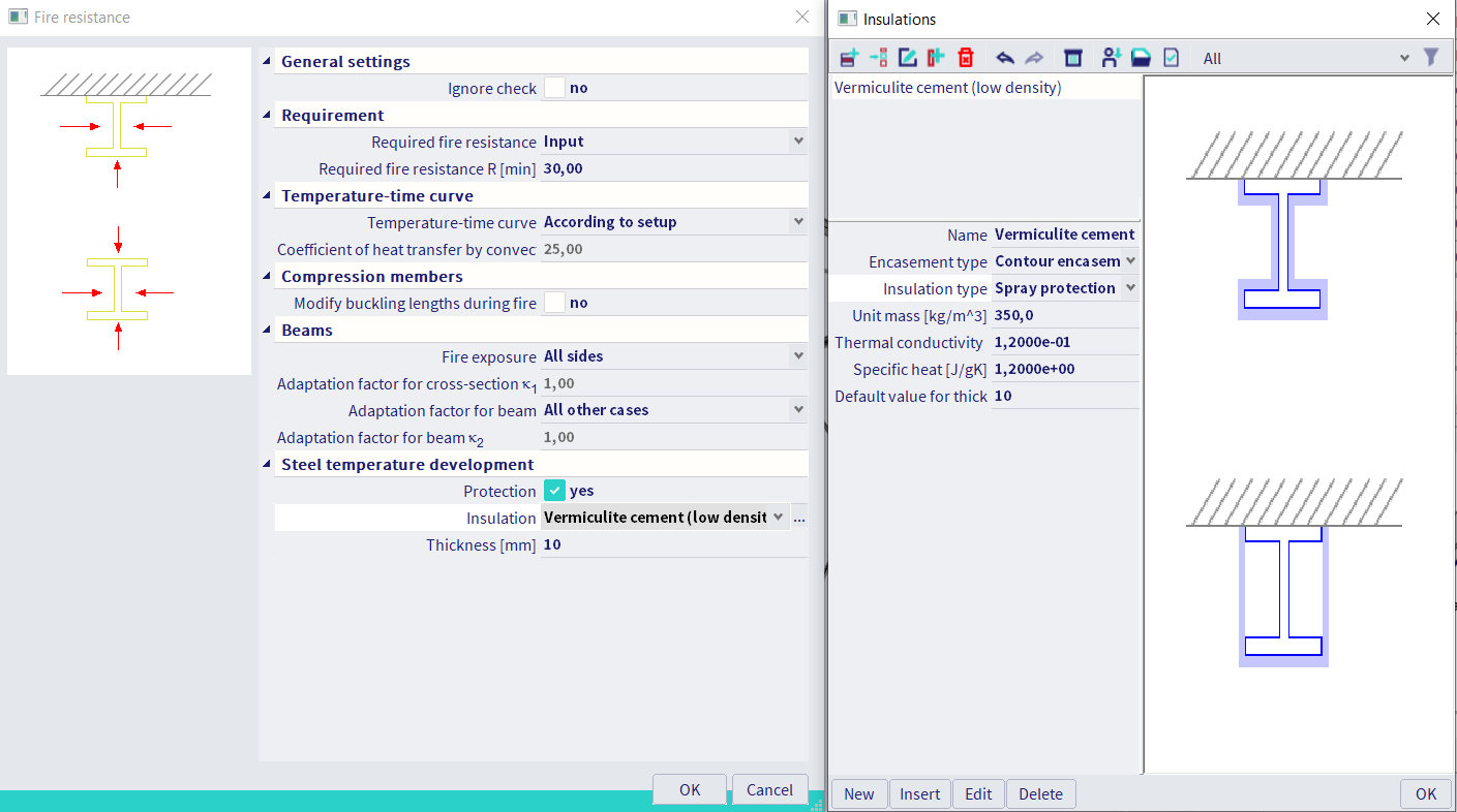
Fire situations can be designed according to EC 1993-1-2, with the same benefits and levels of output as for the ULS design. Additionally, it comes with the following options:
- Choice of standard or input of parametric temperature curves
- A library of types of heat insulation, extendable by the user
- Input of the required fire resistance for the global model or per member
- Determination of the critical temperature
- Customized exposure (3- or 4-sided), fire protection layers and consideration of shadowing effect for unprotected members
- Alternative flexural buckling length factors for the fire situation
Reporting & Output
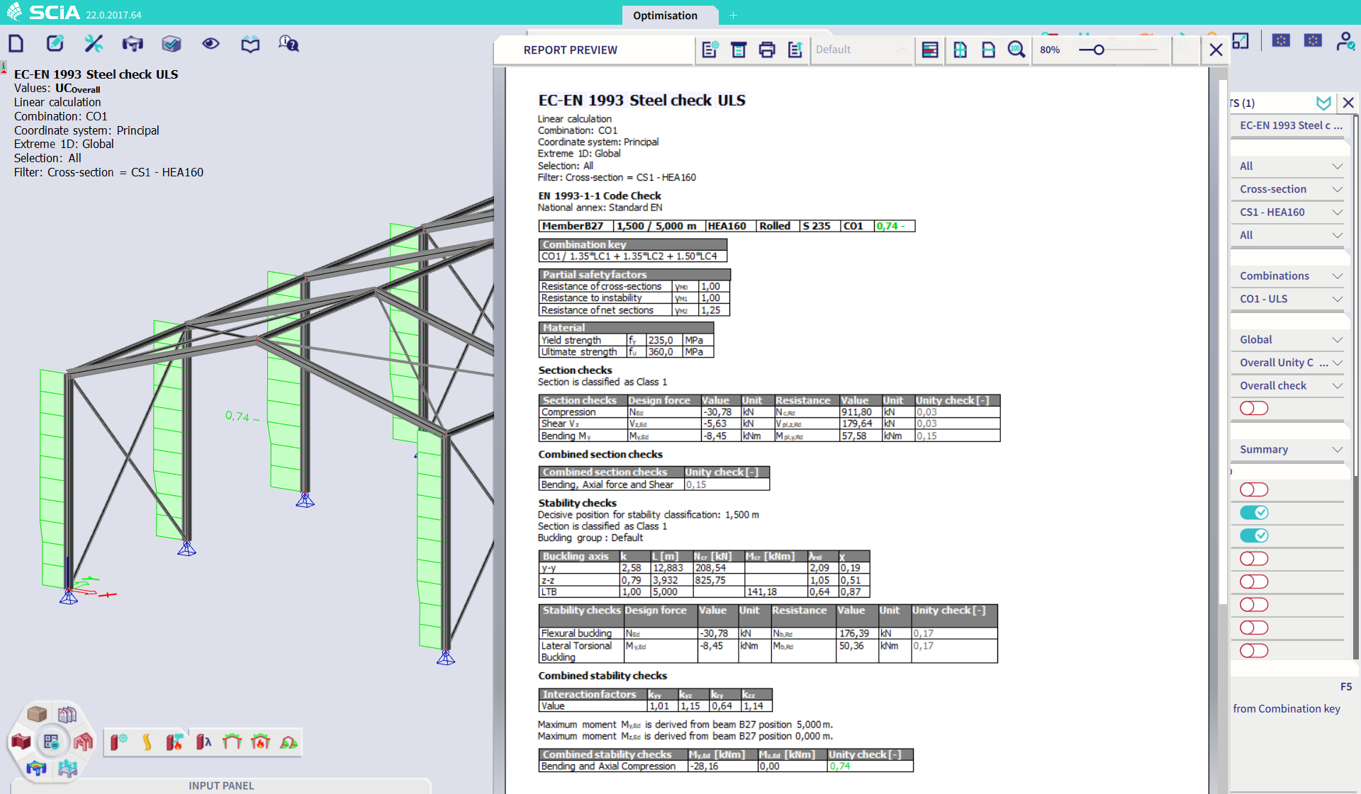
Being able to design is worth nothing with a clear way to display and report the results. The Steel Design module offers a multitude of ways to display, report and check the obtained results for the steel ULS, SLS and fire design.
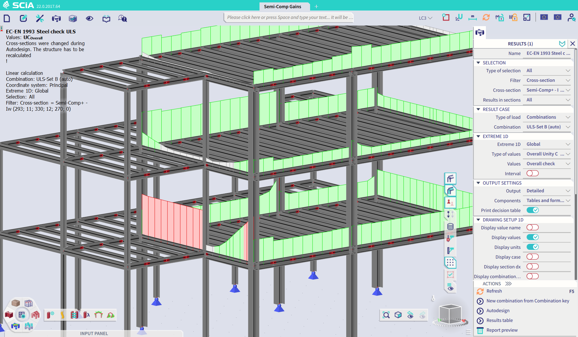
- A color-schemed display of the utilization levels on the model allows for a quick identification of the problem areas. Intermediate values, errors and notes can also be displayed on the screen.
- The design outcome for all members is easily printable in table form through the table results or brief output level.
- The summary output summarizes the important design parameters into one page, for a summarized but complete overview of the member design.
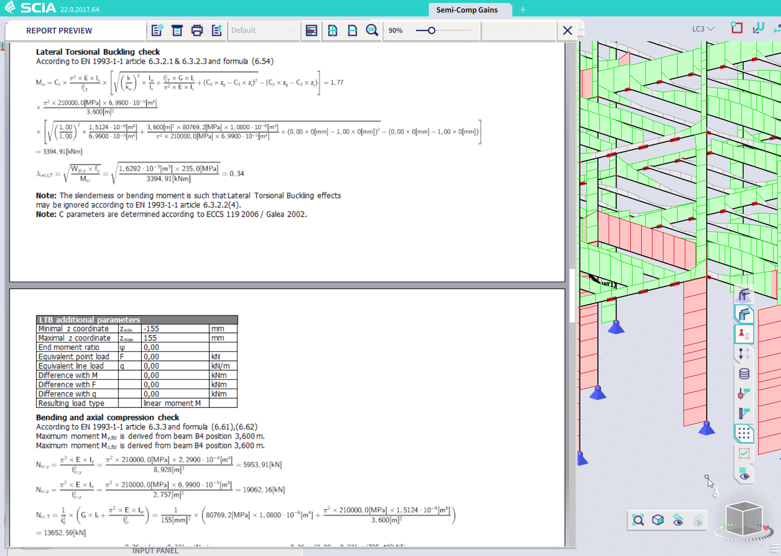
- The detailed output with tables of formula’s gives a detail of every used value and formula, together with their references for a completely transparent design.
Extensions
- In combination with the Cold-formed steel design module, the Steel design performs checks and AutoDesign of cold-formed steel members in full accordance with EN 1993-1-3.
- The Scia steel connections & drawings module allows to design steel connections according to EN 1993-1-8 and generate detailed drawings automatically
- The Advanced Material Non-linearity module includes the possibility to perform a nonlinear analysis with plastic hinges, i.e. material nonlinearity on 1D beam elements.
- Check out the SCIA Garage site for more add-ons for steel design: e.g., checks of steel plates according to EN 1993-1-6, fatigue checks according to EN 1993-1-9.

Want to try SCIA Engineer yourself?
Explore how our software and services can help you optimise your work and boost your productivity. Try it for yourself with a free 30-day software trial.
Download a free 30-days full trial