
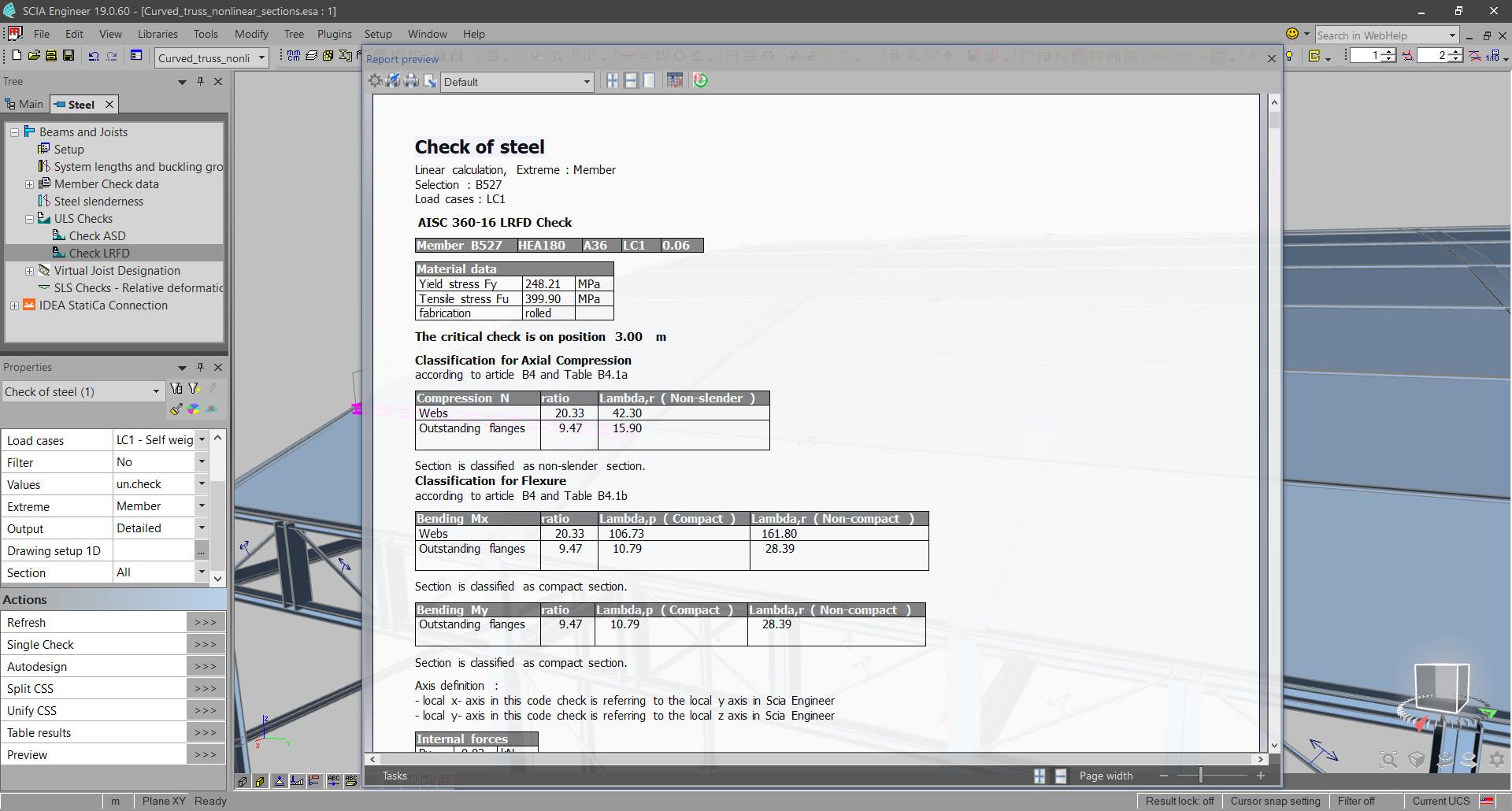
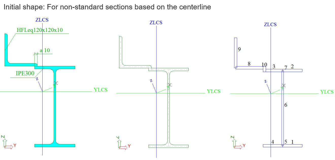
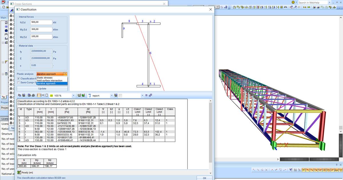
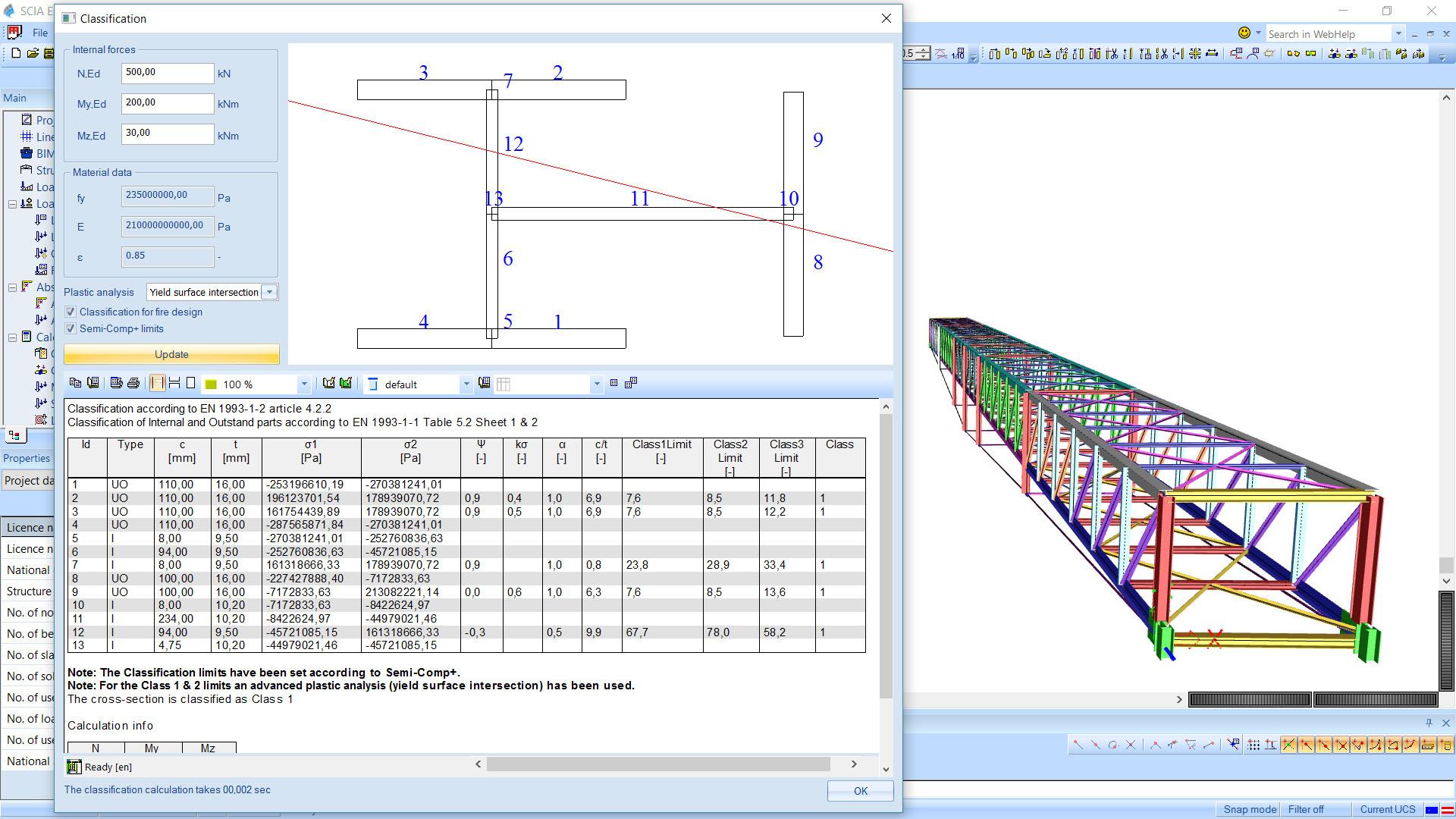
sensd.01 - Steel design

  • Module code sensd.01
  • Software
    • SCIA Engineer
  • Included in editions
    • Concept,
    • Professional,
    • Expert,
    • Ultimate
  • Category Steel Design
  • License Perpetual

Highlights

  • Correct, code-compliant design of steel members of all section classes: from the compact to the slender.
  • A semi-automatic determination of buckling lengths based on the deformation response obtained from FEM analysis.
  • ULS section and stability checks executed appropriately, depending on section shape, slenderness, analysis type (linear vs second order), presence of initial imperfections, etc.
  • SLS deflection control under both total and variable load with the possibility to define or design camber on the members.
  • Automation in both ULS and SLS design, resulting in simple and transparent workflows, material savings and user confidence especially with larger structures.

The Steel Design module offers an interactive tool for section and stability design of steel members. From section classification to interaction checks for the various load effects on a member, SCIA Engineer guides you in achieving the optimal design with minimum of manual input.

The design follows the FEM analysis; you may choose whether to take into account 2nd order deformation and imperfections on the level of analysis, or on the level of the checks. The interaction of load effects and various types of buckling are correctly handled in both cases.

ULS checks are executed according to EC3, AISC 360, SIA 263, and NBR 8800 codes. The built-in intelligence determines which articles of the code are to be applied and appropriate design equations are selected for section and stability checks based on section class, overall slenderness, etc.

Serviceability limit state checks are available for EC3 and SIA 263 codes. SLS checks on deflections ensure the integrity of separation walls, façades and other non-load-bearing elements and finishes, as well as people's comfort.

Benefits

  • Seamlessly integrated in a 3D CAE graphical environment and user interface, the Steel design lets users visually assess the outcome of design: from proportions, stresses, and deformation to utilisation.
  • A wide variety of symmetrical and asymmetrical sections are supported, as well as members with variable height, haunches, and stiffeners.
  • Steel sheeting, lateral restraints and bracing may be used to stabilise the members and improve lateral stability checks.
  • Buckling lengths may be calculated or inputted manually. The automatic determination is based on the stiffness response of the whole structure in the corresponding plane of buckling; formulas from engineering literature take into account the stiffness of the connected neighbouring elements as well.
  • The design is smoothly integrated with advanced structural analysis: 2nd order, stability, GNIA, GMNIA. For example, imperfections can be defined based on shapes obtained from stability analysis.
  • To facilitate modelling, built-in libraries are available for materials, steel profiles and roof and floor sheeting diaphragms from various regions.
  • It is possible to utilise the plastic reserve of I-sections and RHS by using the finding of the SEMI-COMP+ research.
  • Quick optimisation routines find the ideal cross-section for the span length and applied loads at hand.

Supported codes

  • sensd.01.en contains ULS and SLS design rules according to EN 1993 (part 1-1, 1-5);
  • sensd.01.sia contains ULS and SLS design rules according to SIA 263;
  • sensd.01.ibc contains ULS design rules according to AISC 360;
  • sensd.01.nbr contains ULS design rules according to NBR 8800;

SCIA Engineer supports the therein included methods, safety factors and coefficients that are of significance to structural analysis and design.

National annex support for Eurocode 3

National Annex support is available for a number of countries: Austria, Belgium, Czechia, Cypress, Denmark, Finland, France, Italy, Germany, Greece, Ireland, Luxembourg, Malaysia, The Netherlands, Norway, Poland, Romania, Singapore, Slovakia, Slovenia, Spain, Sweden, United Kingdom. The choice of methods and coefficients specific per National Annex can be reviewed or adapted.

Cross-section analysis

 Section classification is the necessary step before applying the checking rules of most steel design codes. The Steel design module performs a robust classification of a great variety of cross-section shapes.

  • The Profile Library contains a wide variety of shapes that you can directly use, or adapt, store and reuse according to your needs. Hot-rolled products can be filtered per region (European, British, American, Russian, Brazilian, Chinese, etc.). Various sheet-welded shapes are available, as well as paired sections, fabricated products from Arcelor Mittal, Westok cellular beams, and steel joists from the American Steel Joist Institute.
  • In the General Cross-section Editor (included in module sen.05), you can create any cross-section shape and use it in the analysis and structural design; if available, cross-sections can also be imported from dxf and dwg files;
  • SCIA Engineer performs the classification on any shape that can be approximated by centrelines with thickness.
  • Hot-rolled and sheet-welded sections can sometimes also fall under class 4; In this case, SCIA Engineer automatically derives effective sections for compression, strong- and weak-axis bending;

Section Classification Tool

Calculating a different section class per combination is a lot of work... if you are calculating by hand. But in an automated computation, such attention to detail can deliver a notably more cost-efficient result.

SCIA Engineer's intelligent tool for section classification analyses any section that can be approximated by centrelines and thickness and determines among the 4 categories described in EN 1993-1-1 (and EN 1993-1-2 in the case of fire design). Classification is performed inside the Steel design module and is executed at multiple locations along the beam/column/purlin per load combination.

For Eurocode 3 and SIA 263 codes, the tool can also be used in a standalone mode (called from the cross-section editing dialogue). The standalone mode is intended for testing, comparison to hand calculations, or to support students learning engineering design. But the real value of the tool is in its integration in the Steel Code Check.

For haunched and arbitrary members, the variation of section geometry along the member length is also taken into account during the classification.


Routines for plastic neutral axis

In order to apply the section classification formulas of the code, the neutral line location needs to be determined. In the case of N + My + Mz plastic interaction, this is not a straightforward task.

The Classification Tool offers the user three numerical methods for finding the neutral line. Each method offers different level of accuracy. You can tweak the balance between accuracy and speed depending on the nature of the task at hand.

The three methods explained:

  • Elastic stresses: The elastic stress distribution is used to calculate the plastic stress distribution using closed-form formulas.
  • Yield Surface Intersection: A discrete plastic (yield) surface, or a "cloud" of points is derived per cross-section. The actual internal forces are then scaled until they intersect that yield surface. The point from the discrete yield surface that lies closest to the intersection point is then used for further determination of the plastic stress distribution.
  • Iterative approach: The actual forces are increased iteratively and each time the plane of deformation is calculated. If no plane can be determined, then the yield surface has been surpassed. The algorithm then goes back one step and iterates with smaller increments. The plane of deformation of the last calculated step is used as a yield surface.

The Yield Surface Intersection method offers a very good balance between high accuracy and speed.

Steel design

Effective Section

Not only thin-walled cold-formed steel members require the use of effective section properties. Other slender beams, especially the sheet-welded ones, often fall inside the Class 4 category. Such beams offer elegant engineering solutions and efficient material use, if designed smartly.

In the Eurocode 3, SIA 263, AISC 360 codes, an effective section is derived for any class 4 steel shape - hot-rolled or welded, closed or open, library-defined or general thin-walled. You benefits from SCIA Engineer's flexibility in the design of slender steel members: these are split into flat walls and stiffeners, whose geometry is then reduced based on their slenderness and the stresses found in them.

The obtained effective sections can he displayed graphically, and all iterations of the calculation are reported in tables.

Support for SEMI-COMP+ in Eurocode 3

The valorisation project SEMI-COMP+ n° RFS2-CT-2010-00023 provided a few publications on how to achieve a more economical design for cross-sections that fall under the class 3. The Eurocode 3 specifies that these 'semi-plastic' sections should be assumed to fail in purely elastic failure. This is rather conservative, and instead, some of the plastic reserve can be utilised depending on how slender the section actually is.

Plastic reserve based on the actual section slenderness is now implemented in SCIA Engineer for double-symmetrical I-sections and RHS. Instead of a discontinuity at the transition between classes 2 and 3 (a jump from the plastic section resistance to the elastic section resistance), a gradual reduction of the plastic reserve is applied until the class 4 limit is reached. Note that Eurocode 9, SIA 263, AISC 360, and AISI S100 already prescribe this gradual transition.

The modified classification limits published in the SEMI-COMP+ research report have also been implemented in SCIA Engineer. It is important that these limits be used in the case of semi-plastic design of class 3 sections, because these limits correspond to the safety level of EC3 when the SEMI-COMP+ design rules are applied.

Design checks

The Steel design performs a comprehensive analysis of all defined or generated load combinations to find the extreme values of section and stability utilisation:

  • Built-in decision mechanisms determine which code articles are to be used, based on the geometry, internal forces, presence of sheeting and other model parameters.
  • The following section checks are performed: axial force (tension or compression), bending moments, shear forces, torsion, section warping in I-, U- and other thin-walled sections, combined checks.
  • The following stability checks are performed: flexural (Euler) buckling for axially loaded elements, torsional and torsional-flexural buckling for axially loaded elements, lateral-torsional buckling for members loaded in bending, shear buckling and effect of lateral forces for elements loaded in shear, buckling in combined bending and axial compression, critical slenderness (only prescriptive);
  • Explicit settings are available for lateral-torsional buckling - LTB restraints, buckling length, position of load (top, bottom, centre, stabilizing, destabilizing).
  • 3 analytical methods are provided for the calculation of Mcr for the LTB checks: ECCS Galea, Lopez et al, and ENV 1993-1-1 Annex F. The value can also be determined numerically by stability analysis of a shell model, or via third-party tools.
  • Interaction of load effects is taken into account on the level of both section and stability checks.
  • For Eurocode 3, the buckling of slender flanges is checked for integrated beams or 3-plate welded beams.
  • For members with variable height designed according to EC3 or SIA 263, buckling in compression is calculated based on the recommendations of the ECCS Design Manual for EN 1993-1-1. In the case of AISC 360 verifications, the method provided in the code itself is used.

Reporting

The Steel design module benefits from an interactive reporting interface, where the results of the design are easily accessible in various forms:

  • colour-coding utilisation diagrams in the 3D scene helps to quickly identify problems anywhere in the structure;
  • the design outcome for all members is easily printable in table form via the Brief report or via Table Results;
  • a Summary report per member summarised important parameters of the design and all checks on a single page;
  • a Detailed report shows all calculations as formulas (or tables, if the user prefers) with references to the used articles in the code, letting the user follow and verify the logic and steps of the design;
  • the Summary and Detailed report are directly accessible by double clicking on the rows of Table Results; in this way, the user quickly makes the connection between details of the calculation and the members visualised on the screen.
  • errors, warnings, and notes can be shown interactively by hovering on specific members in the 3D scene;
  • a detailed overview of the section classification and effective section derivations can be added to the Engineering Report as well;
  • at all times when plotting results, the selected settings (e.g., selected load combination, member names, type of calculation and extremes) are displayed via the Result Legend in the top left corner;
  • besides the overall utilisation, you can plot specific checks onto the members using the Result Components.

The benefit of these reporting features is twofold: on one hand, the design process is accelerated, and on the other hand, it is possible to create project documentation that is complete and transparent to convince any third-parties and regulatory authority about the quality and scope of the performed structural design verifications.


Extensions

  • In combination with the module sensd.02 Cold-formed steel design, the Steel design performs checks and AutoDesign of cold-formed steel members in full accordance with EN 1993-1-3 or AISI S100.
  • In combination with the module sensd.07 LTB (2nd order), FEM calculations can be performed using elements with 7 degrees of freedom per node in the Frilo BTII solver.
  • The module sens.02 includes the possibility to perform a nonlinear analysis with plastic hinges, i.e. material nonlinearity on 1D beam elements.
  • Check out the SCIA Garage site for more add-ons for steel design: e.g., checks of steel plates according to EN 1993-1-6, fatigue checks according to EN 1993-1-9.

Required modules:

  • sen.00
SCIA Engineer free trial

Want to try SCIA ENGINEER yourself?

Explore how our software and services can help you optimise your work and boost your productivity. Try it for yourself with a free 30-day software trial.

Download a free 30-days full trial  

Request an offer for SCIA Engineer

Contact support for more technical information