Highlights
- The reconsidered setting structure for serviceability checks allows for much more flexibility with fewer settings.
- More automation, e.g., in the calculation of relative deformations, in the handling boundary conditions (e.g., supported vs. cantilever pars) makes a big difference with larger structures on the level of material savings, transparency of design, and ease of use.
- Users are not constrained in how they model: spans and restraints are, either way, recognised and users may work with spans instead and visualise the direction of checks, camber, etc.
- SLS relative deflection issues are easily counteracted with camber, achieving a more economical design in terms of amount of steel.
Serviceability design criteria are important for people's comfort, as well as the integrity of separation walls, façades and other non-load-bearing elements and finishes. This is why we put an additional focus on this aspect of the design of steel members and we extended the existing check of Relative deflection with:
- checks for deflections caused by variable loads alone (in addition to the ones caused by the total load);
- a correct and automatic handling of the checks in the case of cantilever beams;
- a simplified framework of settings for the check that allows for special cases to be accommodated as well;
- support for camber on steel members, both user-inputted and designed by the software.
With these extensions, SCIA Engineer lets steel designers check and report the relevant SLS requirements and comply with the Eurocode or Swiss standard (SIA 263) on the level of serviceability.
On the level of settings
The first major improvement users will notice is on the side of inputs. The definition of design criteria has been simplified; namely, by setting four deflection limit values only, users will be able to cover the majority of design cases: the deflection limits for variable and total loads in-plane and out-of-plane are defined in the Steel Setup for the whole structure.
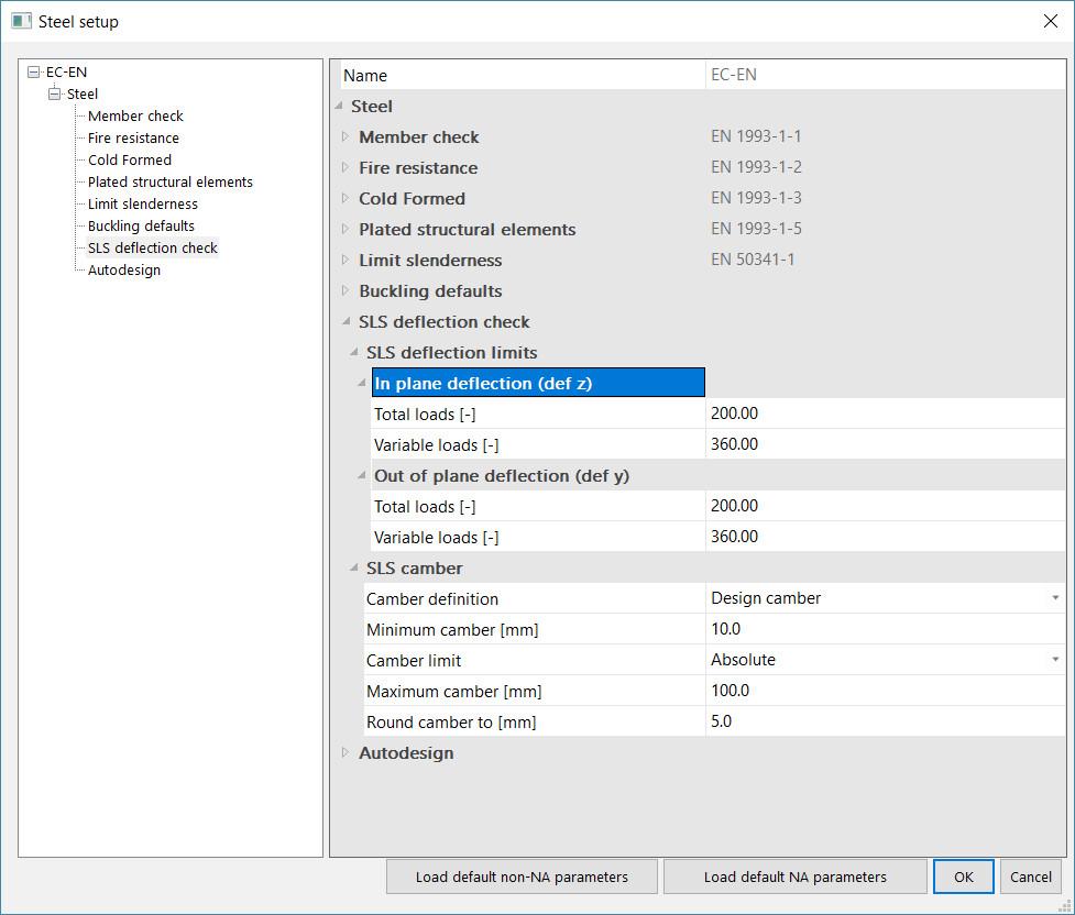
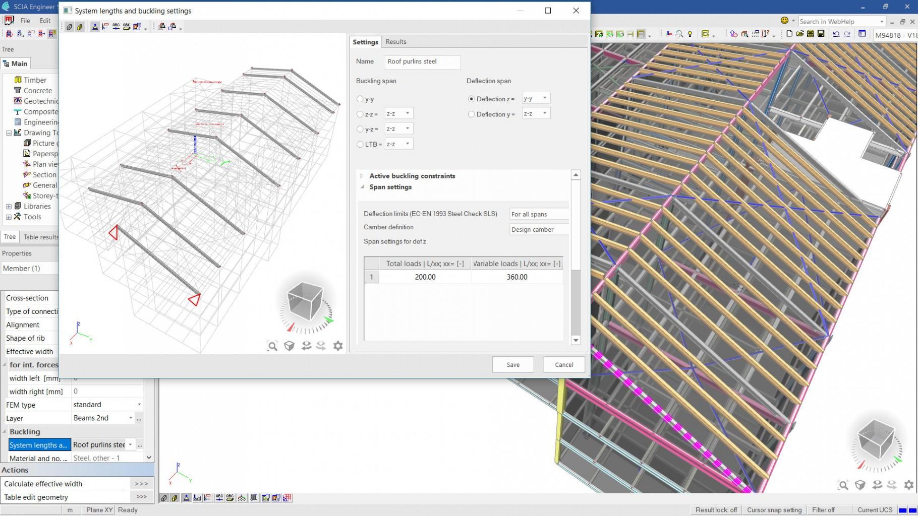
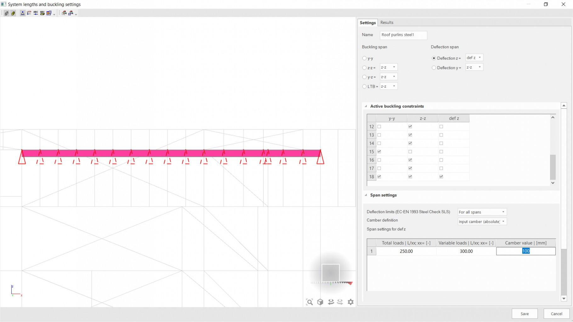
Where different deflection limits apply for different parts of the structure, these can be set via the System length settings. The advantages of using the System length framework to manage these settings are many:
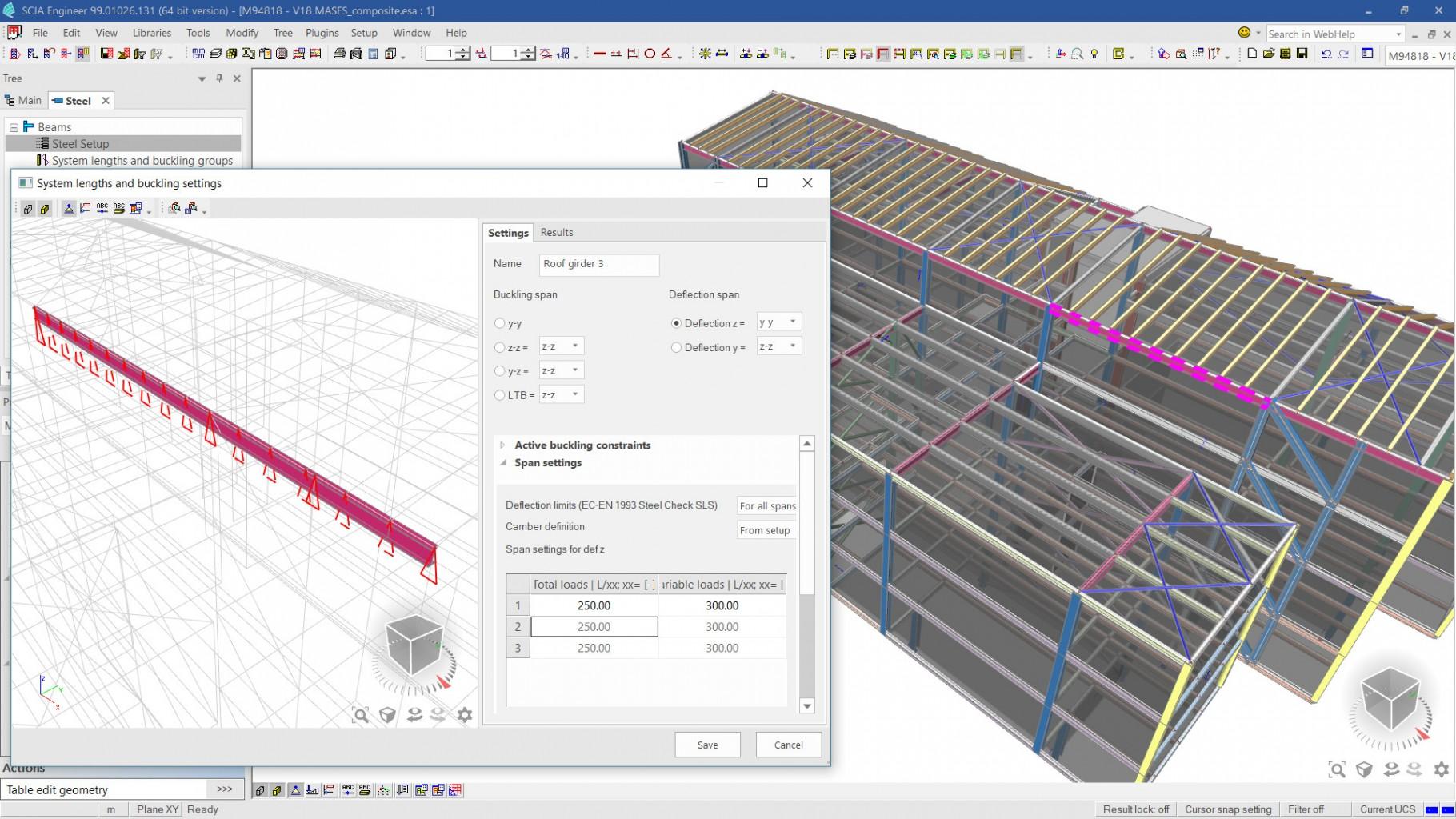
- the user does not have to model a beam per span: spans may be split, and a beam can continue over multiple spans;
- the same settings can be applied and edited for groups of members;
- the user can clearly see the direction for which settings are defined and to which members and spans these settings are relevant to.
SCIA Engineer automatically recognises spans in the majority of cases: beams, columns, bracing, walls and plates restrain other members they cross (or do not, depending on the angle at which these members cross). The System length settings let the user edit the automatically recognised restraints on similar members at the same time. These settings also define how relative deformations are calculated: at a restraint, the relative deformation is zero; along the span, the relative deformation is recalculated based on the total displacements and assumed restraints. The result are realistic deflection values that are much lower than the global displacements, especially for taller structures.
Using the automation and flexibility of these settings, users can achieve economic design solutions and handle deflection checks correctly, also in the case of complicated structures where different parts have different functions and serviceability requirements.
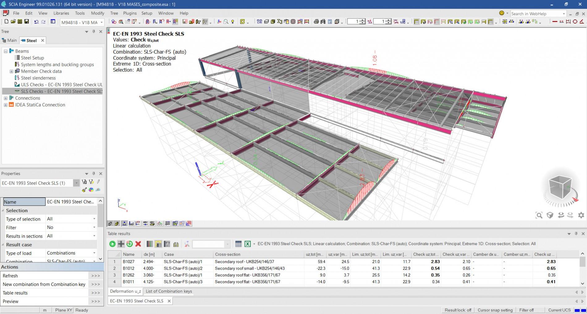
The checks themselves
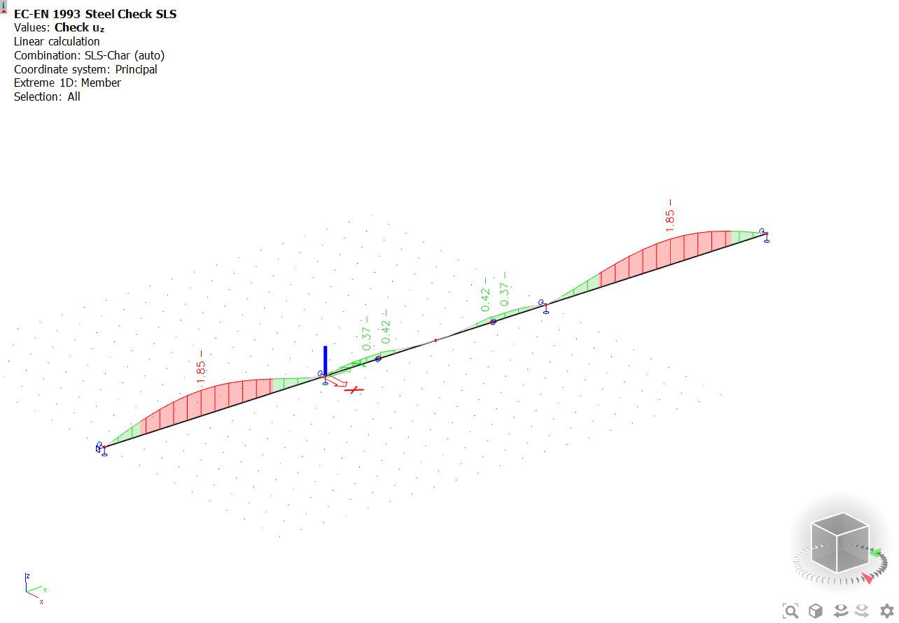
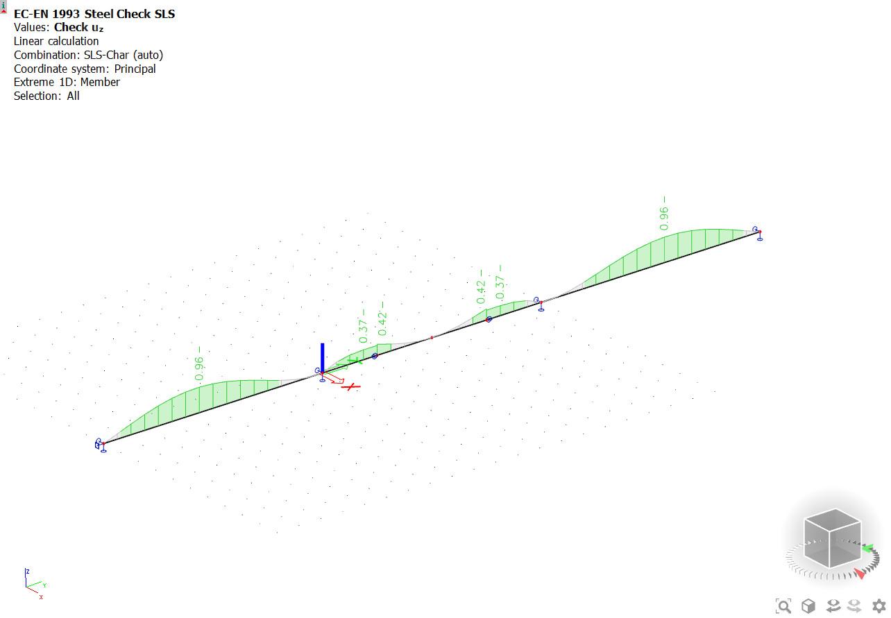
In essence, the SLS deflection checks are simple: one needs to make sure that the relative deformations remain below the limit values. The difficulty here lies in the calculation of relative deformations, and in the distinction between permanent and variable load deflections (especially in the case of nonlinear analysis results). The software handles these challenges automatically, and no action is required from the user.
The software checks deflections from the total load and from the variable load alone, in one or in two directions (in-plane and out-of-plane) if the user wishes. Reference lengths and lateral restraints are detected automatically but can be modified manually. We take into account that cantilevers beams can have double the deflection values and still fulfil serviceability criteria in terms of curvature: for cantilever spans, the deflection limits values are multiplied by 2 in the background.
These newly extended SLS checks (including camber design) are available for projects calculated according to the EuroCode or to the Swiss standards.
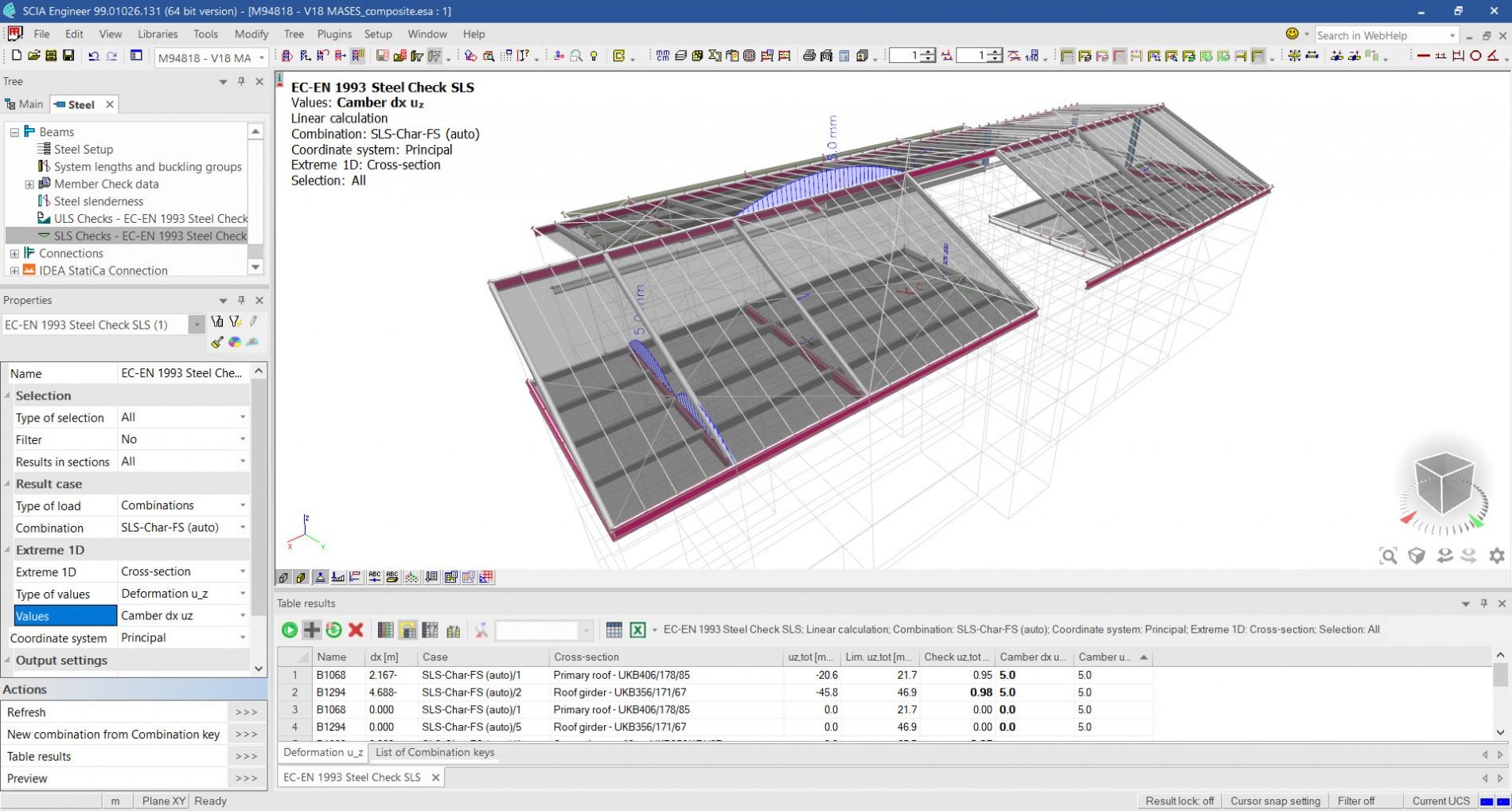
Camber
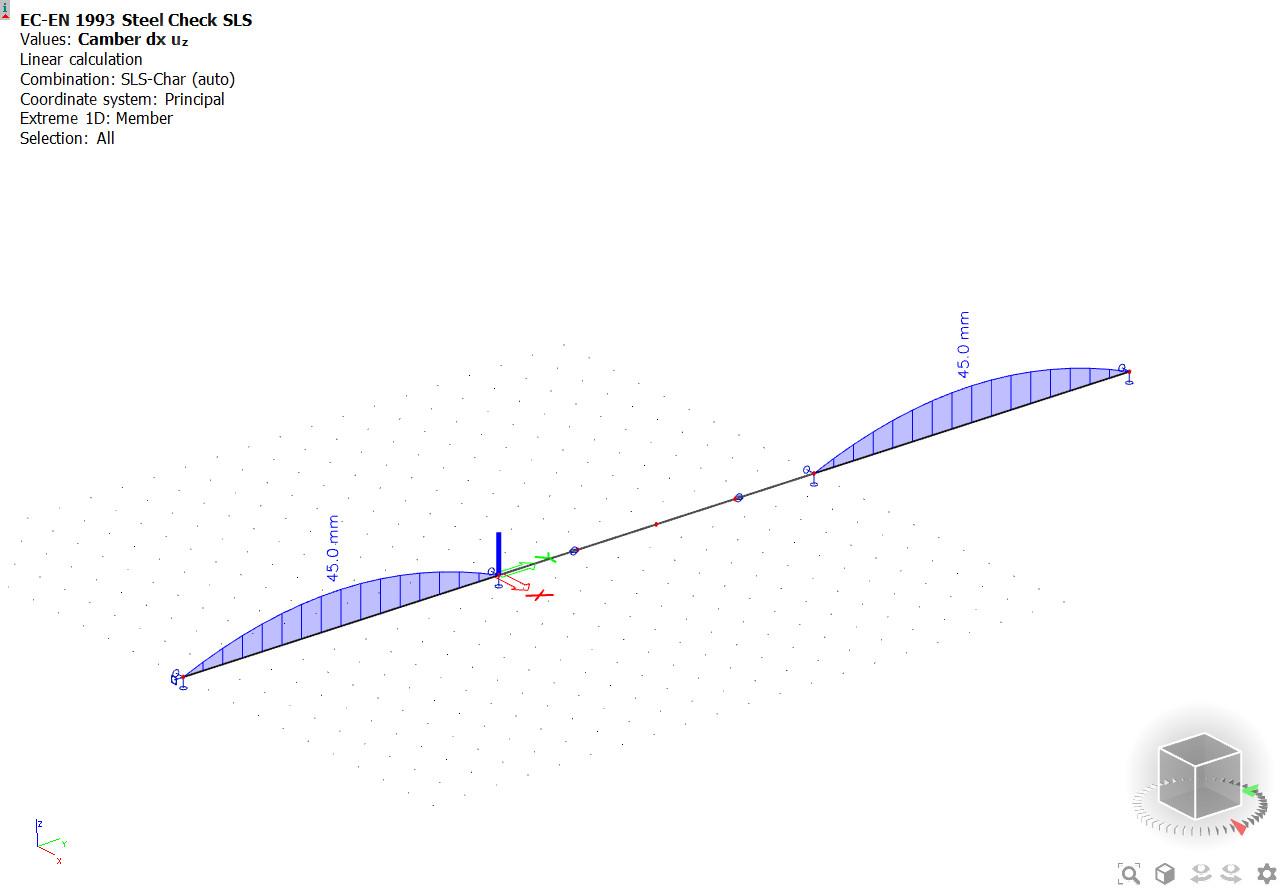
The user can specify whether camber should be foreseen on the beams for the main bending direction. If yes, he/she can input the camber values per span, or let the software determine the camber within specific production limitations.
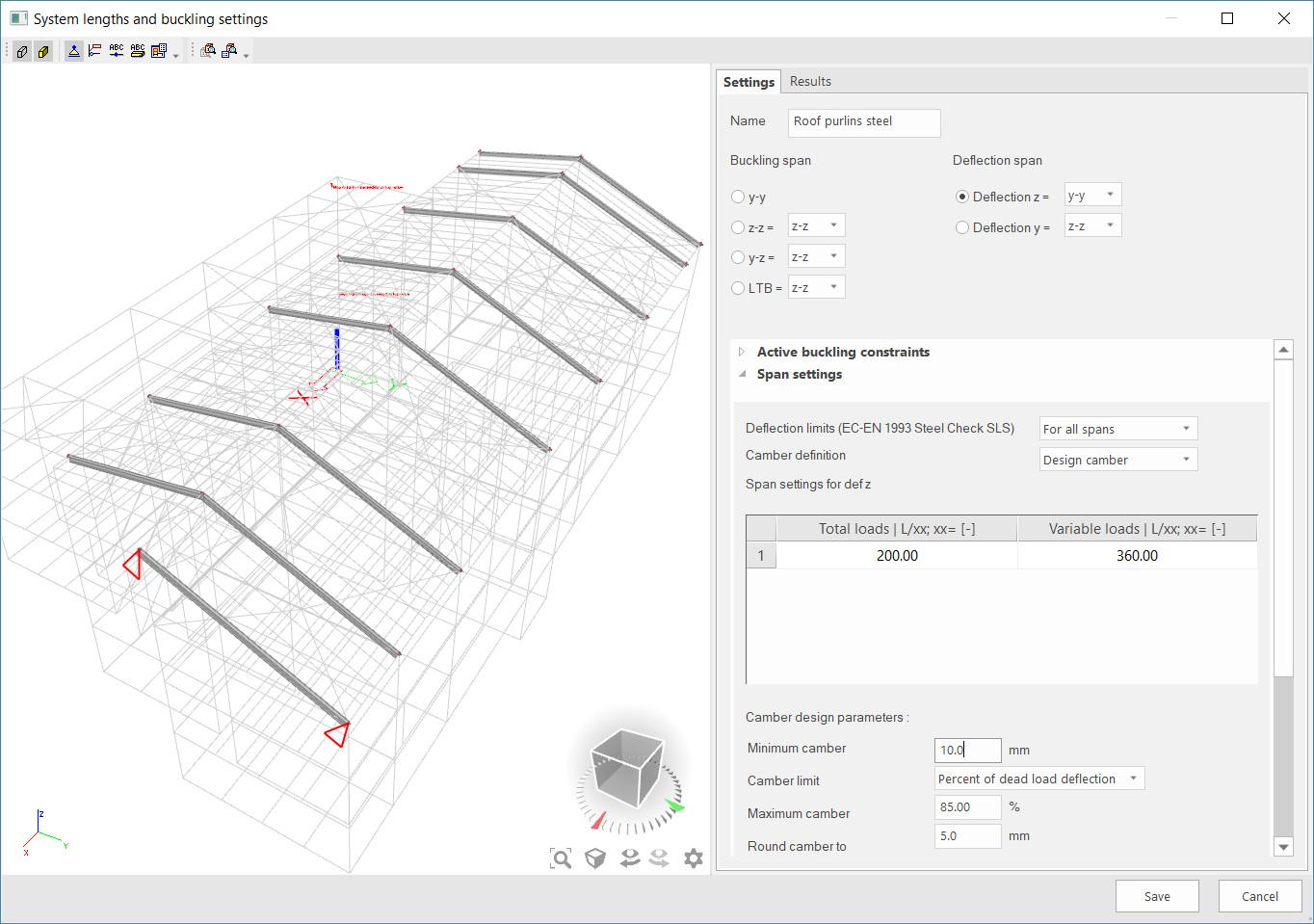
When camber is designed, the user can describe the production practice of the shop where the beams will be cambered:
- the minimal and maximal values of meaningful camber;
- precision: how should the designed camber be rounded;
- aside from the production limitations, camber can be limited to a percentage of the dead load deflection to prevent over-cambering the beams.
The cambered shape is parabolic for spans supported on two sides and linear for cantilever spans. In addition, when cambering spans that are split into multiple beams, SCIA Engineer is able to address the critical load combinations for each of the beams in the span and determine a camber value that fulfils all deformation requirements.
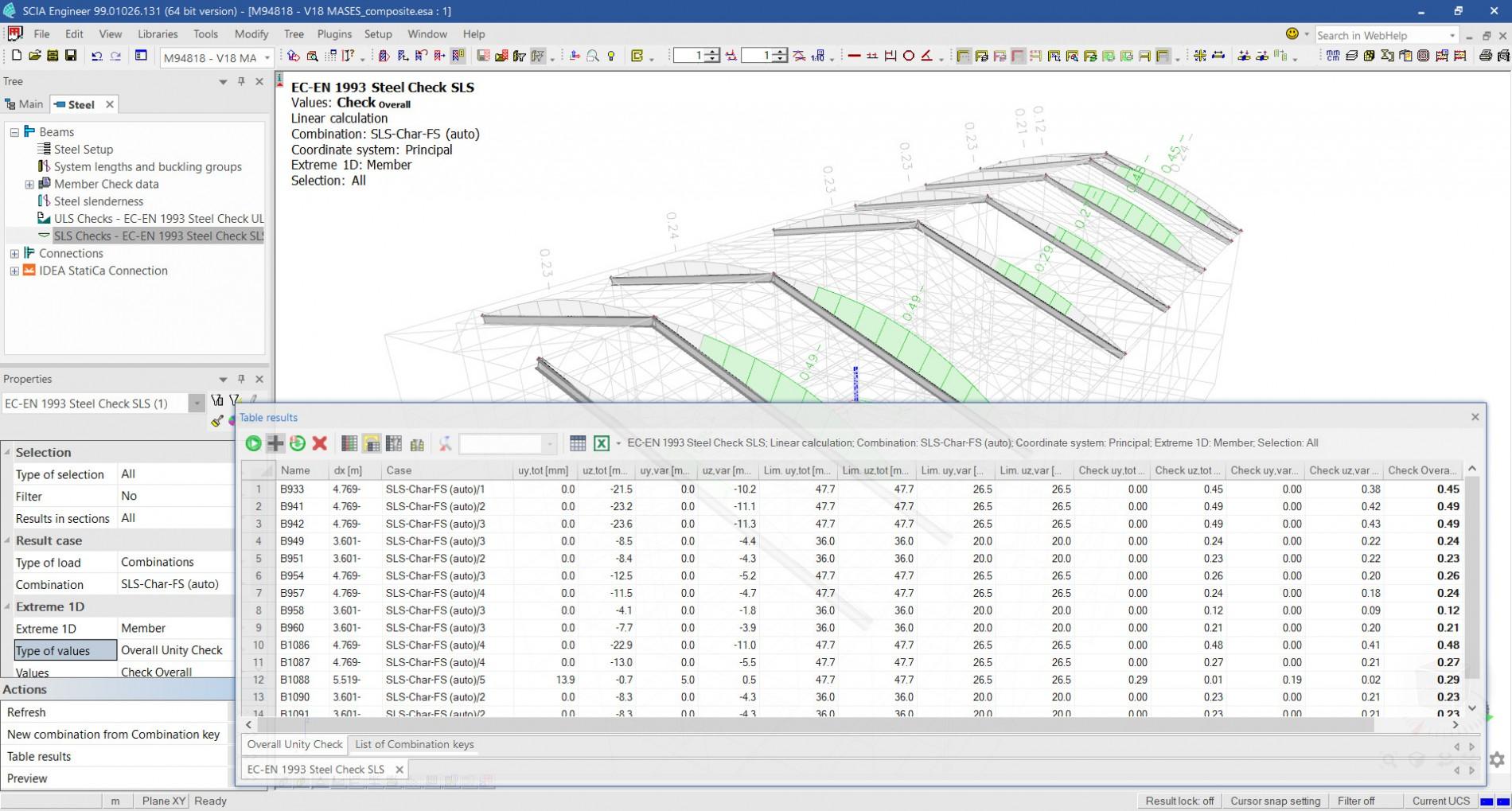
Check tools and output
The newly updated SLS checks for steel members are equipt with various tools that boost user experience:
- a link to Table Result: all result variables of the check are accessible and can be sorted there; selecting members in the 3D scene is possible directly via the table;
- EWN: the relevant errors, warnings and notes are displayed in the output, on the 3D scene, and in Table Results; such notifications let the user know if, e.g., some unusual settings have been inputted by the user.
- All result variables can be printed as separate components in the 3D scene.
The report of the SLS checks lists the relevant deflections and the load combination these result from, the deflection limits, unity checks and values of camber.
First introduced in version 19.1

Want to try SCIA Engineer yourself?
Explore how our software and services can help you optimise your work and boost your productivity. Try it for yourself with a free 30-day software trial.
Download a free 30-days full trial