Design reinforcement in slabs and walls
This FAQ explains how to use the concrete menu to design 2D elements (slabs and walls).
If you are familiar with the design of a 1D concrete element in SCIA Engineer, then you will see this part quite easily.
1. Evaluation of internal forces
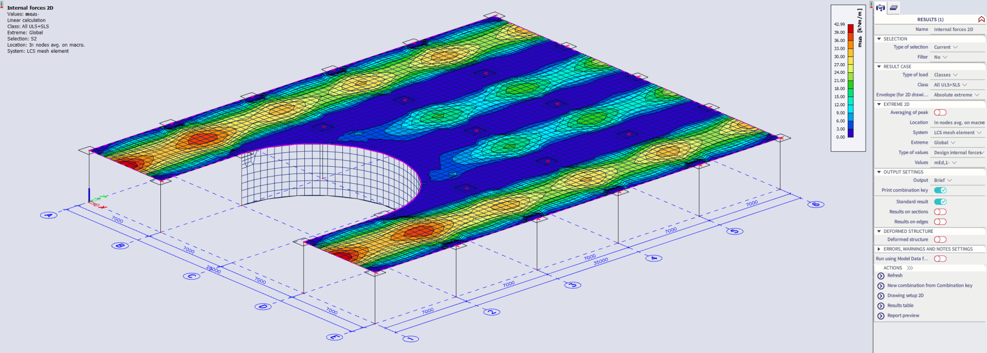
You can have a look at the internal forces so you can check if your expectations of the results are correct.
Go to Main menu > Design > Concrete 2D > Internal forces
2. Design of required reinforcement
Calculate the required reinforcement As,req to know what to define inside the template reinforcement.
You can calculate the required reinforcement As,req for the Ultimate Limit State or ULS (=As,ult). SCIA Engineer will calculate in fact two values:
- As,ult = required amount of reinforcement to resist the applied forces
- As,req = required amount of reinforcement, including the detailing provisions from Eurocode
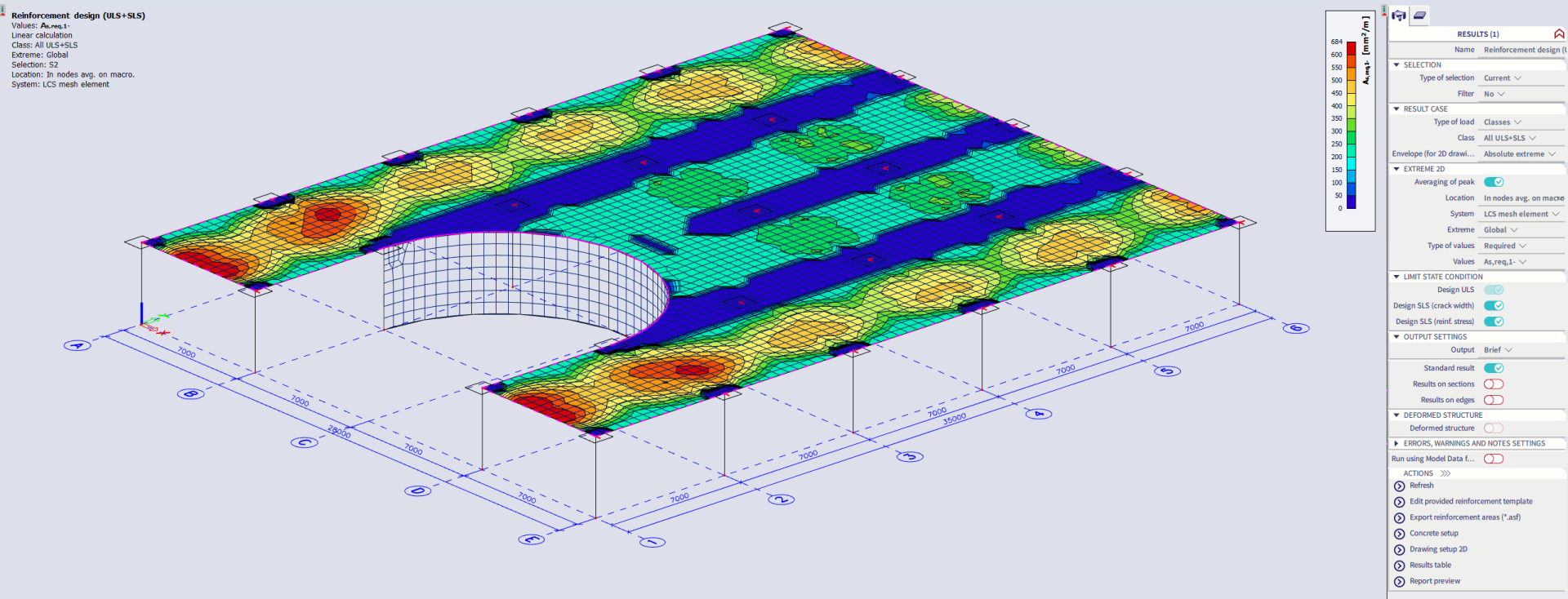
Go to Main menu > Design > Concrete 2D > ULS & SLS reinforcement
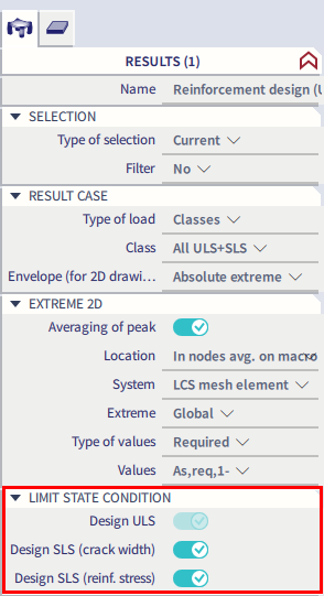
With the toggles in the Limit State Condition part of the property panel, you have the possibility as well to include the effect of the Serviceability Limit State(s) or SLS on the calculation of the longitudinal reinforcement:
- combine Design ULS with Design SLS (crack width)
- combine Design ULS with Design SLS (reinforcement stress)
- combine Design ULS with both Design SLS (crack width) and Design SLS (reinforcement stress)
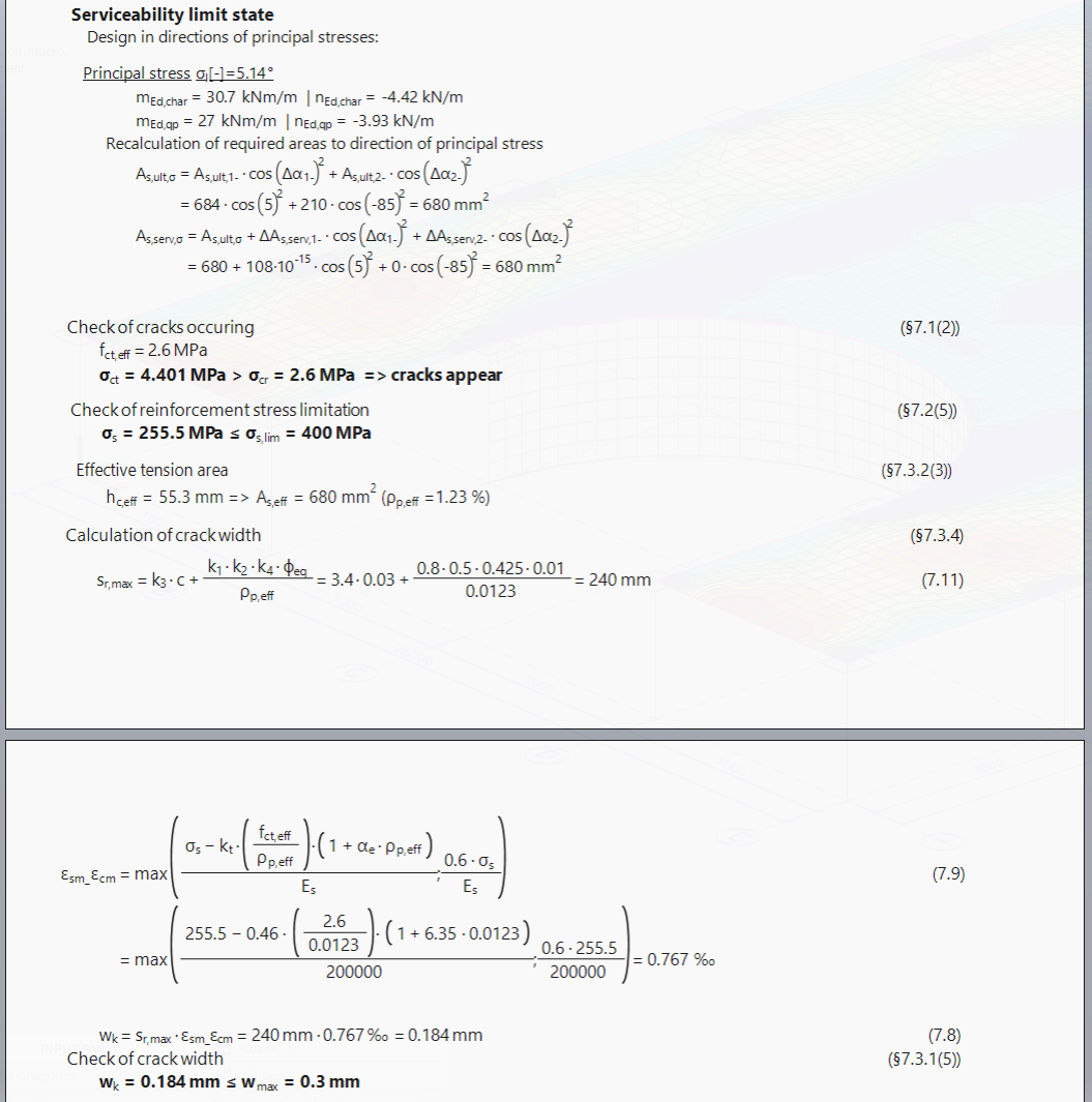
When you activate Design SLS (crack width), SCIA Engineer will calculate the required reinforcement for the ultimate limit state and use this reinforcement for the calculation of the crack width wk based on 7.3.4 of the EN 1992-1-1:2004.
To calculate the final required reinforcement following steps are executed:
- first SCIA Engineer calculates the principal forces mEd,char & mEd,qp. Therefore you need to select a result class which includes at least one ULS and one SLS combination. It makes no difference which SLS combination is there. Our smart combinator will generate all the necessary SLS combinations in the background for the calculation of the cracks and stresses.
- then a recalculation of the area of reinforcement in the direction of the principal forces is performed since in order to calculate the appearance of the crack, we need the amount of reinforcement calculated in the direction of the principal forces
- based on chapter 7.3.4 from EN1992-1-1:2004, SCIA Engineer will calculate the crack width and the software checks if the cracks are within the limits or not. If yes, then As,ult is good enough to fulfil the reinforcement for ULS + SLS (crack width). If not, then the software will start the iteration processing to increase As,ult by an extra amount of reinforcement to make the crack width within the allowable limits.
- in the output you can see it when no additional longitudinal reinforcement is needed when the value of delta As,serv is equal to zero and when the value of wk is less than the limit value.
When you activate Design SLS (reinforcement stress), SCIA Engineer will calculate the amount of reinforcement for ULS and use this reinforcement to calculate the actual stresses in the reinforcement and finally, compare that with the allowable limit which is located inside the concrete settings.
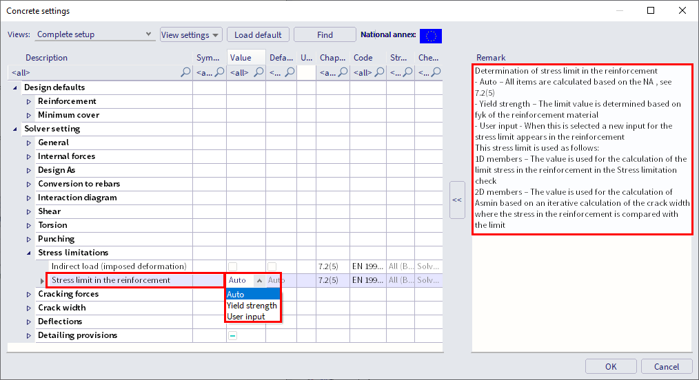
You have three possibilities to define the limit of the stresses:
- Auto = based on definition in the national annexes 7.2(5)
- Yield strength = the limit value is determined based on fyk (characteristic yield strength of the reinforcement material)
- User input = the limit value must be defined by the user
The output shows the stress limitation check:
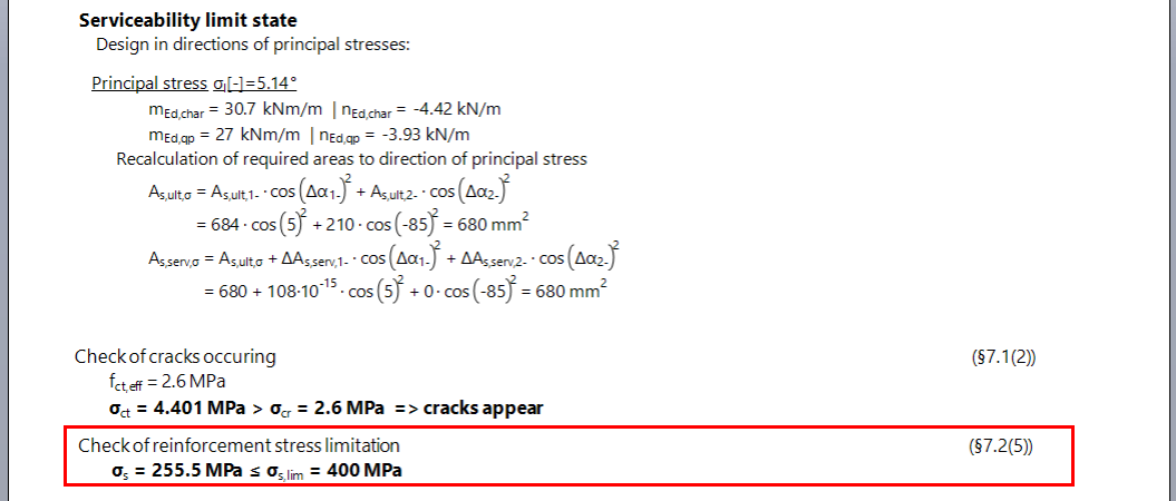
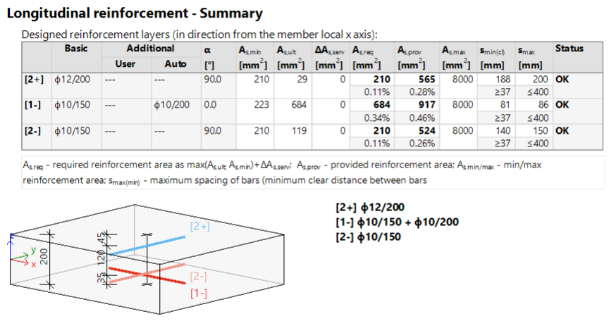
The result for the required reinforcement for both ULS and SLS design looks like:
3. Definition of a template for provided reinforcement
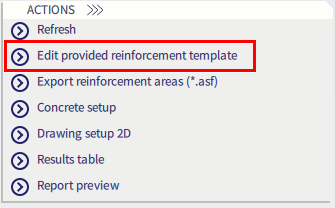
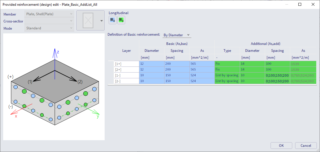
You can change the template for the provided reinforcement via Main menu > Design > Concrete settings > Settings or Reinforcement design defaults or in the property panel of the ULS & SLS reinforcement command via the action button Edit provided reinforcement template (and then select an element which has the template that you would like to change):
Based on the results of As,req you can decide the content of As,bas and As,add inside the template reinforcement. Basically, up to 50% of the max top reinforcement can be a good plan as basic reinforcement for the top side of the slab and 50-70% of the max bottom reinforcement could be a good plan for the bottom reinforcement. However, this, of course, depends on many factors like the geometry and the support condition.
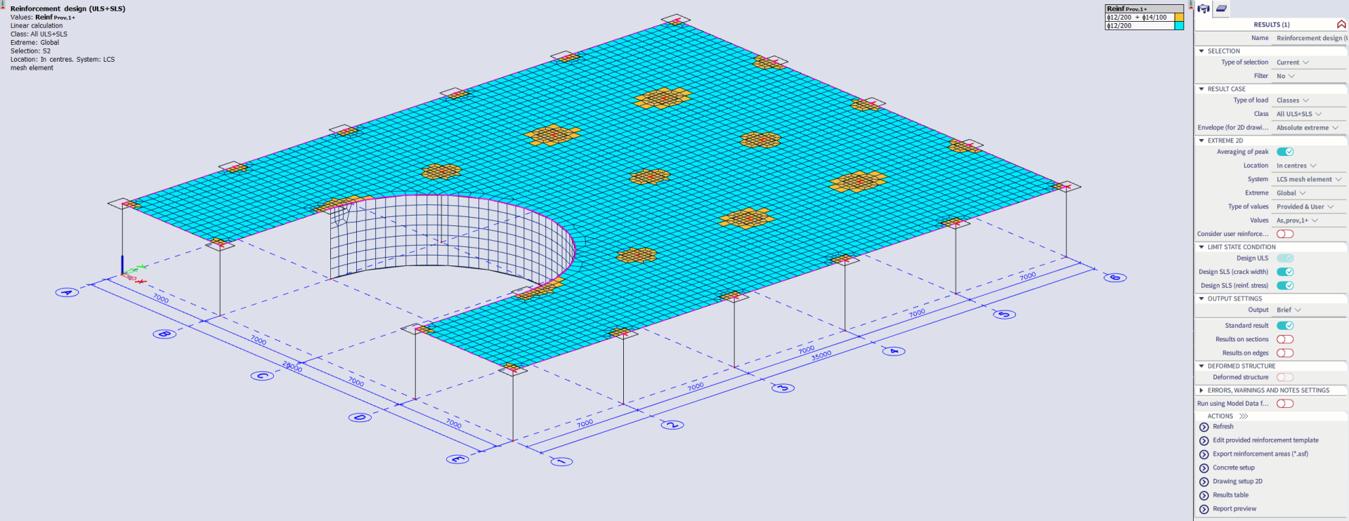
4. Design of provided reinforcement
In this step, the final results will be a combination between the basic amount of reinforcement to cover the whole slab and the additional reinforcement As,add which is only to cover the critical parts of the slab where As,bas is not enough.
Generate your final result:
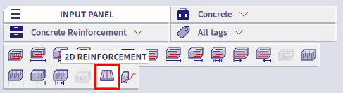
It is possible that the settings in the template are not sufficient to take all forces. Then you need to increase the additional reinforcement in the template or you can add manually user reinforcement at the desired locations (via Input panel > workstation Concrete > category Concrete Reinforcement > 2D Reinforcement):
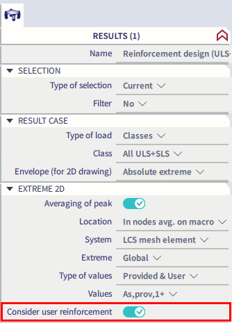
In this second case, activate the toggle Consider user reinforcement when you execute the ULS & SLS reinforcement command, so this user reinforcement is taken into account as well!
Afterwards you can perform the necessary checks, such as Code Dependent Deflection.