Modeling Isokorb component
Isokorbs are special components used for the reduction of thermal bridges in concrete structures. This module is applied especially in case of a connected balcony with a reinforced concrete deck. When such a detail is designed, an appropriate numerical model needs to be considered. Within this article, several methods using FEM calculation in SCIA Engineer are described.
Model definition
Schöck Isokorb is a special component which consists of bent up reinforced bars transmitting the tension in the detail and HTE-compact material bearing the pressure. The insulation gap between the structure and the balcony is filled out by hard foam polystyrene. This component is able to transfer bending moments and shear forces depending on the selected produced model type. Torsional moments however cannot be transferred at all. The transfer of internal forces depends on the established component stiffness.
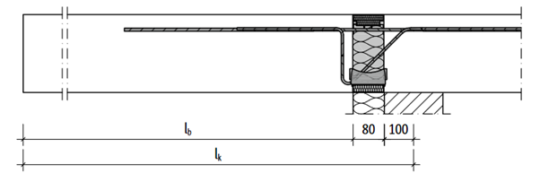
Generally, there are three options for how to correctly make a model with Isokorb in SCIA Engineer:
- 1) Separate the balcony part from the model and apply the resulting reactions to the building concrete deck
- 2) Usage of a line hinge with appropriate stiffness
- 3) Usage of a nonlinear contact hinge
Isokorb recommandation
Technical information [1] according to EN1992-1-1 [2] for Isokorb® includes a FEM guideline describing the modelling. The Schöck company recommends the following approach for the design of Schöck Isokorb® using the finite element method:
- Separate the external component from the supporting structure of the building.
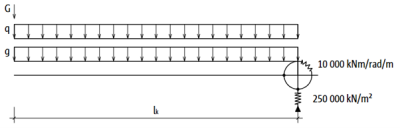
- Determine the internal forces on the external component support, taking into account the spring stiffness values using the following recommended approximate spring values for Schöck Isokorb®:
- 10 MNm/rad/m for a rotational spring
- 250 MN/m² for a vertical spring
- Select the Schöck Isokorb® type, including the determined design values for the shear force vEd and the moment mEd.
- Apply the calculated shear force vEd and the moments mEd as external edge loads to the load-bearing structure (ceiling slab, for example).

Case study
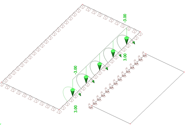
The modelling and comparison of the result is demonstrated on a 250 mm thick slab with dimensions 3,0x6,0 m from concrete C25/30 which is joined by a balcony with the same material and thickness with dimensions 2,0x4,0 m. A uniform permanent load of 1,0 kN/m2 and a variable load of 1,5 kN/m2 are applied on the whole structure.
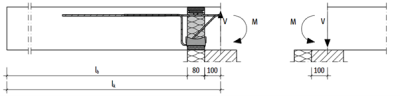
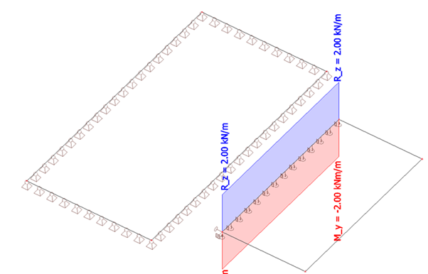
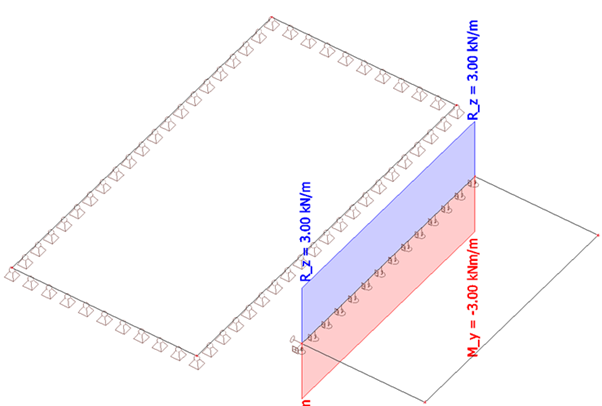
Method 1 - Separate balcony part from the model and apply the resulting reactions to the building concrete deck
The first method is based on splitting the balcony from the rest of the structure and making the proper support definition on the connecting edge. Based on the obtained reaction the load is applied with opposite sign to the rest of the structure. The stiffnesses of the support are visible on the following figure.
Note: The determination of the reaction from the balcony and the load redefinition to the master deck must be done per load case independently
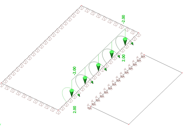
The reactions in the balcony are then determined and applied on the deck.
Load case - permanent
Load case – variable
As can be seen, this method is quite labor-intensive since it requires manual input during the reading of the reactions and redefinition of the load to the slab. Therefore, the next, more efficient, method is evaluated.
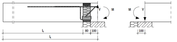
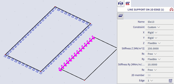
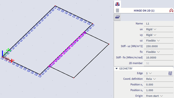
Method 2 - Usage of a line hinge with appropriate stiffness
The more user-friendly approach on how to define the real behaviour of IsoKorb is the usage of a line hinge with special properties in one common model. The linear hinge is defined on the balcony edge with the following recommended properties. Flexible stiffnesses for both the shear force (uz) and bending moment (fix) transfer are used.
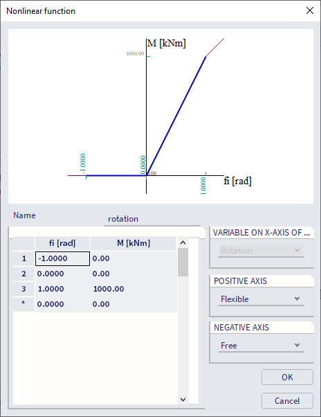
Method 3 -Usage of a nonlinear contact hinge
The previous methods are based on a linear analysis. The third method uses so-called “contacts” which are in fact nonlinear function of the line hinge.
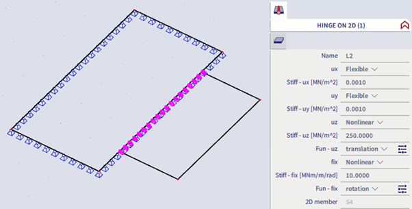
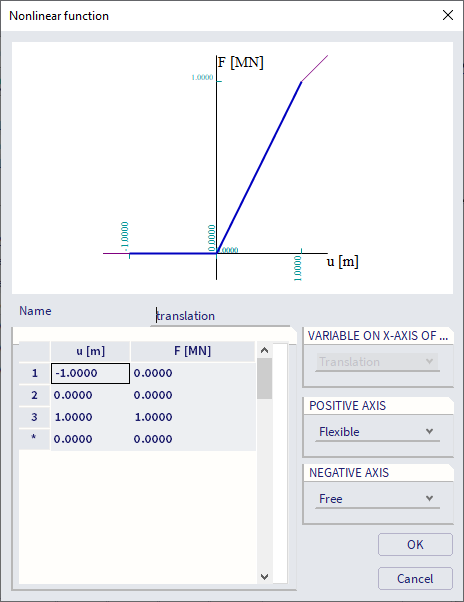
Based on the preconditions, the nonlinear functions for vertical translation and rotation are defined as follows. As illustrated on the picture, the hinge behaves differently in compression and tension. There is in fact no transfer of the compressive load and the tensile load behaves linearly. Additionally for this method it’s necessary to define a nonlinear combination and run the nonlinear calculation to get the results based on these nonlinear functions (left below: nonlinear function of translation, right below: nonlinear function of rotation).
Results discussion
On the following figures the results of all three methods are compared. At first, the bending moments of the structure are checked. The evaluation of the bending moments is almost the same for all three methods as can be seen on the following figure in case of linear analysis.
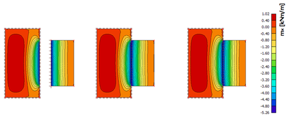
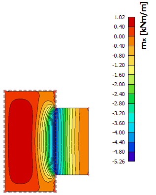
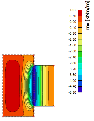
Additionally, the difference between the linear and nonlinear method is also very small from the point of the bending moments as shown below (left below: linear result, right below: nonlinear result).
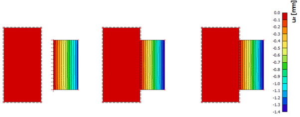
Also in case of deflections there is a good correlation for the linear analysis (see below).
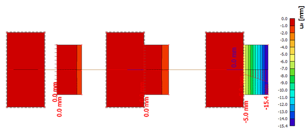
But when comparing the results after nonlinear analysis, high deflections can be seen for the third method due to the absence of the real reinforcement definition during nonlinear analysis which will have a significant impact to the deflection in this case.
Conclusions
Three possible methods of modelling Isokorb were demonstrated in this article. As illustrated, all three methods can be used but with different modelling effort. The first method required a manual redefinition of the reaction values from the free balcony to the master slab which could lead to mistakes. The third nonlinear method requires the definition of real reinforcement in the structure to obtain the correct deflection of the balcony. The second method is therefore a good compromise by using a linear hinge with recommended stiffness values which provides good results with a small effort of modelling.
Reference
[1] Schoeck Isokorb - Technical Information; https://www.schoeck.com/view/2664/Technical_Information_Schoeck_Isokorb_%5B2664%5D.pdf
[2] EN1992-1-1 - Eurocode 2: Design of concrete structures - Part 1-1: General rules and rules for buildings