IFC to SCIA analytical model using import and BIM toolbox
SCIA Engineer easily plugs into any workflow, reducing manual tasks and adaptations, while making a project and collaboration among the project stakeholders more effective. The IFC format, one among many that SCIA Engineer supports, is a foundational element enabling Open BIM. SCIA Engineer is the first structural analysis software certified for both IFC 2x3 import and export. The application features the unique BIM toolbox that helps to optimize the Open BIM workflow for structural analysis.
Note: This workflow can be done even more efficiently using the SCIA Autoconverter.
IFC import of a model
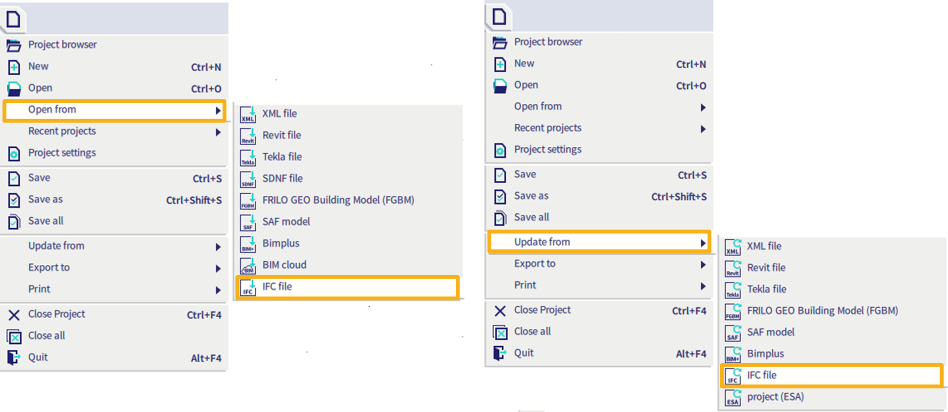
The IFC import (or update) can be run from Main menu > File > Open from > IFC2x3. This function supports both plain IFC and IFCzip files.
After the required IFC file is selected, the IFC import option dialog is displayed.
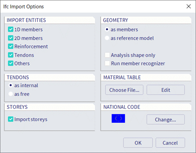
In the dialog, select what object types need to be imported (e.g. only 1D or 2D member or reinforcement,...). If the file contains also tendons, you have to select how you want them to be imported: as internal or free tendons. By default, storeys are imported from the IFC file. You can decide to ignore them by unselecting the option.
The most important option in the dialog is how you want all objects to be imported, either as native members (if possible) or as reference objects/general solids (reference model).
If the IFC file contains many objects stored with the boundary representation (BREP), it is recommended to select the Run member recognizer option, which automatically starts the Member Recognizer immediately after the import. It converts all members defined in the IFC file as beam, column, standard wall or slab to native SCIA Engineer members.
During the import, material names from the file are automatically mapped to SCIA Engineer materials using the predefined mapping table. It is important to ensure that the exact names specified in the selected national code are used.
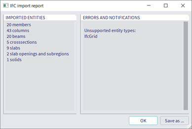
Once the import is completed, a report is displayed, showing the total number of imported elements as well as elements that were not imported.
For more information about the IFC import, please refer to SCIA Engineer help.
Creating an analytical model using the BIM toolbox
Once the architectural (structural) model is imported from the IFC file, create the corresponding analytical model using the BIM toolbox in SCIA Engineer.
After the import, member axes and midplanes are not connected to each other and some elements could have been imported as general solids instead of native 1D or 2D SCIA Engineer members (elements). Follow the next steps to create the analytical model.
Convert general solids into SCIA Engineer members
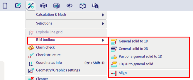
First, convert the non-native elements into native ones. Go to Main menu > Tools > BIM toolbox and start one of the convert functions: General solid to 1D, General solid to 2D, Part of a general solid to 1D or 1D/2D to general solid.
Here are the frequently used options for converting general solids into SCIA Engineer’s 1D and 2D members:
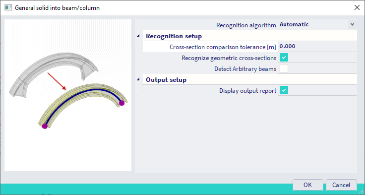
- General solid to 1D: this function creates SCIA Engineer native members from the general solids. It automatically recognizes basic cross-section shapes, member orientation (vertical columns and horizontal/inclined beams) and creates local member axes. It also handles curved beams, arbitrary beams or members with haunches. This function can be run solid by solid, or for a large number of solids at a time depending on the selection.
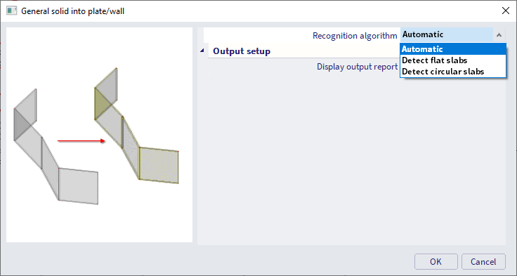
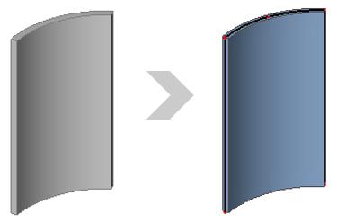
- General solid to 2D: this function automatically creates mid-planes of 2D members. Vertical elements are recognized as walls. If the wall is curved, there is an option 'Detect circular slabs' for creating a circular wall (see the example below). This function can also be run solid by solid, or for a selection of multiple objects.
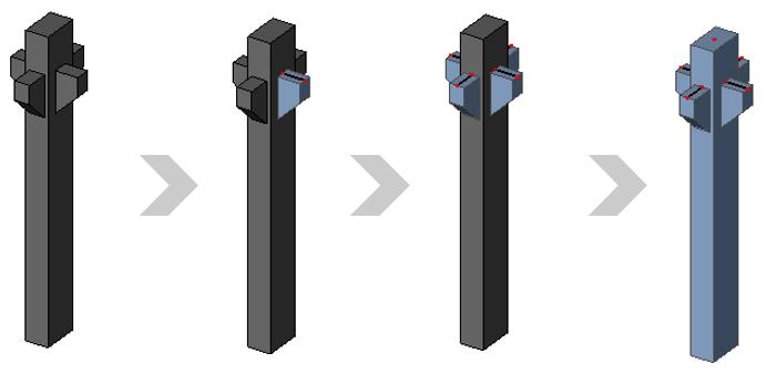
- Part of a general solid to 1D: this function is intended primarily to import of volumes with a complex shape. Each sub-part of the solid can then be converted to a beam or a surface. In the example below, a column with corbels, the corbels are converted to individual beams.
Align
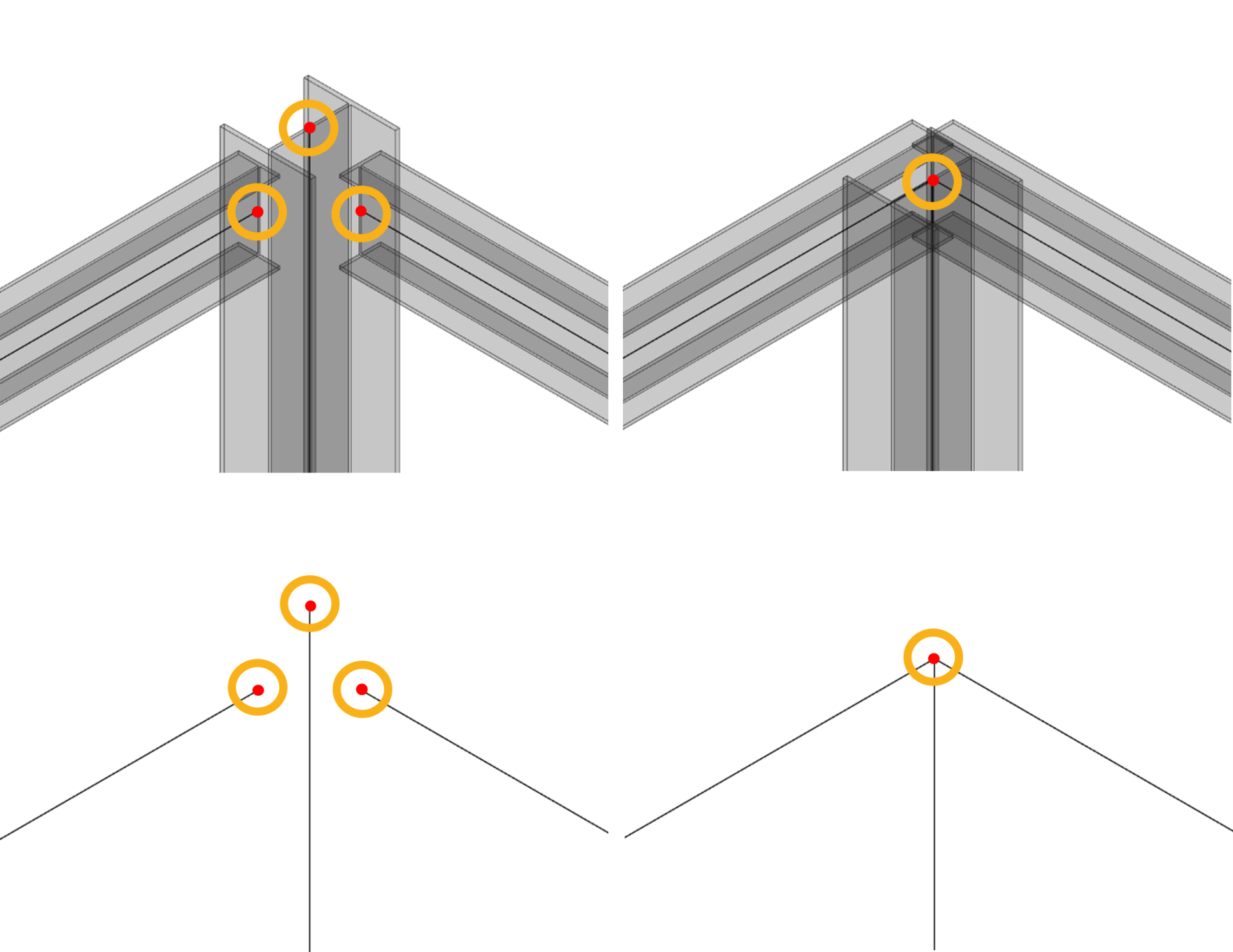
When all entities are converted to SCIA Engineer native members, their axes and midplanes must be aligned using the Align function. This is because the outer surfaces are usually perfectly aligned in the imported architectural model while the midplanes are not.
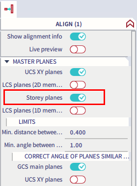
There are several options for how to align the analytical model. For example, it can be done by storeys or Local Coordinate System (LCS) planes. It is also possible to align only a certain type of members, e.g. beams to columns, columns to plates, and others. Before the function is executed, you can display a live preview.
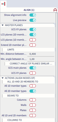
There are several ways for aligning midplanes and creating the analytical model. Below you will find a few tips how do it.
Max. node to master plane distance and Max. total displacement of node are very important options. It is recommended to start with a rather smaller distance than with a larger one to ensure that members are aligned to the expected planes.
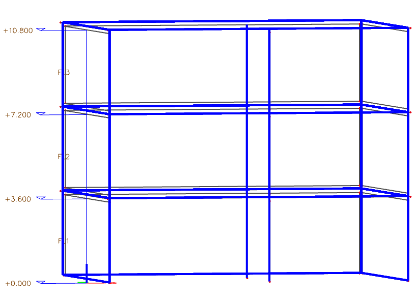
See the example in which the Max. node-to-master plane distance is set to 0.1 m and 0.15 m, respectively.
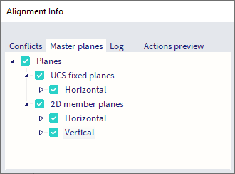
In both cases, the master planes are the same:

The result for 0.1m is:

The walls are aligned together, and the slab edges are aligned to the walls planes.
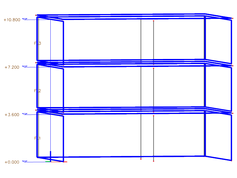
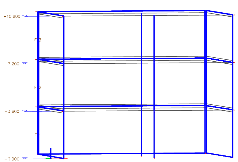
Whereas for 0.15 m, the walls and columns are also aligned to storeys:
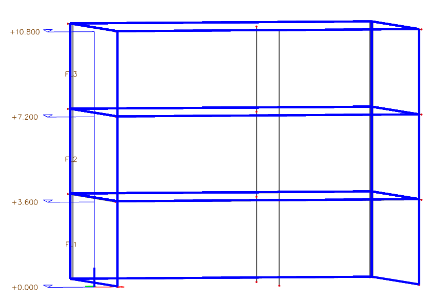
Alternatively, you can align all the elements to storey planes:
And then align the walls together (with Master planes set to LCS planes (2D members) and Max. node-to-master plane distance set as default = 0.51m) :
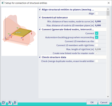
Connect
Structures are aligned by moving nodes, which means there can still be duplicate nodes present. Therefore it's necessary to check the structure data. The members also need to be connected using the connect members/nodes command. Alternatively, it's possible to connect beams to plates as ribs or member nodes via rigid arms.
In the previous example, the columns are connected to the slabs.

For more information about the BIM toolbox, please refer to SCIA Engineer help.