Crane Loads
On the 32 bits version (old interface), there is a semi-automatization with the « Mobile loads » functionality.
On the 64 bits version, this functionality is not implemented yet. Crane loads generation has to be manually done.
We will treat an example on the both interfaces via this FAQ.
Let’s consider a maximal vertical load of 8T.
Let’s consider an horizontal load equal to the 10th of the vertical loads (10%).
Let’s consider a braking load equal to the 14th of the vertical loads (7%).
32 BITS VERSION
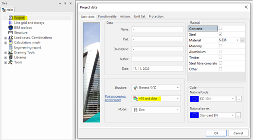
First, on the « Project » settings, let’s choose the « v16 and older » post-processing environment:
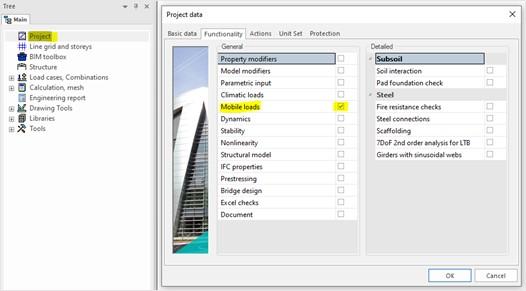
We also need to activate the "Mobile loads" functionality:
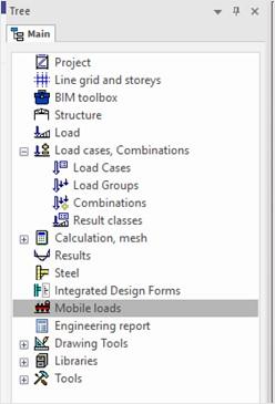
A « Mobile loads » table appears on the main tree:
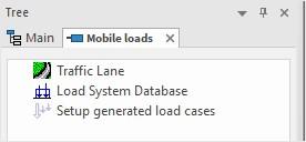
Let’s begin to create the « Traffic lane ».
The traffic lane has to be done in one time from the beginning of the beam to its end. The beam has also to be created in one element. Then, the beam can be subdivided in two parts by the third frame, and hinges can be added at each extremity.
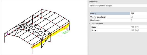
As soon as the traffic lane is created, on the menu « Mobile loads », another table appears under the « Traffic lane » : « Unit loads ».
In that menu, we don’t define the loads intensity, but only their amplification coefficient (or decrease coefficient).
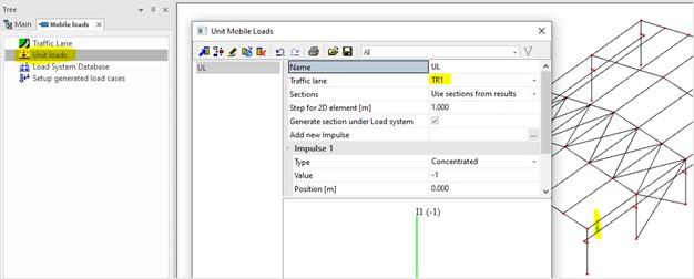
Let’s create a first case where the load would be on the middle of the frame.
The load would be divided on columns (50% of the left column and 50% on the right column).
Two vertical loads are so created with a coefficient of -0,5 in Z direction and with the adequate position:
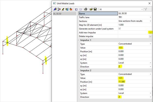
In the same way, we can create two horizontal loads in the frame plan, equal to 10% of the vertical load. So we will define a coefficient of 0,1 in the horizontal axis of the frame plan.
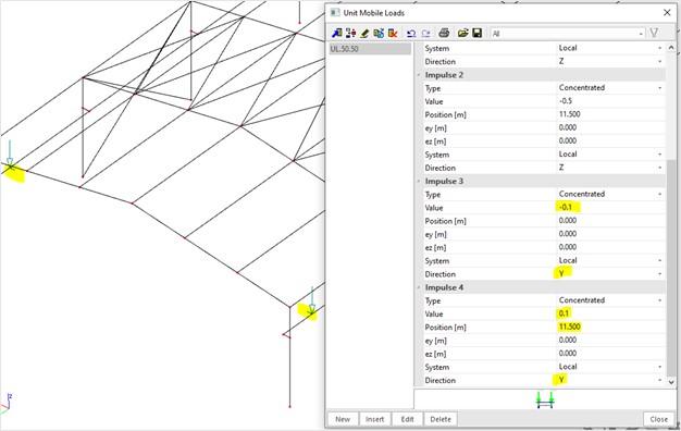
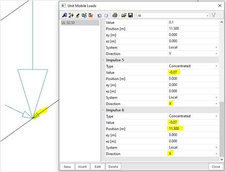
Lastly, we can create two horizontal loads out of the frame plan, equal to 7% of the vertical load. So we will define a coefficient of 0,07 in the horizontal axis out of the frame plan.
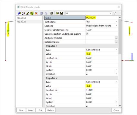
Let’s create a second case where the load would be close to the left side of the frame.
The load could be equal to 0,8 times the maximal load on the left, and 0,2 times the maximal load on the right.
To simplify, we can copy the first case and just modify the name and the coefficients:
Horizontal loads on the frame plan are still equal to 10% of the vertical loads.
Braking loads out of the frame plan are still equal to 7% of the vertical loads.
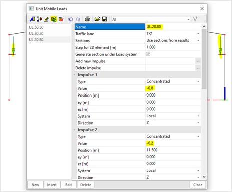
Let’s create a third case where the load would be close to the right side of the frame.
The load could be equal to 0,2 times the maximal load on the left, and 0,8 times the maximal load on the right.
To simplify, we can copy the second case and just modify the name and the coefficients:
Horizontal loads on the frame plan are still equal to 10% of the vertical loads.
Braking loads out of the frame plan are still equal to 7% of the vertical loads.
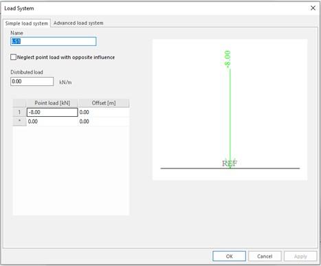
Then, we will define the loads values.
For that, still on the menu “Mobiles loads”, we can click on the table “Load system database”.
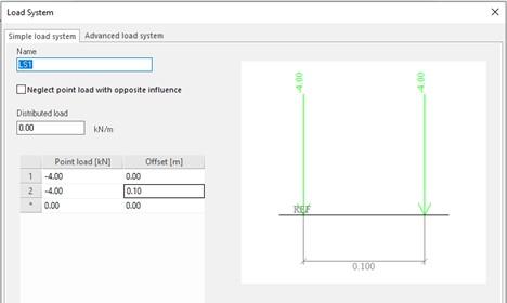
And let’s define the loads intensity :
In the case of twin loads, we could also define:
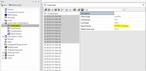
Finally, on the menu « Mobile loads », we can click on the table « Setup generated load cases » :
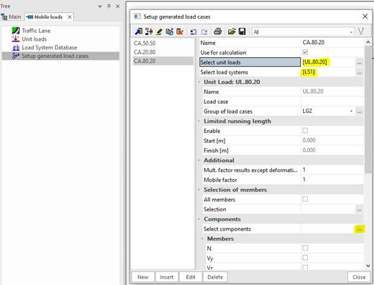
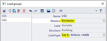
LG2 is the loads case where the envelopes will be saved. There will be an different envelope for each chosen component.
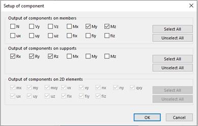
On the « Select components » table, we can choose which results we would like to see:
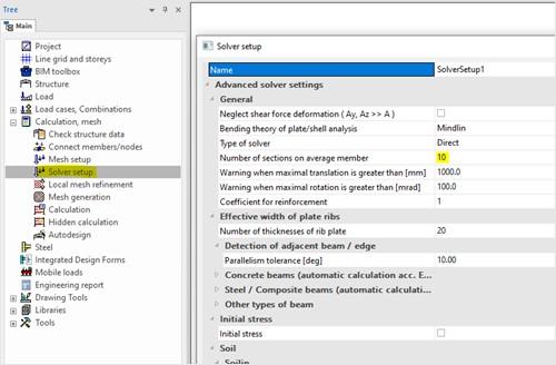
The progression step has to be configured in the “Solver setup”:
We can now run the analysis.
After analysis, on the menu « Mobile loads », we can see internal efforts on a bar, for example here My in a specific position:
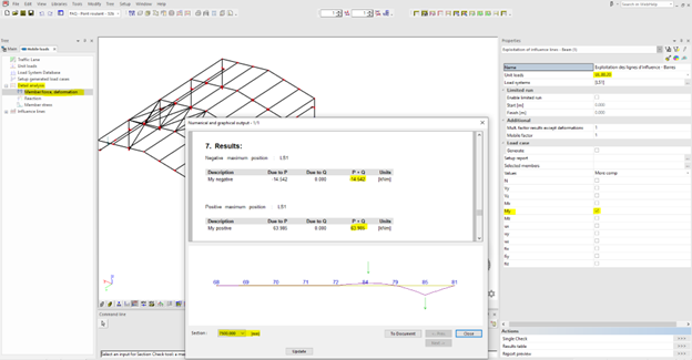
We can have a look on all load cases envelopes:
And on the menu « Results », we can ask to display maxi My moments under the load case UL.80.20 for example: we get 6,65T.m :
64 BITS VERSION
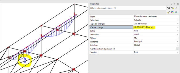
We need to define several live load cases. For example, when the maximal load is on the left of the frame (the case UL.80.20 on the 32 bits version example), we have :
These loads cases belong to loads groups with an exclusive relation (so as loads cases not be combined) :
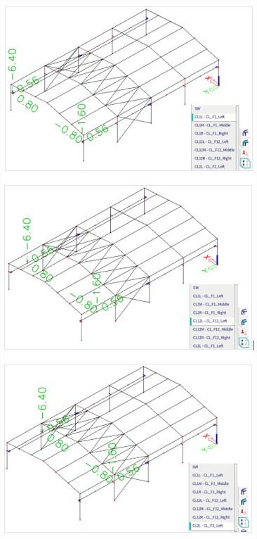
After analysis, under the case where the load is located between on the middle and on the left of the last span, we have 6,52T.m :
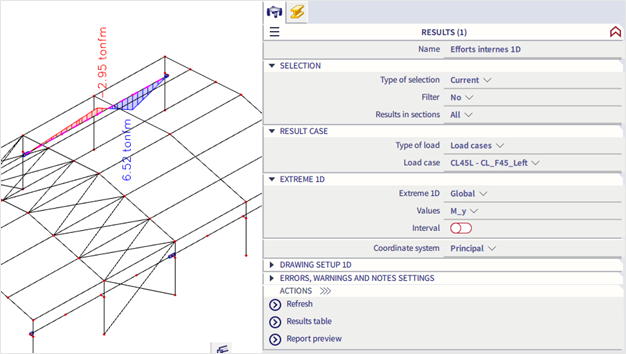
The value is very close to the one automatically displayed on the 32 bits version (which was for recall of 6,65T.m).