Define soil and water loads by using a borehole profile
Within SCIA it is possible to define soil and water loads by using a borehole profile in which you specify the different layers of the geological profile. This procedure will avoid the use of free surface loads. All the steps you need to apply are explained by the example of the following fictive soil composition:
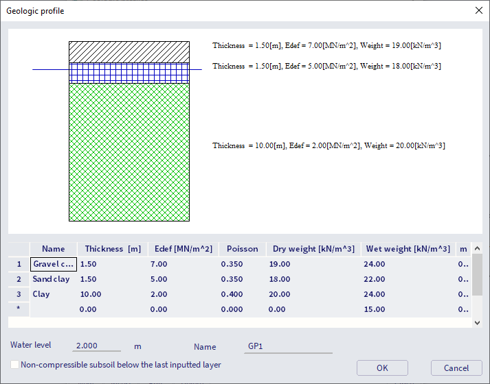
- 0 – 1,5 m: gravel clay
- 1,5 – 3 m: sand clay
- 3 – 10 m: clay
- Water level at -2 m
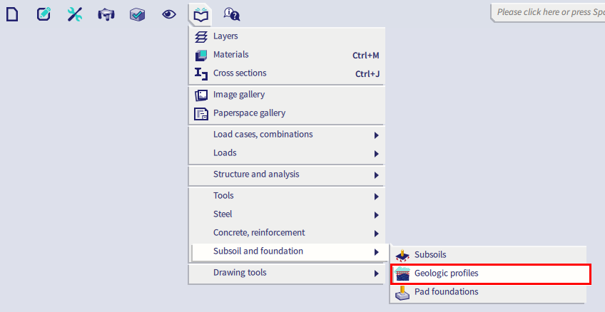
The first step of this procedure consists of creating the geological profile. The option Geological profiles can be found via Main menu > Libraries > Subsoil and foundation:
In order to create this profile, you need to define several properties which are mentioned below:
- The thickness of the layer
- The module of deformation Edef
- Poisson’s ratio
- Dry and wet weight of the soil
- The structural strength coefficient which can remain 0,20 m
- Water level
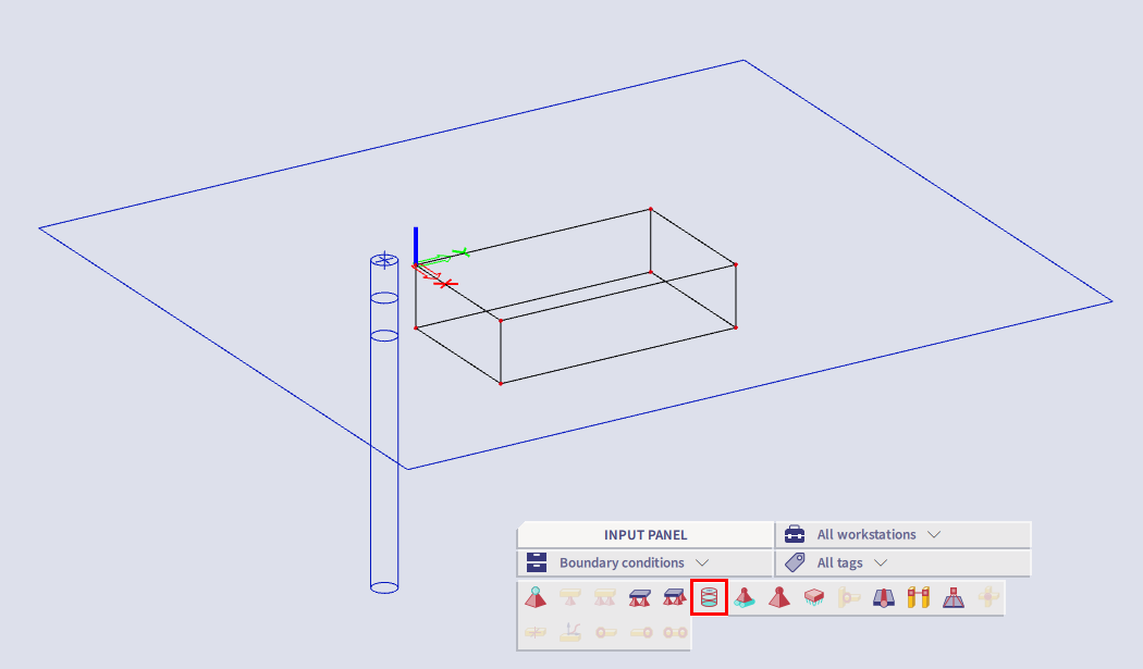
As soon as the geological profile is created, it is necessary to insert it within the model environment via a Borehole profile. A borehole profile can be inserted via Input panel > workstation Structure > category Boundary conditions. .
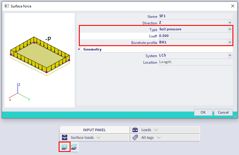
The following step consists of creating different load cases for the soil and water pressures followed by defining the loads itself. These loads can be defined by selecting the option Surface load on 2D (Input panel > workstation Loads > category Surface loads) and the Type of surface load should be set to Soil pressure. The Coefficient, which specifies the ratio between vertical and horizontal soil pressure, needs to be defined for horizontal soil pressure as well. Assume the coefficient equal to 0,5 within this example. Select the borehole profile from which you want to generate the acting loads. As soon as you confirm the properties, it is necessary to select the 2D members on which the loads should be applied and confirm with escape.
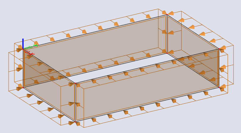
The generated soil loads will be displayed as a uniform load, please note that this is the correct behaviour:
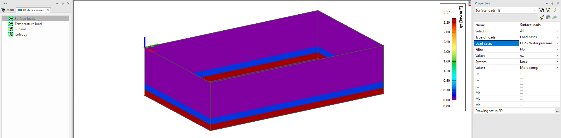
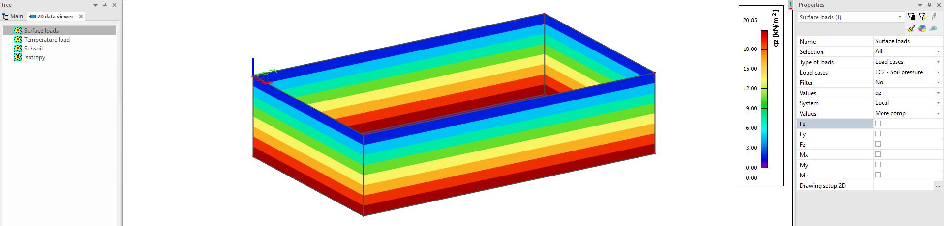
In order to check the acting loads, you can go to 2D data viewer after executing the calculation. You can review the loads for each load case in the tab Surface loads. In this case the settings qz will be selected for this load case according to the LCS of the selected member. Note that the 2D data viewer functionality is currently only available in the 32-bit version and 'v16 and older' post-processing environment of the software!
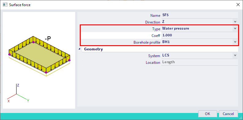
Remark: if you want to insert a water pressure, you need to select Water pressure as type of surface force. The coefficient can remain equal to 1 since there is no difference in vertical and horizontal pressure for water.