Structural model
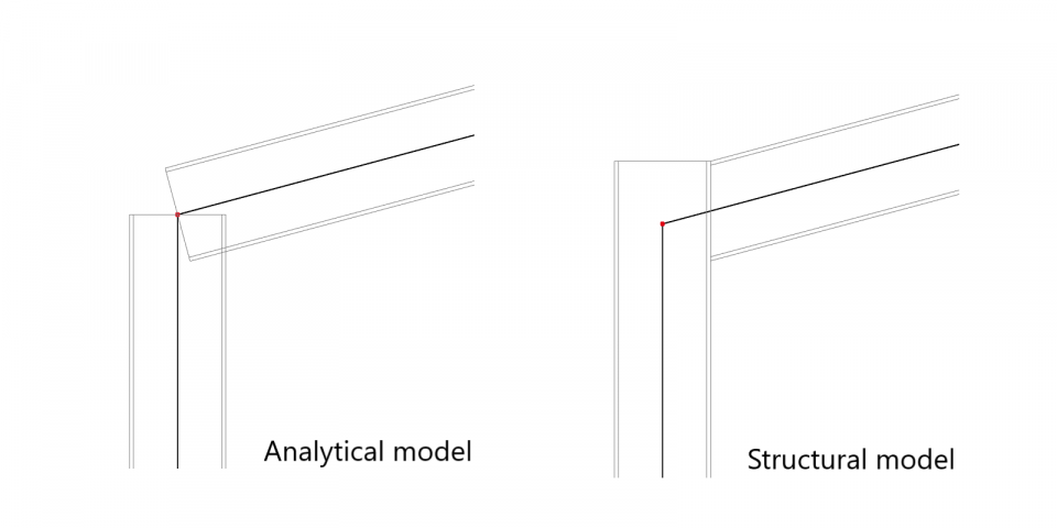
There are several different representations of a model to be considered in each project. The two representations we are dealing with in SCIA Engineer are the analytic model and the structural model.
In short:
The analytical model is used for calculations.
The structural model shows the volumes and shows how the structure will be built.
The structural model has three main functions in SCIA Engineer:
- Needed for the modelling of connections
- IFC files will export the structural model and not the analytical model
- Proper display for realistic 3D images
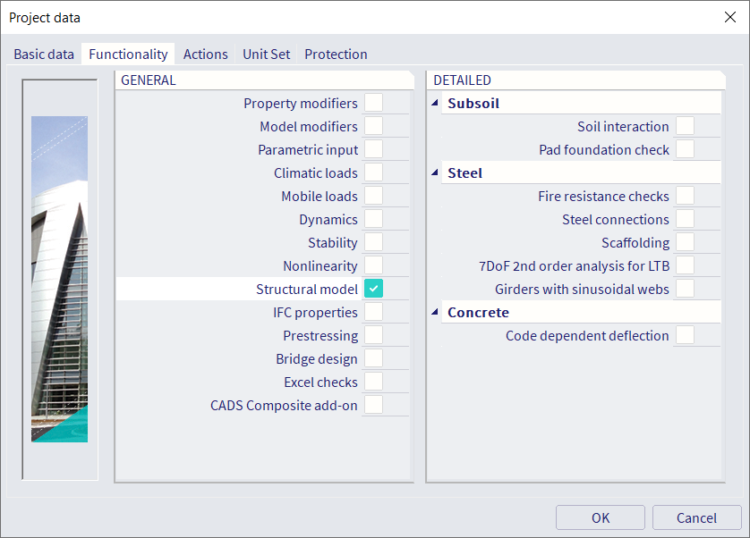
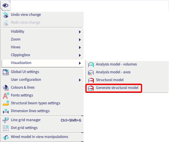
To display the structural model, the functionality needs to be activated in the project data. It will also be automatically activated when steel connections are selected. Next go to View > Set view parameters > Generate structural model.
Structural model
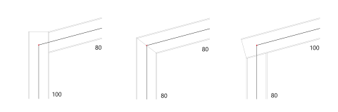
The model we build inside SCIA Engineer and use for calculation is called an analytical model. This is a simplified representation of the reality, where beams are approximated by 1D lines. Local details, like for example how the beams get cut off at the height of the column, get neglected in this calculation model. For some purposes however, for example the modelling of steel connections, it is necessary to know these details. This is why a second type of model exists inside SCIA Engineer: the structural model. In this model, beams are 3D elements and their connections are displayed as they would be in reality:
To display the structural model, the functionality needs to be activated in the project data. It will also be automatically activated when steel connections are selected.
The structural model can then be activated via the visualisation options.
Once the structural model is generated, you can switch between both models via the same menu or with the view parameters setting in the context menu (right click > view settings for all entities)

When the structural model functionality is activated, the properties window will show a section for the structural model (in advanced mode, so be sure to have all properties unfolded by showing the red arrow on the top right). Priorities, alignments, eccentricities and gaps or cuts can be defined here.The principles are explained below.
All settings are explained in detail on help.scia.net > Modelling > Geometry > Structural model.

Mode
Three mode options are available, with varying degrees of settings that will be automatically handled by the software or must be defined manually.
-
General: Only one checkbox can be changed to lock the geometry.
This mode is most suitable for members with special geometry (like solids with openings in them for instance).
Imported members often have this mode by default, but this can cause unwanted behaviour when the members are exported again to IFC. - Automatic: Settings are taken ‘automatically’ from the member definition. Default values are shown but can be changed manually.
- Manual: This mode follows the same logic as ‘Automatic’, but more options are now available for end-cuts.
Priority
The decision of which member should be continued and which member should be cut is made based on the priority of the elements. The element with the lowest priority gets cut. If elements have the same priority they both get cut at the point where they cross.
By default the priority of an element is the value displayed between brackets after the element type. This can be changed by choosing another type or overwriting the priority in the structural model section.
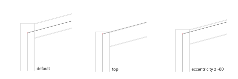
Alignment and eccentricities
With the alignment, you can change the way the member is drawn with respect to the member system line of the analytical model. They are drawn the same way by default. The line is usually in the centre of the cross-section. You can change this so for example the member is drawn under this line, with the value ‘Top’ for the alignment as shown in the picture below. Or you can define the eccentricity values manually, for instance to -80mm as shown below. Note that these changes only affect the structural model, so the eccentricities will not generate additional internal forces in the structure when calculating. This can be used when some members are for instance lower than other members, without changing the analysis model.
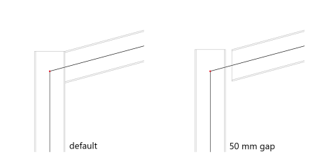
Gaps/Cuts
With end-cuts, you can define the end detail of the profile manually. A regeneration of the structural model is necessary before the changes are visible. In the example below, the structure is shown without gap first, and secondly, a gap of 50 mm is defined between the end of the beam and the column.