Buckling coefficients
This FAQ explains how to deal with buckling coefficients.
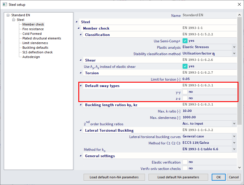
With the default setting the buckling coefficients ky and kz are automatically computed by SCIA. Therefore two approximated formulas respectively for sway and non-sway structures are used.
For a non-sway structure the formula is:
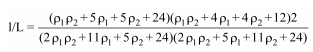
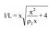
For a sway structure the formula is:
With:
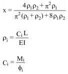
- L = system length
- E = elasticity modulus (Young)
- I = moment of inertia
- Ci = stiffness in node i
- Mi = moment in node i
- φi = rotation in node i
The values for Mi and φi are approximately determined by the internal forces and the deformations, calculated by load cases which generate deformation forms, having an affinity with the buckling shape.
The following load cases are considered:
- load case 1: on the beams, the local distributed loads qy=1 N/m and qz=-100 N/m are used, on the columns the global distributed loads Qx =10000 N/m and Qy =10000 N/m are used
- load case 2: on the beams, the local distributed loads qy=-1 N/m and qz=-100 N/m are used, on the columns the global distributed loads Qx =-10000 N/m and Qy=-10000 N/m are used
These formulas produce buckling coefficients with a value larger than 1 (sway) or smaller than 1 (non-sway).
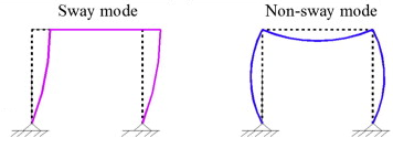
The concept of a sway or non-sway structure is directly linked to the critical load coefficient αcr from a stability analysis (see as reference ECCS 119):
- When αcr ≥ 10, the structure is non-sway, therefore the buckling coefficients will be smaller than 1.
- When αcr < 10, the structure is sway, therefore the buckling coefficients will be larger than 1.
Hence, you should perform a stability analysis prior to setup the sway / non-sway parameter to optimize at the best the computed buckling coefficients ky and kz to be used in linear analysis.
- If αcr ≥ 10, then you can simply perform a linear analysis specifying, in the steel settings, the non-sway behavior of the structure for the y-y and z-z directions, so that the non-sway formula will be used to compute the buckling coefficients of all members.
- In case αcr <10, you can choose to perform a linear analysis using sway buckling factors (which are always larger than 1). This method results in a much simpler analysis with respect to a second-order analysis accounting for global and local imperfections. However, you should carefully check that this possibility is allowed in the used design norm (for instance, the Belgian national annex of Eurocode currently does not allow this method, thus requiring a second order analysis). Also, note that this method is more conservative with respect to a second-order calculation accounting for global and local imperfections.
Also important, the formulas used for the computation of ky and kz are valid only in case of frame structures with perpendicular rigid and/or semi-rigid connections. This limitation implies that the ky and kz values automatically computed by SCIA should be critically checked when the application case is different from the one specified above.
In such cases you have several options:
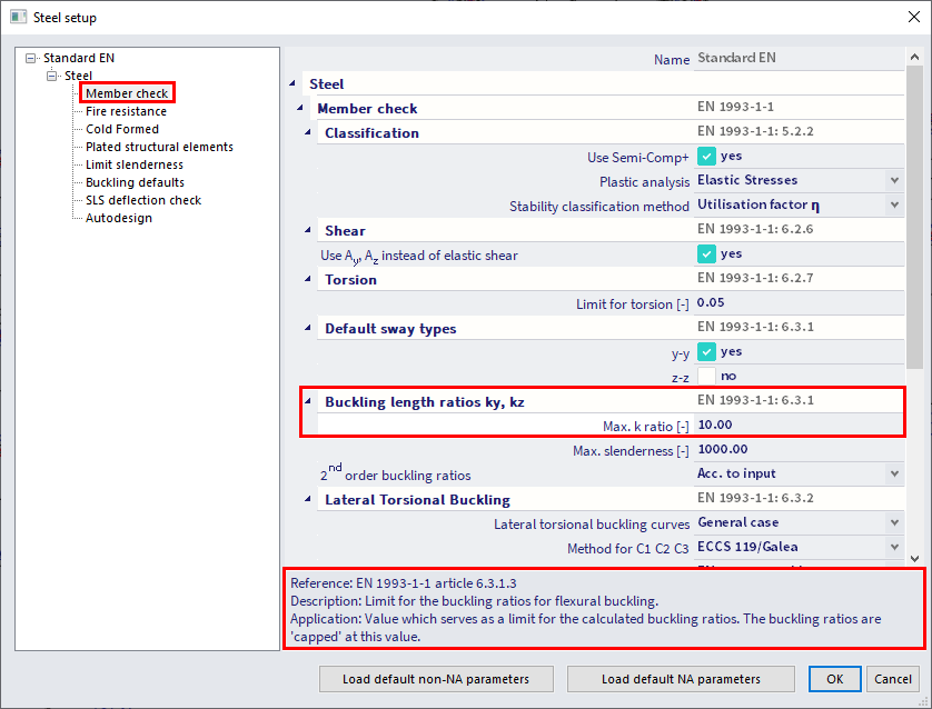
- Limitation of the computed ky and kz, to be set in the steel settings:
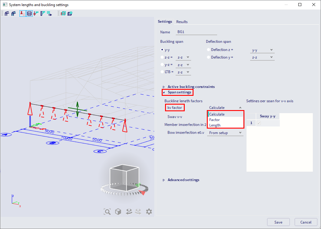
- Manual input of the buckling coefficient or buckling length, to be set in the system lengths and buckling settings dialog:
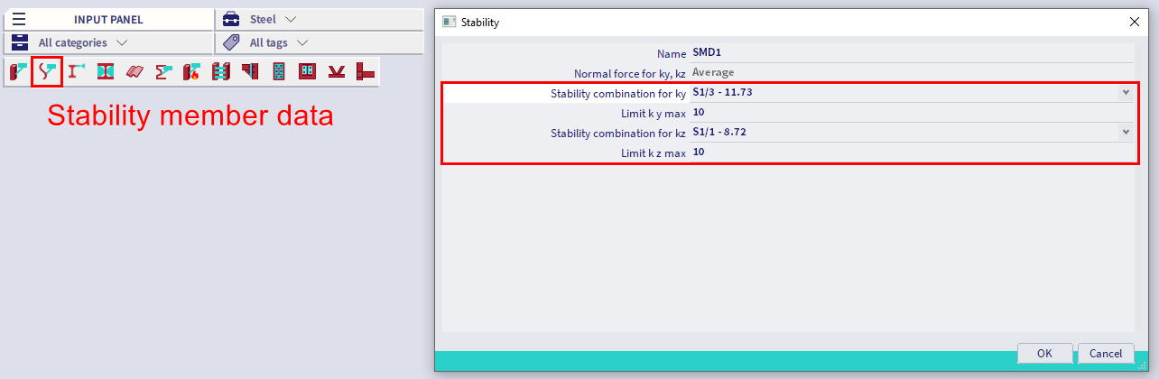
- Numerical computation of the buckling coefficient via stability analysis. In this last case a stability analysis should be performed and the instability mode of the element for which the ky and kz are looked for should be retrieved. Once this has been done, these stability modes can be applied to the element via Input panel > workstation Steel > Stability member data: