Defining a section on a 2D member
A section can be applied when you only want to display results over a particular part of the structure. The only function of a section lies in the graphical representation of results and can be applied both for 2D and 1D members. The sections for 2D elements show the results on a line by means of a section while the sections for 1D elements show the results in a point.
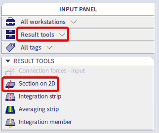
A section on a 2D member can be accessed within Input panel > Result tools > section on 2D.
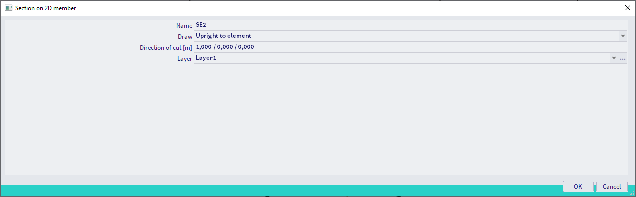
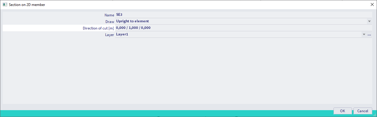
When applying sections on 2D members, it is very important to define its properties correctly. The property ‘Draw’ defines the plane in which the results of the section are shown. The property ‘Direction of cut [m]’ represents the section plane which is defined by a line and by an in-plane vector. This means the section plane will be created perpendicular on the element within the defined direction, more specifically in Z plane for the picture below.
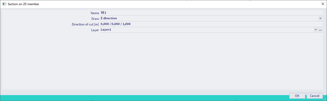
Subsequently, a section can be drawn as a straight line of which you input the begin and end point.
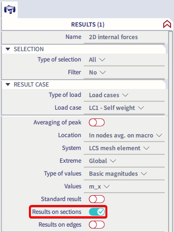
When generating the results, you can choose between the output settings ‘Standard result’ and ‘Results on sections’ within the properties. The standard results will provide a result for the entire element and the results on sections will only display the results on one or multiple sections. However, it is possible to display both values simultaneously.
The interpretation of the results on sections can be defined by the user as well within the result properties, more specifically the ‘Course’. The course ‘Precise’ will provide a precise representation of the results based on the mesh. The ‘Trapezoidal’ course will generate a trapezoidal distribution of the results on the section while the course ‘Average’ will display an average result along the length of the section.
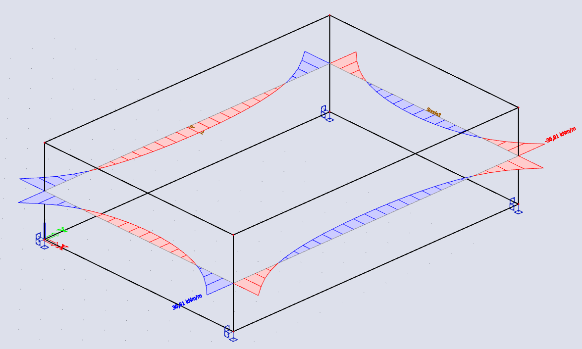
The effects of the section’s properties – draw and direction of cut – are shown by the following example.
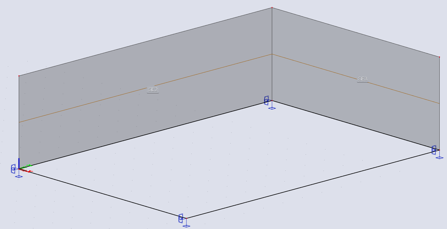
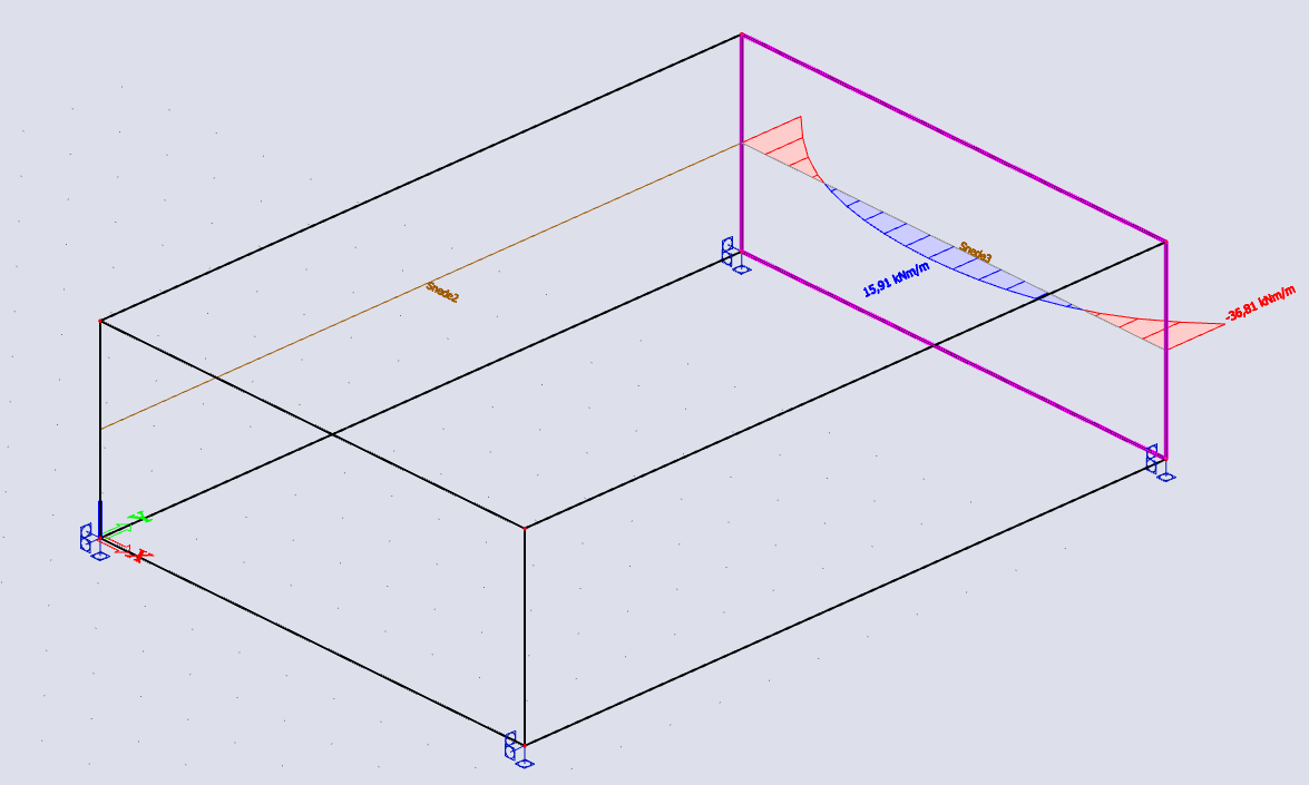
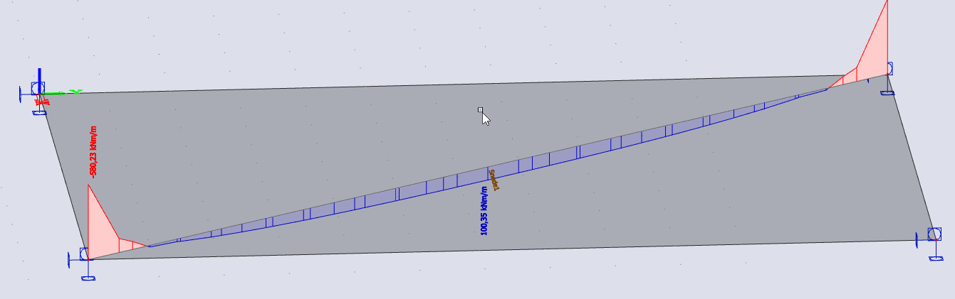
Both sections have different properties, but will represent the same result. Section 1 is drawn in direction Y and has a cutting direction X (1,0,0). Section 2 is drawn in direction X and has a cutting direction Y (0,1,0). For both sections, it is best to set the draw on upright to element. If chosen for direction Y, no results will be shown on the sections, which are parallel to this direction Y. The result for section 1 is the same as the result for section 2 and looks as follows:
Tip and trick:
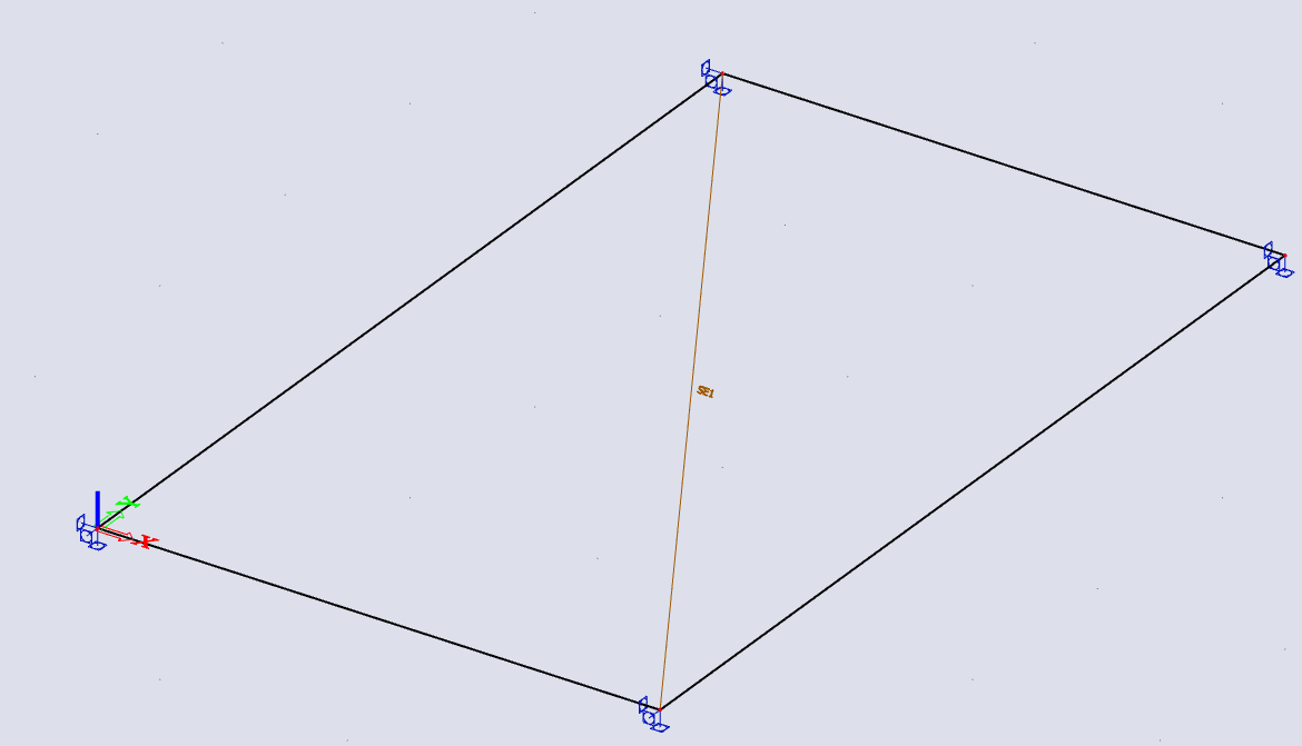
It is possible to display the results on sections for only one element instead of all elements. In order to generate this output, you have to select the section and 2D element for which you want to generate results and set the type of selection to ‘Current’ within the result properties. The following picture provides a graphical representation of the results of section SE1 for the 2D element E5.