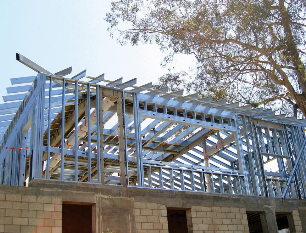
Highlights
- Design of cold-formed steel members according to AISI S100 fully integrated in the standard SCIA Engineer steel design environment.
- Derivation of effective shape, including distortional buckling for internal and edge stiffeners and double edge folds.
- Effective section of library and general cross-sections: support for any arbitrary shape, also when imported from CAD software.
- Advanced checks of web crippling, also for sections with stiffened webs.
- Special purlin design checks including derivation of free flange geometry, checks under gravity and uplift loading.
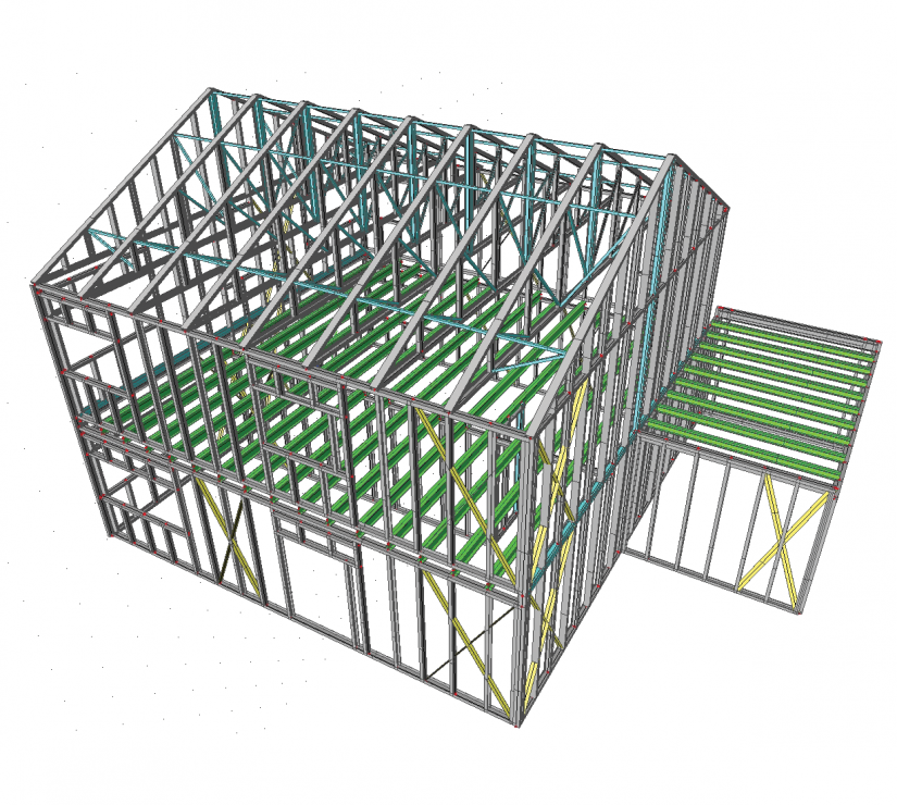
The steel design module Cold-Formed Steel design for the IBC is an extension to the module sensd.01.ibc Steel design. It enables the design of cold-formed steel members according to the North American specification AISI NAS S100: 2016.
- Both section and stability checks are supported: you execute these in the same way as for conventional steel members;
- Built-in decision mechanisms determine which code articles are to be used, based on the geometry, internal forces, presence of sheeting and other model parameters.
- The reduced effective section properties due to local and distortional buckling are taken into account in all checks;
- The specialised design procedures for failure under web crippling and for purlins attached to sheeting are applied as specified in the code.
Benefits
- sensd.02 analyses a wide variety of open steel sections for local buckling effects;
- Effective cross-sections are derived for compression, strong- and weak-axis bending; these are then used in the general steel code checks, where necessary, and can be displayed graphically.
- The effective shape derivation takes into account distortional buckling of edge and intermediate stiffeners and double edge folds;
- The intelligence behind the effective section calculation increases productivity by requiring very limited user input;
- The Profile Library contains a wide variety of products from cold-formed steel manufacturers; the dimensions of these profiles can also be edited by the user, thus extending the Profile Library with more products;
- Using General Cross-section Editor (included in module sen.05), users can define custom cross-sections; including import from dxf and dwg files;
- The supporting effect of steel sheeting is taken into account for economical purlin design. A library of sheeting products from popular manufacturers is also available.
- An automated optimisation procedure (AutoDesign) in the steel design functionality selects suitable profiles depending on (1) the internal forces in the structure and slenderness of members and (2) the set of preferred profiles selected by the user.
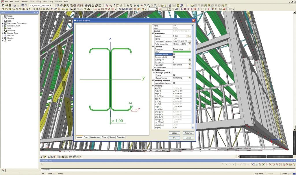
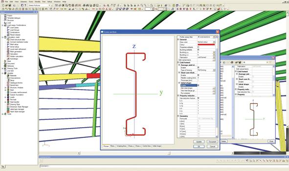
Initial Shape
A cold formed section can be selected from the Profile Library or modelled as a general cross-section. Then, the so-called initial shape is automatically calculated: the cross-section is divided to its parts, i.e. walls and stiffeners. Automatically recognised part types are:
- I (internal)
- F (fixed – no reduction is needed)
- SO (symmetrical outstand)
- UO (asymmetrical outstand)
- RUO (reinforced unsymmetrical outstand)
The generated initial shape can be viewed and modified. A tool is available directly in the Profile Library to let you to check the effective shape calculation without having to run the steel design.
Effective shape
Calculation of the effective widths always starts with the determination of the stress in the compression element. The obtained effective sections can be displayed graphically.
Supported cross-section types
The following cross-section types are supported for generation of the initial shape and effective cross-section:
- Standard cross-sections from the Profile Library;
- Thin-walled geometric sections (defined by their shape and thickness);
- Paired cold-formed steel profiles (e.g. a back-to-back Sigma section);
- General thin-walled sections or general polygons with thin-walled representation;
Section Checks
The following section checks are executed: axial tension, axial compression, bending moment, shear force, torsional moment, web crippling, combined tension and bending, combined compression and bending, combined shear, axial force and bending moment, combined bending and web crippling.
Stability Checks
The following stability checks are executed: flexural buckling, torsional and torsional-flexural buckling, lateral-torsional buckling, bending and axial compression, bending and axial tension, combined bending and tension check. For determining the torsional-flexural buckling resistance, the general cubic equation is applied.
Additional steel member features
To improve stability, additional elements may be included in the model - sheeting diaphragms, lateral-torsional buckling restraints, web stiffeners.
Also the second order analysis according to Appendix 2 is supported.
Diaphragms and one flange sheeting fastening
The available lateral strength of steel sheeting is checked; this allows for the torsional stiffness of a member to be augmented. SCIA Engineer also allows for a flange of flexural and compression members to be considered as fastened to sheeting, as specified in AISI NAS 2007, when the conditions for applicability are satisfied.
Web crippling data
Web crippling (local failure of the web due to high local intensity of the load) is checked at locations of point loads, or at locations of connection between members: e.g. a purlin connected to a rafter. The web crippling check is executed only for shear force Vy in the positions where there is a jump in the shear force diagram, but it can be disabled.
Lapped purlin design
C-profiles and Z-profiles can be ‘lapped’ (shoved into one another) to create one semi-continuous purlin from separate purlins. You can introduce lap zones on purlins (both symmetrical and asymmetrical). When the check is executed in a section located in the lapped zone, the combined strength of both sections is used. The overlap can optionally be fully braced at the bottom flange.
The lapped length can be optimized by the application based on a defined dimension list.
Required modules:
- sensd.01.ibc

Want to try SCIA Engineer yourself?
Explore how our software and services can help you optimise your work and boost your productivity. Try it for yourself with a free 30-day software trial.
Download a free 30-days full trial