Highlights
- Outstanding management of large scaffolding projects with detailed modelling of all scaffolding parts.
- Addressing of large deformations, non-linear stability and various other types of nonlinearities on the level of analysis explicitly.
- Input of initial deformation based on stability analysis results, including nonlinear behaviour of members and connections.
- Semi-automatic determination of buckling lengths based on the deformation response obtained from FEM analysis.
- Specific checks for members and couplers according to EN 12810 and EN 12811, in combination with EC3 and EC9.
A number of generic and dedicated technologies in SCIA Engineer let engineers perform real Computer Aided Engineering in the field of scaffolding design: parametric blocks for faster modelling, project templates with loads and predefined reports, and advanced analysis options that cover various types of nonlinearity. SCIA Engineer combines these features with member and connection (coupler) checks for scaffolding structures according to EN 12811-1 and to manufacturer specifications.
Scaffolding types
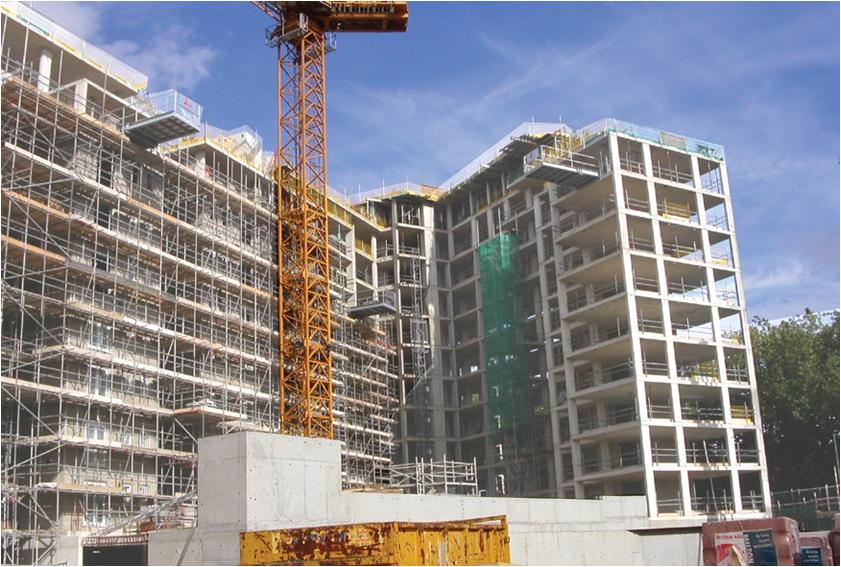
SCIA Engineer has been successfully used for years as an indispensable tool for the analysis and design of the following types of scaffold:
Tube & Coupler scaffolding
Used widely because of their versatility, their adaptable components allow to build complex geometries easily.
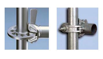
SCIA Engineer models these using coupler types defined in Annex C of EN 12811-1 and custom manufacturer couples from Cuplock and Layher.
Couplers are available as an extensive library, where generic and manufacturers products are represented as sophisticated tri-dimensional hinges, nonlinear in both their translational and rotational response.
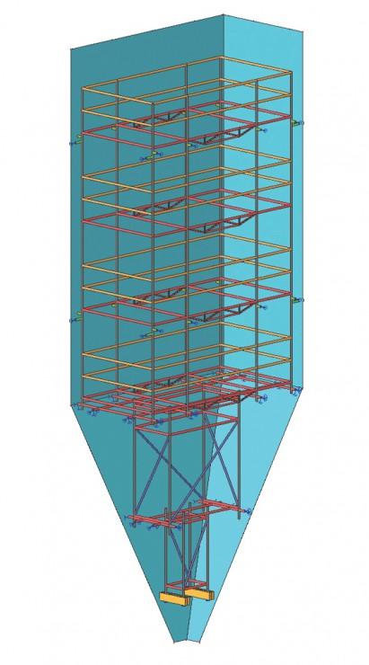
Modular systems
Defined as systems in which the standards provide components for the connection to the other scaffold components (transoms and ledgers) at predefined (modular) intervals, their main advantage is a short erection time.
SCIA Engineer eases the modelling of such scaffolds by the possibility to create libraries of User Blocks to be inserted in new projects.
Frame systems
A special type of modular system, in which standards and transoms are already welded together as fixed frames.
Again, the application of User Blocks and parametric templates allow for quick and error-free model generation.
Modelling
Steel as well as aluminium materials are available for modelling and analysis of scaffold members.
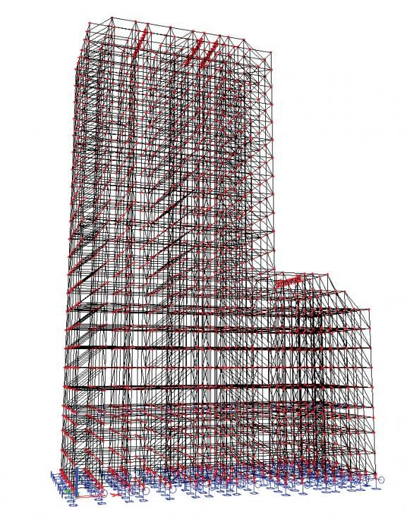
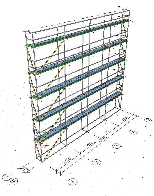
Direct Scaffold Modelling
All standard modelling and manipulation (copy, move, mirror, etc.) functions and all available tools (UCS, activity, layers, etc.) of the generic SCIA Engineer environment are used for setting up an analysis and structural (or CAD) model of the scaffold.
If a 2D or 3D CAD model of the scaffold is available, this can be directly imported to serve as an analysis model. Even architectural models can be imported, which allows you to model the scaffold next to the existing building.
In addition, any pre-prepared User Blocks, i.e. standardised or parametric blocks of geometry defined by you in advance (e.g. templates for commonly used frame systems) can be inserted into the model of the analysed scaffold.
Scaffolding Templates
Engineers who deal with the design of scaffolds regularly will benefit from the possibility to prepare tailor-made templates for all types of scaffolds they have to handle. The advantage of using templates is that all common data (e.g. materials, cross-sections, stiffnesses, combinations, basic geometry, etc.) are defined just once – on creation of the template.
Templates save a lot of effort also because they may contain all required load cases and combinations.
Analysis
The analysis of the scaffold includes proper definition of loads and combinations, calculation, and design in compliance with the scaffolding-related codes.
Calculation
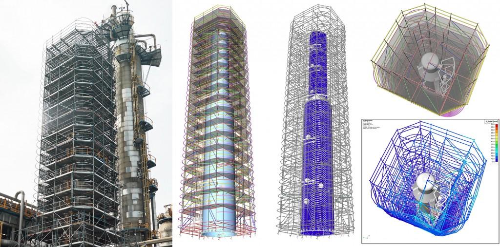
Advanced second order analysis which includes both global (P-Δ) and local (P-δ) effects is often required for scaffolding structures (contained in module sens.00). Other calculation features from this module are used for the handling of the various specifics of scaffold structures: non-linear functions for coupler stiffness, friction supports for base jacks, pressure-only supports for abutments, gap elements for margins between the pen and hole, etc.
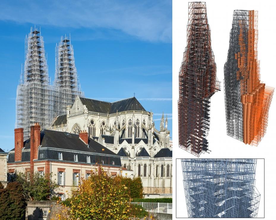
SCIA Engineer also supports stability analysis, which is used to determine the buckling shapes of the scaffold (module sens.01). The buckling shapes are then used as imperfections for the full second order analysis. Nonlinear stability analysis (contained in module sens.03) lets you e.g., eliminate tension-only elements or take into account other member and support nonlinearities for the determination of buckling response of the scaffold.
Design: limit states
In the ultimate limit state, the scaffold members are checked using the capacity and interaction checks defined in EN 12811-1. In addition to the specific scaffolding checks, full design and check of the structure according to EN 1993-1-1 is also available for those scaffolds which do not meet the EN 12811 prerequisites.
SCIA Engineer also performs a coupler check as defined in EN 12811-1 or in manufacturer specifications (for specialised coupler products).
Moreover, you can evaluate the deformations of the scaffold and easily check deflections. This is particularly important for ledgers that support floorboards.
More on Code checks
In typical scaffolding projects, columns are considered continuous although they contain flexible hinges along their lengths. For the correct design of these scaffolding elements, system lengths and buckling lengths need to be correctly taken into account. If the scaffolding functionality is used, this is handled correctly: flexible connections between members do not interfere with system lengths and these are also taken into account in the FEM-based determination of buckling lengths.
For the scaffolding members (standers, transoms), the Eurocode Steel and Aluminium code check are extended with checks according to the Scaffolding code EN 12811-1. Additions have been made for tube members: interaction equations according to art. 10.3.3.2 and to DIN 4420 part 1 in the case of high shear.
For the connections:
- you assign non-linear coupler hinges to nodes connecting standards with horizontal elements, standards with diagonals, and beams with beams. The nonlinear hinges are selected from a predefined library list.
- for generic couplers, resistance values are compared against the design forces (Annex C of EN12811-1) and the combination of actions is checked (art. 10.3.3.5, equation 10 and 11). The library provides the following generic type of couplers:
- right-angle coupler
- sleeve coupler
- swivel coupler
- parallel coupler
- manufacturer products from Layher and Cuplock are checked according to the rules in the specification documents;
- base jacks are checked according to Eurocode (the ultimate moment Mu depends on the axial force in the selected standard);
Drawings
A separate module [see sendt.01 - Automated General Arrangement Drawings] is a very effective tool for the automatic generation of 2D and 3D overview drawings of the structure. The generated images can be edited, combined with other drawings and inserted into the PaperSpace gallery to make professional plots. All drawings are still linked to the original model, which means that they are automatically regenerated after modifications of the model.
Tailored workflows
Scaffolding components
SCIA Engineer allows for an accurate modelling of different scaffolding components including their appropriate specifics.
Diagonals
Diagonals are typically attached with an eccentricity due to the geometry of the attachment between the standards and the diagonals. In addition to the eccentricity, a special behaviour of diagonals in modular systems is that they mostly have a small gap along their length, caused by a slight margin between the pen and hole. If specific test results for the diagonals of modular systems are available, the stiffness derived from the tests can be accounted for using a translation spring.
Custom couplers
SCIA Engineer integrates an extensive library of couplers which contains the different types given in Annex C to EN 12811-1 including their stiffness. You can also add your own couplers to this open library.
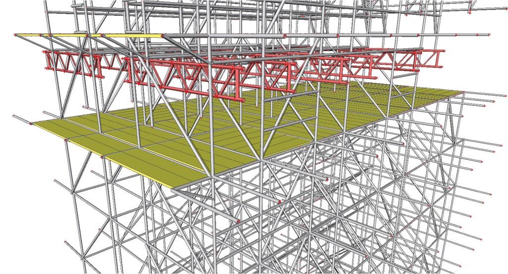
Floor elements
Scaffolding structures typically have two types of floor systems: metal boards or wooden planks.
The metal floorboards are accounted for in the stiffness of the analysis model. If wooden planks are used, however, the stiffness of the planks should not be taken into account since the planks are put loose on the transoms. In this case, the planks are ideally modelled as an extra load.
Base jacks
Base jacks at the bottom of the scaffold feature specific behaviour. In most cases, the base jacks are not fixed to the ground: their horizontal resistance depends purely on friction. This is modelled using friction supports.
Façade anchors
Also the connection between the ties and the façade as specified in EN 12810-2 is effectively modelled.
Required modules:
- sen.00
- sensd.01.en

Want to try SCIA Engineer yourself?
Explore how our software and services can help you optimise your work and boost your productivity. Try it for yourself with a free 30-day software trial.
Download a free 30-days full trial