Interpolation of FEM results on 2D members
The Finite Elements Mesh in SCIA Engineer exists of linear 3- and/or 4-angular elements. Per mesh element 3 or 4 results are calculated, one in each node. When asking the results on 2D members, the option ‘Location’ in the Properties window gives the possibility to display these results in 4 ways: 'In centres', ‘In nodes no avg.’, ‘In nodes avg.’ or ‘In nodes avg. on macro’.
When we run the initial FEM calculation, the solver calculates at first the internal forces in the integration points. An integration point is a point within a finite element at which integrals are evaluated numerically. These points are chosen in such a way that the results for a particular integration scheme are the most accurate.
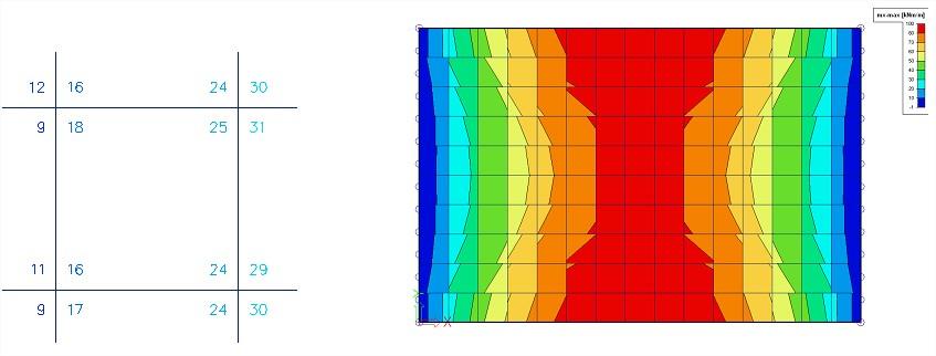
In nodes, no average
All of the values of the results are taken into account, there is no averaging (the calculated values from the integration points are extrapolated to the nodes of the finite element). In each node are therefore the 4 values of the adjacent mesh elements shown. If these 4 results differ a lot from each other, we'll see significant colour jumps between adjacent mesh elements. This is an indication that the chosen mesh size is too large.
This display of results therefore gives a good idea of the discretization error in the calculation model.
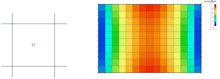
In centers
Per finite element, the mean value of the results in the nodes of that element is calculated. Since there is only 1 (averaged) result per finite element, the display of isobands becomes a mosaic. The advantage of this is that it averages the results over the area of the finite element. The course over a section is a curve with a constant step per mesh element.
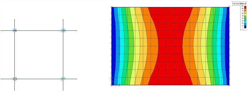
In nodes, average
For every mesh node the values of the results of adjacent finite elements are averaged as a mean value. Because of this, the graphical display is a smooth course of isobands.
This type of results can be used for a single 2D member but in certain cases, it is not permissible to average the values of the results in the common node:
- At the transition between 2D members (plates, walls, shells) with different local axes.
- If a result is really discontinuous, like the shear force at the place of a line support in a plate. The peaks will disappear completely by the averaging of positive and negative shear forces.
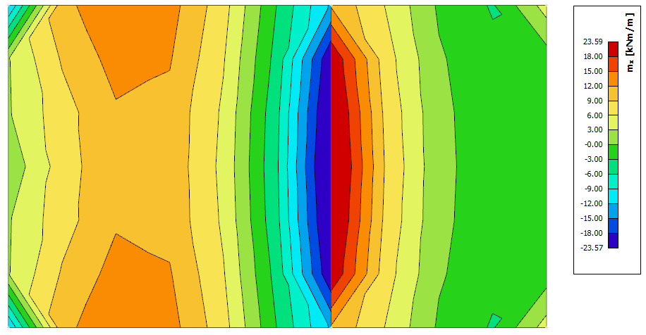
In nodes, average on macro
For every mesh node the values of the results are averaged per node only over mesh elements which belong to the same 2D member ánd which have the same directions of their local axes. This resolves the problems mentioned at the option ‘In nodes, average’.
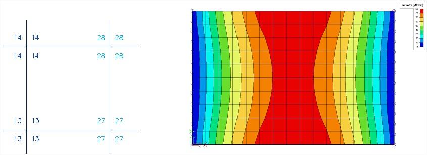
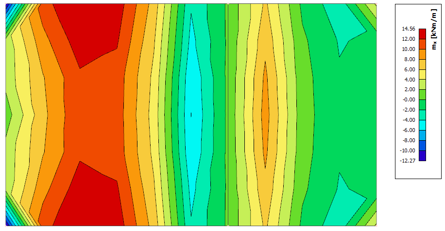
The difference between the last two options is further explained below.
'In nodes average on macro' shows us that there is a moment between the blue and red zone that results in a negative and positive peak on it's left and right side.
'In nodes average' calculates the mean value of these peaks resulting in a value near zero. This might give us an incorrect result.
Accuracy of the results
If the results according to the 4 locations differ a lot, then the results are inaccurate and the mesh has to be refined. A basic rule for a good size of the mesh elements, is to take 1 to 2 times the thickness of the plate.