Highlights
- User-defined templates for prestressing reinforcement in pre-tensioned/posttensioned concrete members
- Fast re-use of templates in other projects
- Parameterisation of the reinforcement templates
- Possibility to input bore holes patterns by means of a dwg/dxf file
- Asymmetrical strand patterns
- Direct input of internal and external posttensioned tendons
- Import of tendon geometry through DXF, DWG, XML
- Export of tendons to CAD programs for the finalisation of drawings
- Time-dependent analysis of the structure taking into account the age of concrete.
- Calculation of losses due to creep, shrinkage, and relaxation of prestressed tendons.
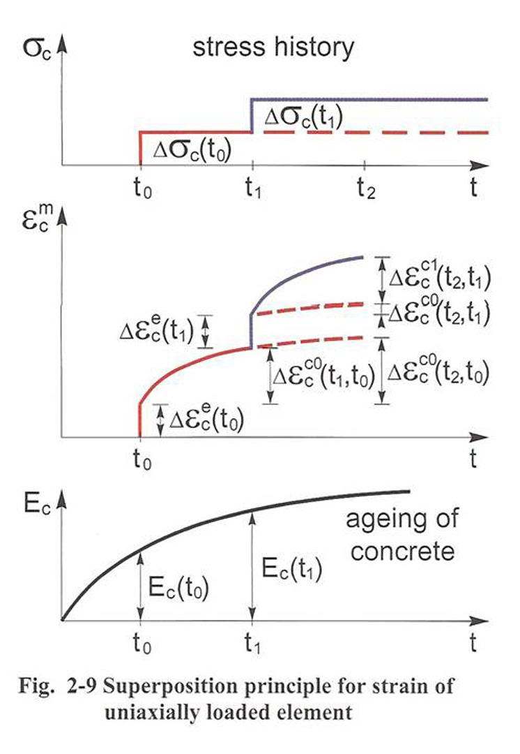
- Calculation of concrete strain using superposition.
- Load is changed only in discrete time node.
- Numerical method described in annex KK.3 in EN 1992-2.
This module enables you to introduce tendons with 3D geometry and calculate losses of prestressing. It includes automatic generation of eccentric finite elements for group of tendons (tendons become a part of the structural model) and calculation of equivalent load, internal forces and stresses caused by prestressing. We recommend to use this module in combination with the modules “Construction stages” sens.20 and “Prestressed concrete design” module sencd.06.en.
Strand-patterns
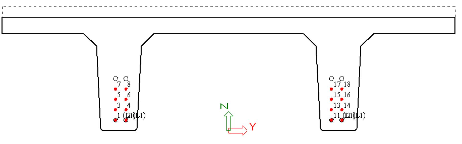
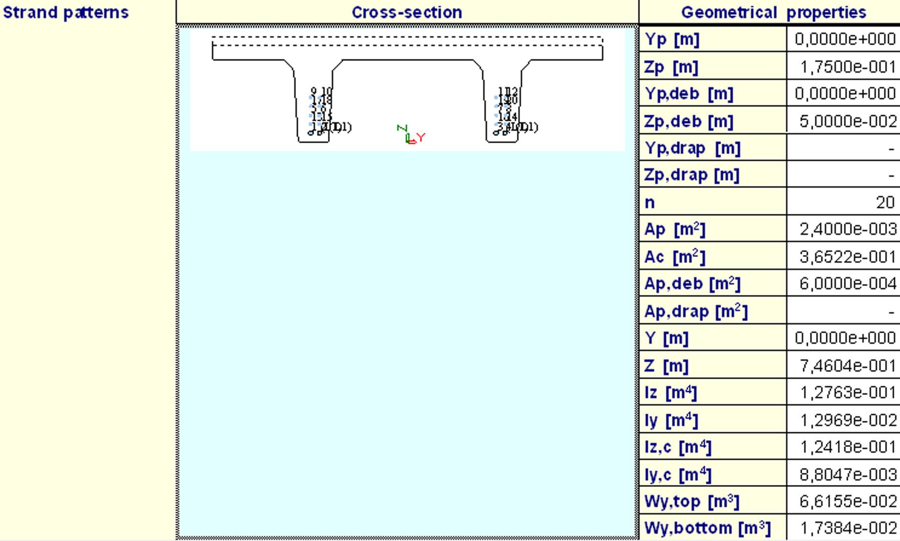
Strand-patterns enable the user to quickly and easily model pre-tensioned/post-tensioned concrete members in accordance with their daily practice. The user utilises what is termed borehole and strand patterns in order to input individual strands and adjust their properties such as the initial stress, debonding length, draping distance, type of strand, etc. The user can store the borehole- and strand-patterns in libraries and retrieve them back when needed thus, attributing to a standardised company-wide solution for strand layout in members. Consequently, the application of this module in combination with the module for parameterisation provides the user with a very effective solution for precast pre-tensioned members.
The philosophy of what is termed a “super-user” enables the customer to assign a “super user” who can create and maintain strand patterns and individual templates/parameters. An “ordinary user” is then only able to use the templates with strand patterns created by this “super user” in a quick and easy way, without the possibility to use a noncompany strand pattern or to enter incorrect input values. The library can be stored by the “super user” on the company server and it can be even made accessible to customer’s clients through the Internet. Various data for the cross-section can be imported from DWG or DXF file, attributing to a quick conversion of old calculation practice into the new SCIA Engineer integrated solution.
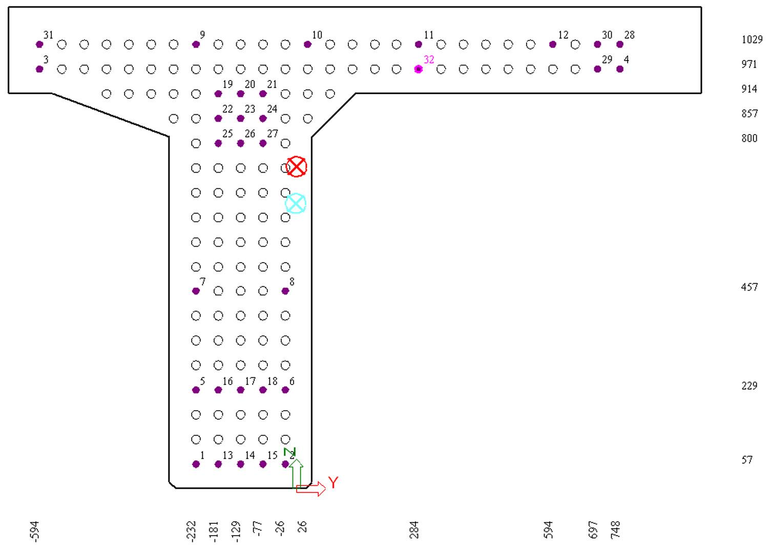
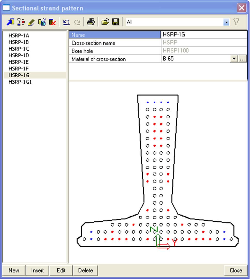
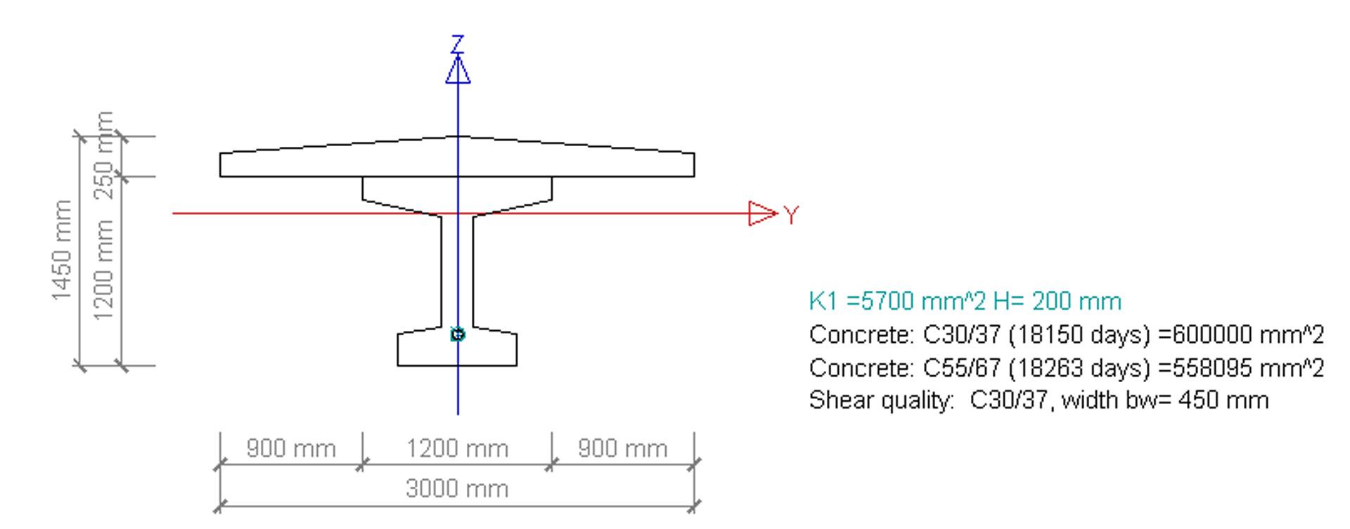
The input dialogue for strand patterns is straightforward and corresponds to the needs of design practice. The user can see in one glance the centre of gravity for both the prestressing and cross-section. For asymmetrical cross-sections like T-shapes used at ends of bridges this contributes to a proper design of prestressing. The table of geometrical data calculates on-line the data related to the prestressing and cracked concrete section while the user is still inputting the strand layout. These data include, for example, the moment of inertia, area of concrete without the strands, section modulus at top fibres, etc. The user can easily assign debonded and draped strands. Even curved members can be prestressed using the draping functions. All prestressing materials can be used, like wires, strands and bars. This means that structures like asymmetrical T’s, hollow core slabs, double T’s, foundation piles, lattice girder slabs, and others can be modelled.
All entered data can be reviewed in the graphical window of SCIA Engineer and, if necessary, easily adapted. View parameters help the user to change the picture of the strand pattern according to the company practice; the same picture will be stored in the document. Other data available for printing include, for instance, the initial stresses, borehole patterns and strand properties.
Tendons
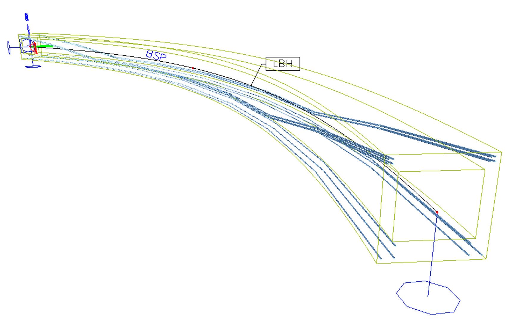
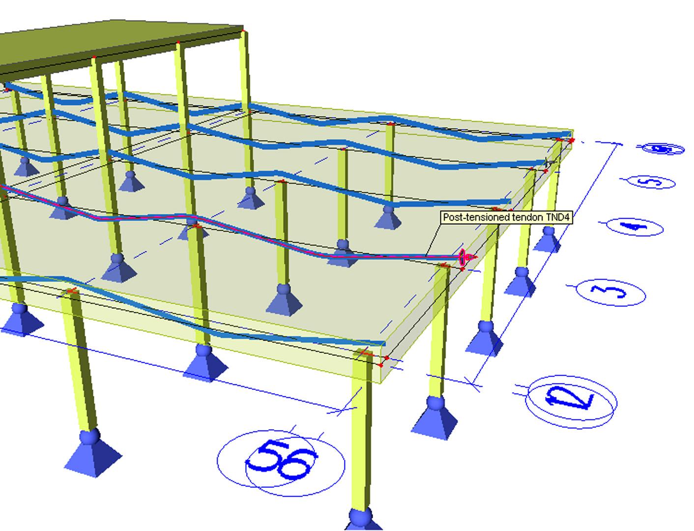
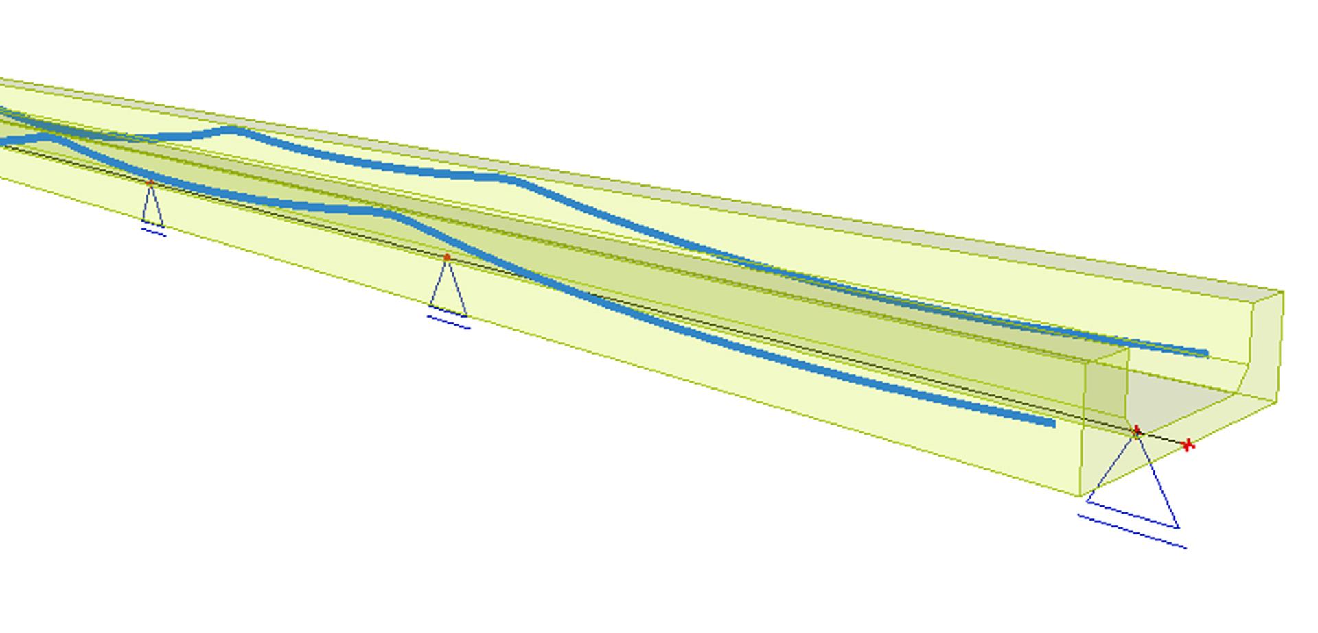
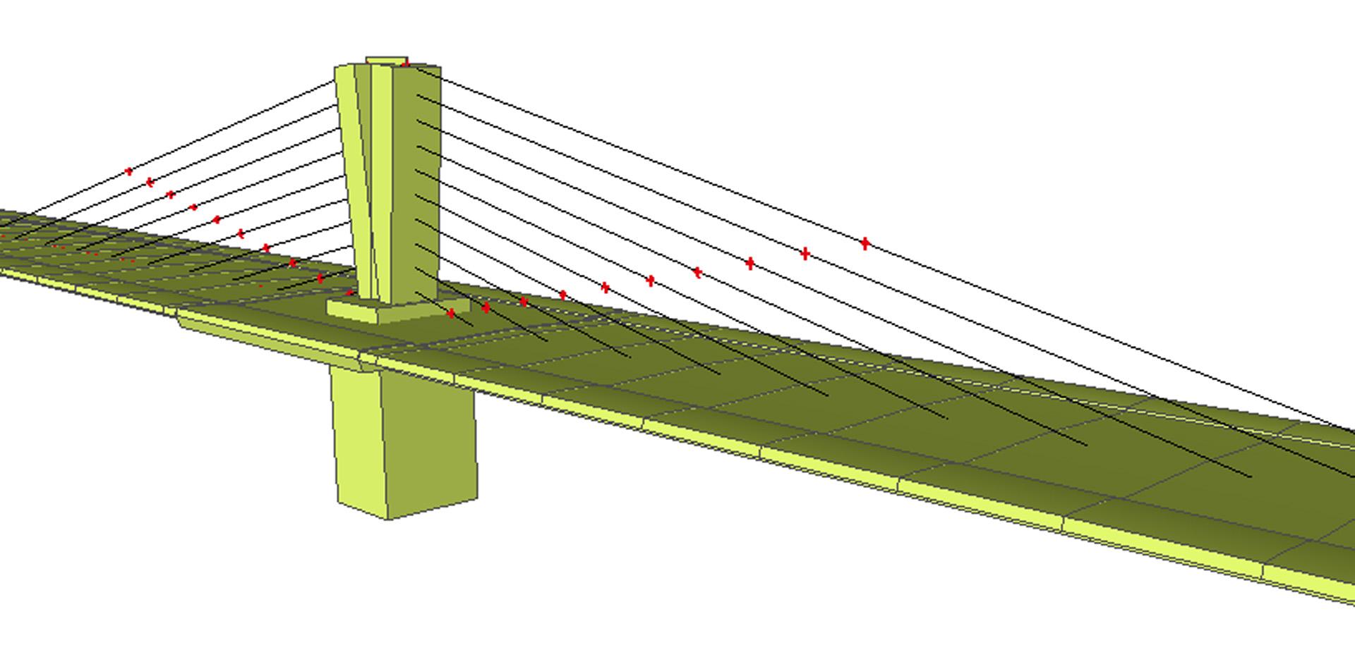
Post-tensioned or external tendons allow the user to model in 3D, and in a practical way, tendons for beams, columns, walls and plates. The user can directly draw an internal or external tendon, or alternatively, he can base the design of a post-tensioned tendon on a library of standard “source” geometries. The source geometry represents a part of the tendon, e.g. the straight part at the end of the tendon, the curved part with the minimum radius above the support or the part at midspan. Source geometries can be merged together to define the practical geometry of the tendon in accordance with a common engineering practice. Tendon geometries can be also easily imported from XML, DWG or DXF files.
During the design, i.e. prior to calculation, the user can quickly review the estimated losses, which attributes to a quick and practical design. After a successful calculation, all the relative geometry data and tendon properties can be printed in a user-friendly style. Additionally, all (geometrical) properties of the internal or external tendon can be parameterised, thus contributing to a fast and easy design of repeating or relatively standard prestressed structures.
Tendons can be defined for any type of structure: bridge, slab in a building, wall or beam. The following codes are supported: IBC, DIN, ÖNORM, ČSN, NEN, ENV and the latest EN code. The tendon can be curved in the XZ-plane and/or XY-plane. Consequently, the user is capable of modelling almost any prestressed structure, whether with or without internal or external tendons.
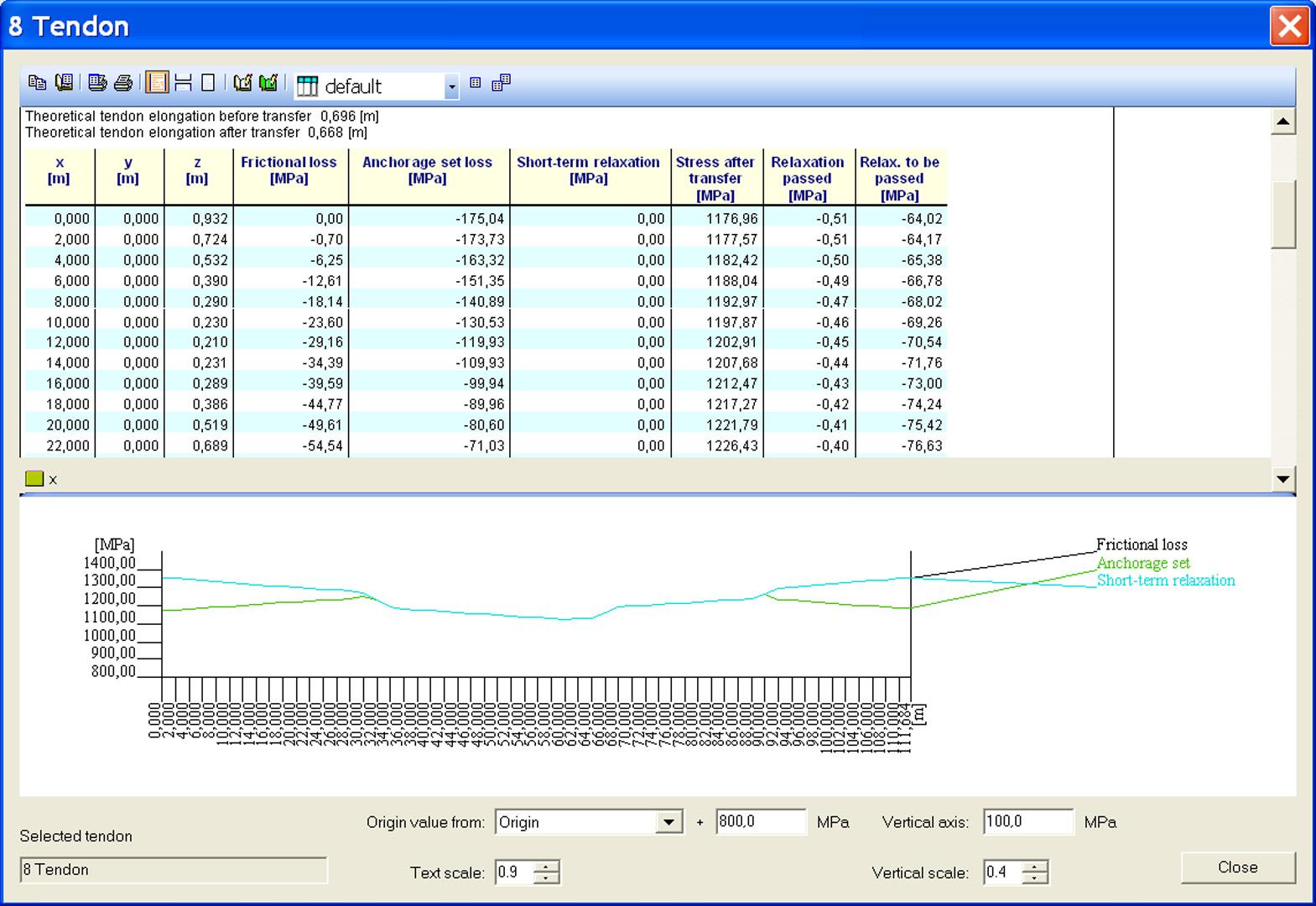
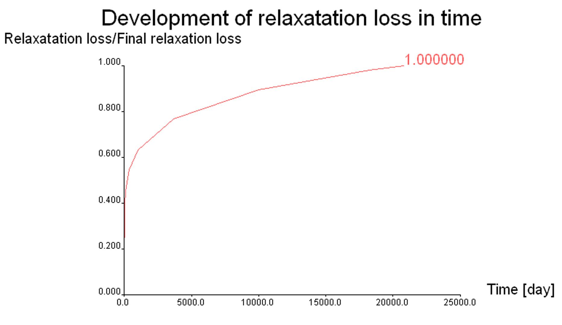
The user can define all the necessary properties of the tendon, such as the anchorage set, initial stress, friction properties, etc. Moreover, the user can specify the method of stressing (only from the beginning, from the beginning and re-stressed from the end, etc.), and the type of short-term relaxation. Usual prestressing materials/elements like wires, strands, cables and bars are defined in the default material library. Common relaxation tables are defined by each national code and can be adapted according to the user’s or manufacturer’s requirements.
When the design of the tendon is complete, the user can export the tendon to a CAD-program for the finalisation of the drawing. The calculation document plots all necessary data, results and properties of the tendon. All relevant data are embedded in the user-perfect document of SCIA Engineer and require no extra handling at all.
The application of post-tensioning together with the module for parameterisation enables the user to define perfect templates of post-tensioned structures in an easy, practical, project-defined or company-defined way. The document meets the engineer’s wishes or practice. Moreover, each individual document can be adjusted separately to meet the requirements and needs for each external party. This is all changed on a click of a button.
Time Dependent Analysis (TDA)
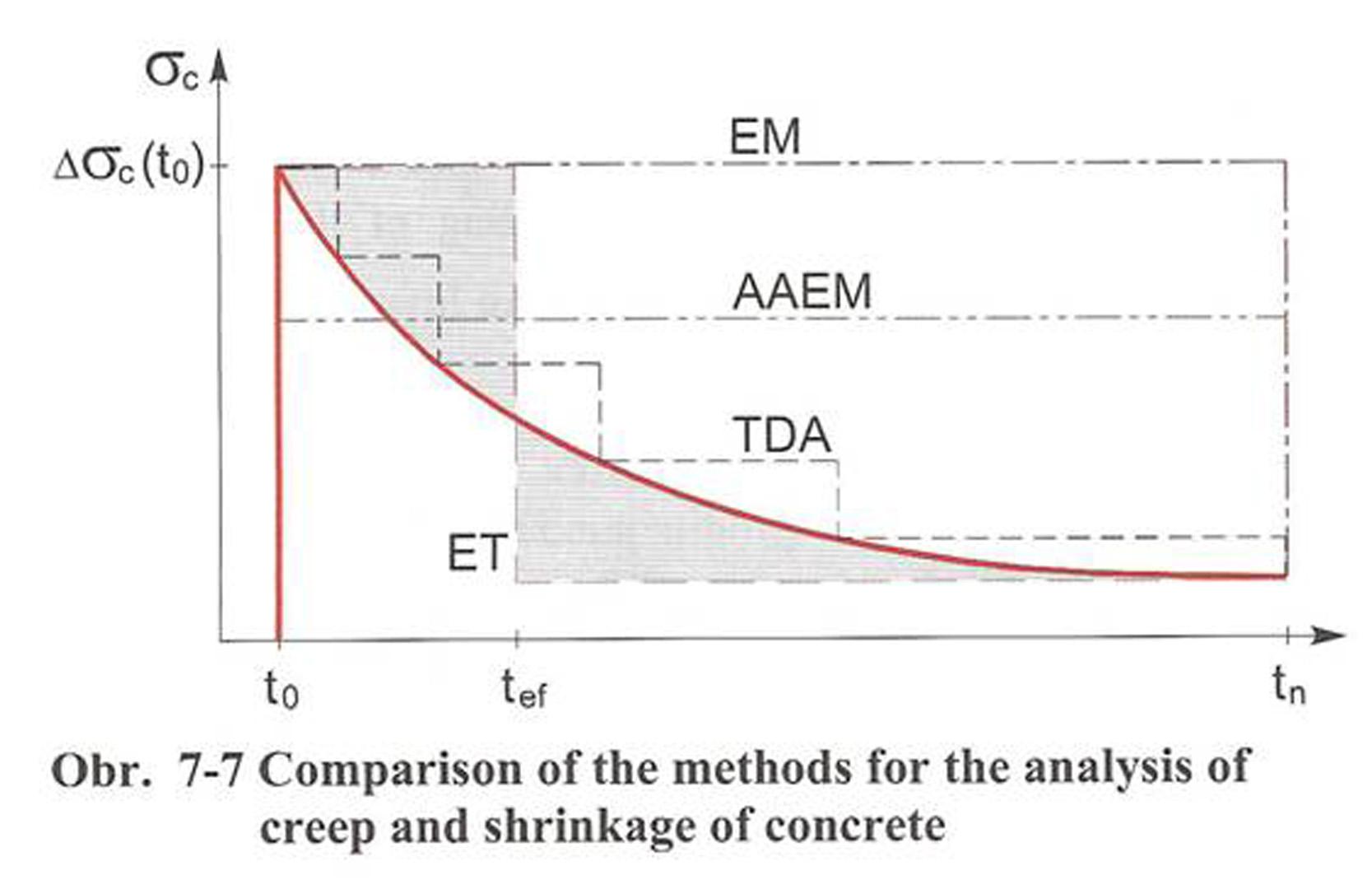
Time Dependent Analysis (TDA) allows for the time dependent analysis of prestressed concrete, but also composite 2D frame structures, while taking into account the defined stages of construction, creep, shrinkage, and ageing of concrete. The method used for the time-dependent analysis is based on a step-by-step procedure in which the time domain is subdivided by time nodes. The finite element analysis is performed in each time node. Linear ageing viscoelastic theory is applied for the creep analysis.
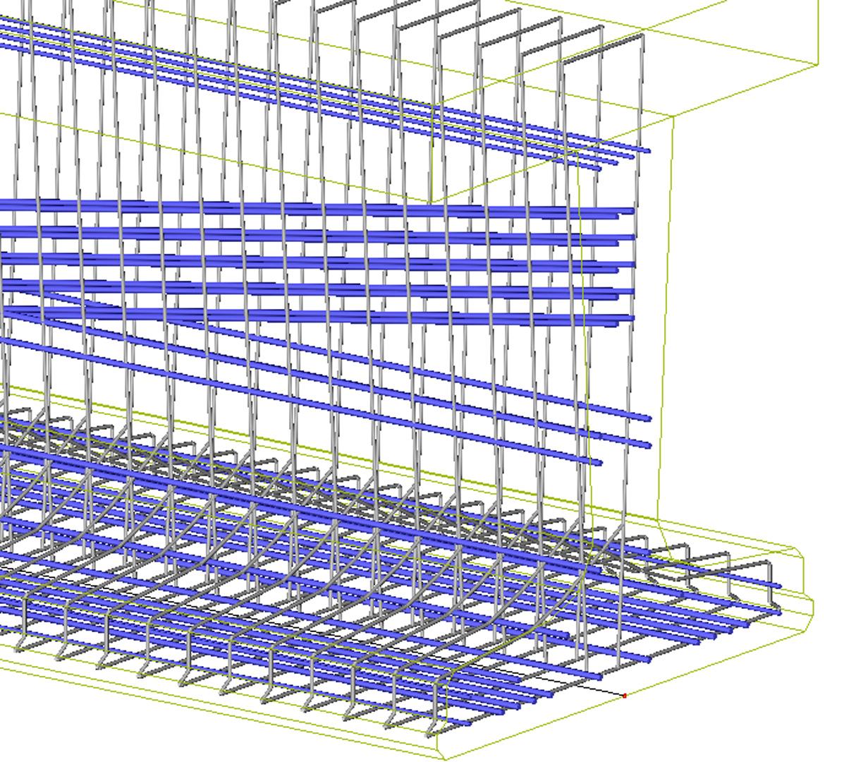
Due to symmetry of the long-term loads both the structure and the load can be modelled in a vertical plane. The plane frame structural model is used. The finite elements on eccentricity represent e.g. the concrete box girder (or separately concrete webs and layers of deck), prestressed tendons, diaphragms, piers, temporary anchoring ties, non-prestressed reinforcement, etc. All operations in the construction are respected in the structural analysis respecting the real production schedule. The elements are installed or removed based on the construction process. Various operations used in the construction such as installation or removal of segments and prestressed tendons, changes of boundary conditions, loads and prescribed displacements may be modelled.
The prestressed tendons are assumed also as eccentric finite elements. When they are initially stressed, only load terms of the tendons are included in the global equilibrium equations. After anchoring, the additional stiffness of the tendon is considered. Both, the bonded and unbonded tendons may be modelled. The long-term losses are automatically included in the analysis. If any element is removed or boundary condition is changed, the internal forces of the element and the appropriate reaction are automatically added to the load vector increment.
The total strain of concrete at a given time is subdivided into three parts:
- stress-produced strain,
- shrinkage and
- thermal expansion.
Neither shrinkage nor thermal strains are stress dependent. The shrinkage of structural members is predicted through the mean properties of a given cross-section taking into account the average relative humidity and member size. The stress-produced strain consists of elastic instantaneous strain and creep strain. The development of modulus of elasticity over time due to ageing is respected. The creep prediction model is based on the assumption of linearity between stresses and strains to assure the applicability of linear superposition. The numerical solution is based on the replacement of Stieltjes hereditary integral by a finite sum. The general creep problem is thus converted to a series of elasticity problems. The creep calculation is also based on the mean properties of a given cross-section. The creep, shrinkage and ageing effects may be taken into account according to design recommendations
- EUROCODE 2,
- ČSN 73 1201 and ČSN 73 6207,
- ÖNORM B4700,
- DIN 1045-1,
- NEN.
The method respects stress history and does not require any iteration in single step and does not restrict the type of creep function.
Implementation of construction stages and TDA
TDA is closely linked to the analysis of construction stages in SCIA Engineer. The difference is that the rheological effects are not considered in the analysis of construction stages. On the other hand, "the load-case" and "the combination of load-cases" are the basic "building units" for both TDA and analysis of construction stages. The analysis of construction stages in fact runs independently on time. It is only a matter of form that each stage is linked to a time node.
The increments of dead load in each building stage (construction or service) and the results (the increments of internal forces and deformations caused by this load) are stored in separate load-cases. This load is assumed to be present (applied on the structure) until infinite time. The unloading must be modelled as a new load with opposite sign. For example - the total internal forces in existing structural members caused by dead loads after third building stage are obtained as the results of the combination of three appropriate load-cases. A load-case representing the life load can be added to this combination.
If any prestressing is applied in the building stage, additional permanent load-case must be applied. Then two permanent load-cases are defined in one building stage – one for the dead load and one for prestressing. The user is not allowed to add loads to prestressing load-case.
One additional (empty) load-case is generated automatically in each construction stage in the TDA analysis. These load-cases are used for storing of the increments of internal forces and deformations caused by creep and shrinkage calculated during passed time interval. They are marked as creep-load cases in SCIA Engineer.
A few practical applications of the module:
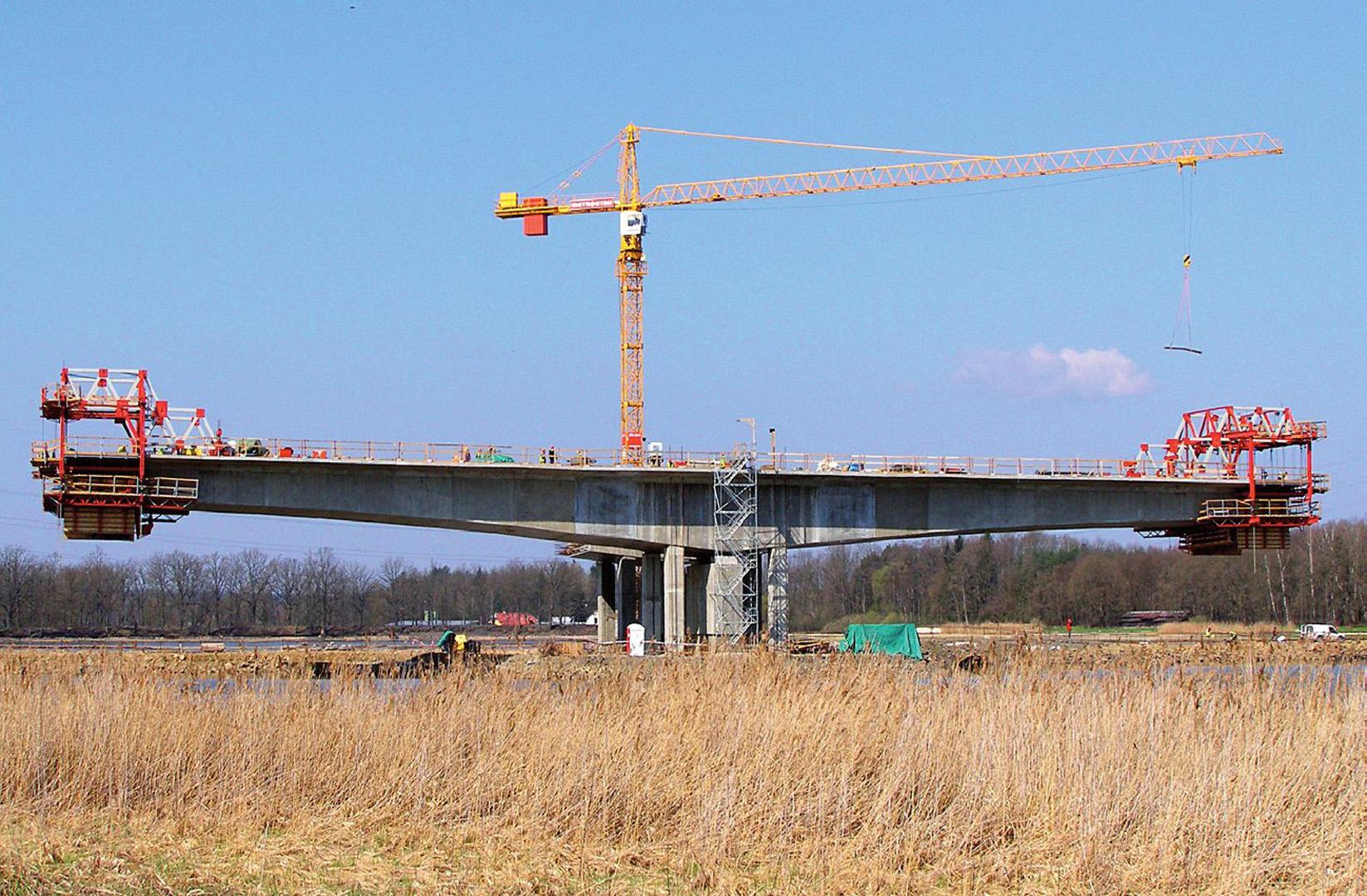
- Wisconsin Avenue Viaduct in Milwaukee, Wisconsin, USA, by CH2M Hill, Milwaukee, Wisconsin with collaboration of Charles Redfield and Prof. Jiri Strasky.
- Precast segmental structure with replaceable cast-in-place deck slab of a viaduct in Plzen. By Strasky, Husty and Partners, Brno, Czech Republic.
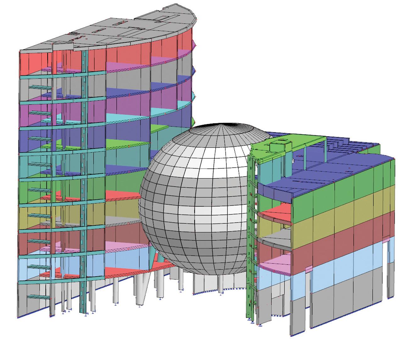
- Gradually prestressed transverse beams in the frame of Sazka Arena in Prague (Ice Hockey World Championship 2004), by PPP Pardubice, Czech republic.
Required modules:
- sen.00

Want to try SCIA Engineer yourself?
Explore how our software and services can help you optimise your work and boost your productivity. Try it for yourself with a free 30-day software trial.
Download a free 30-days full trial