Highlights
- Easy-to-use graphical environment for direct modelling in 3D
- Automated checks and conversions for imported models
- Parametric modelling for repetitive and optimization tasks (available with module “Parametric modelling” scia.m.parametric)
- Analysis and Structural Model integrated in one project to save time and minimize errors in the case of exchange of data with architects/draftsmen
- Library of fabricated and typical sections, integrated designer for a general cross-section (general cross-sections are available with module “General cross-section modeller” scia.m.csseditor)
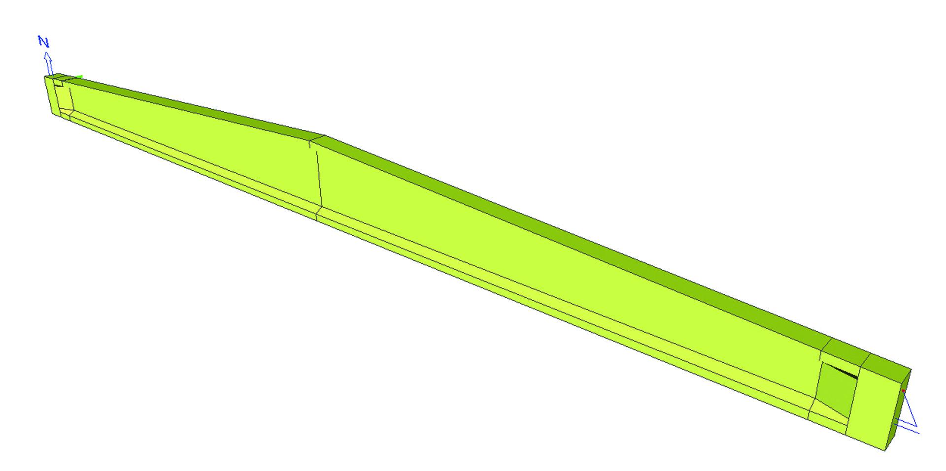
- Beams and columns of any geometry: straight, curved, arbitrarily shaped, with a cross-section varying along the length or with openings
- Auxiliary grids and storeys for more effective work with large models
- Library of predefined structural parts: frame, truss girder, spiral ramps, dome, pipe elbows, etc.
- Picture or Drawing gallery (editing and elaborating drawings with text, dimensions, comments, etc.).
- BIM environment; import/export of geometry to IFC 2x3, VRML, SDNF formats, etc.., IFC 2x3, IFC 4
- Import/export of the model in different formats (reading and writing in PSS, DStV, DXF, DWG, XML, IFC, BMP, WMF, etc.).
- Calculation reports document the input, results, drawings; can be exported to RTF, HTML, PDF and TXT-formats.
- Automatic generation of load case combinations in compliance with national technical standards
- Project templates
- Table Input of project data (for members, boundary conditions and loads)
- Table Results for viewing results in tabular form
Module scia.basic is the basic SCIA Engineer module that allows for free modelling in 2D or 3D environment of 1D members (beams, columns, etc.) including all necessary boundary conditions, such as supports, hinges, eccentricities or variable cross-sections along the beam and application of load impulses. Loads may be applied directly on the beams as point or line loads, or they may be transferred by load panels which distribute the load to individual members or edges. It contains various libraries streamlining the structure definition and preparation of the model for FE analysis. Separate load cases for any load type are available and they may be combined in either automatic EC combinations or in manually created combinations. In this module you can run a linear analysis, investigate and print results in both tabular and graphical form and to compose a project documentation in Engineering Report.
The basic module allows you to easily edit the structure with the help of view parameters, grids and dimension lines, layers, clipping box etc. Images and sketches may be stored in Picture Gallery or PaperSpace gallery or used directly in Engineering Report. A variety of import and export formats is supported, incl. IFC, DWG, XML, etc. Table input and Table results can be used for tabular import and evaluation of the results or for direct exchange of data with MS Excel sheets.
Functions in the scia.m.frame module may be divided to a few groups:
- Modelling 1D elements in 3D space including their boundary conditions
- Applying loads on beams, using load panels to distribute surface loads
- Linear analysis
- Using set of tools for enhanced productivity
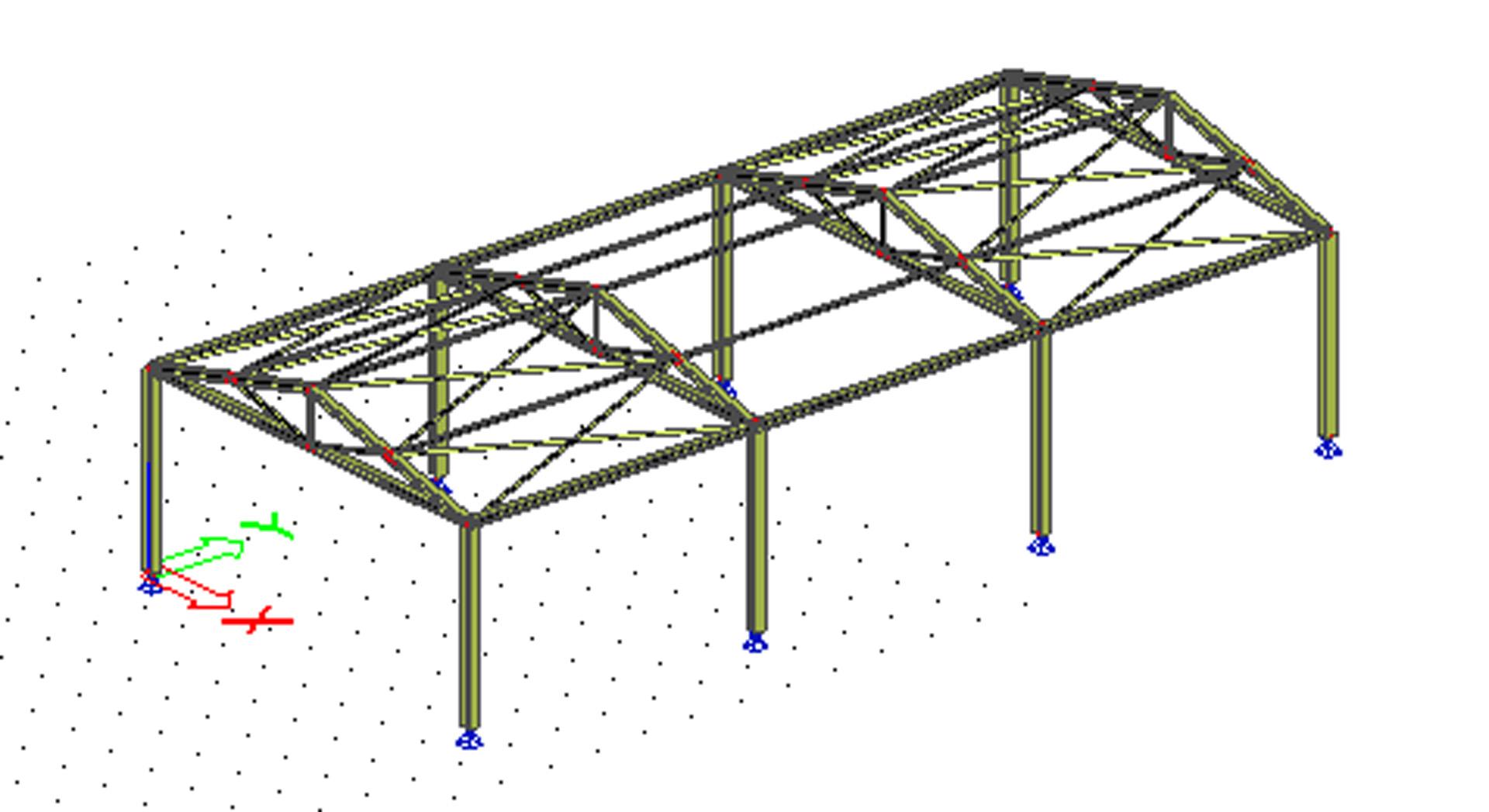
1D member modeller
The module allows for free modelling of 1D members (beams, columns, etc.) in 2D or 3D environment including all necessary boundary conditions, such as supports, hinges, eccentricities or variable cross-sections along the beam. The modeller allows for a complete shape freedom, where straight or curved beams may be created. Members may be either modelled within the interface of SCIA Engineer or imported from external sources.
Graphical user interface
Display
- Zoom scale, adjustable viewpoints;
- Axonometric and perspective projection of the modelled structure;
- Wireframe, surface line, or rendered display of members with several rendering modes;
- Several graphical windows can be opened at the same time - this allows for the simultaneous viewing of different components in the model or viewing from multiple viewpoints;
- The visibility of each defined member is switched to active or inactive; entities can be added to different layers; various options exist for setting visibility - activity by selection, activity by working plane, activity by layer;
- Animation of results;
- The Clipping Box is a rectangular prism that can be placed anywhere in the modelling space. Only modelled entities that are located within the boundaries of the prism will be displayed to the user.
Graphical and numerical
- A CAD-style interface ensures that the user can "draw" his structure on the screen, using simple definition of geometrical shapes;
- grids, rendering and other graphical tools;
- Table input for those who prefer tabular style of work or for those who want to copy externally prepared data from a third-party spreadsheet.
- Input through the command line is also possible.
Property window
The Property window shows contextual parameters depending on the current selection. Any time an entity is selected, all its input parameters including derived properties are displayed in the Property window, where these can be reviewed and/or edited. For example, a new cross-section can be reassigned directly in the Properties window. Changes are at once displayed in the graphical window.
Modelling tools for 1D members
SCIA Engineer offers an integrated Cross-section library with a vast selection of shapes and dimensions:
- Standard steel profiles according to a number of national standards are available - European, American, Russian, Chinese, Brazilian, Japanese, Indian, etc. hot-rolled profiles as well as common cold-formed steel sections from various producers.
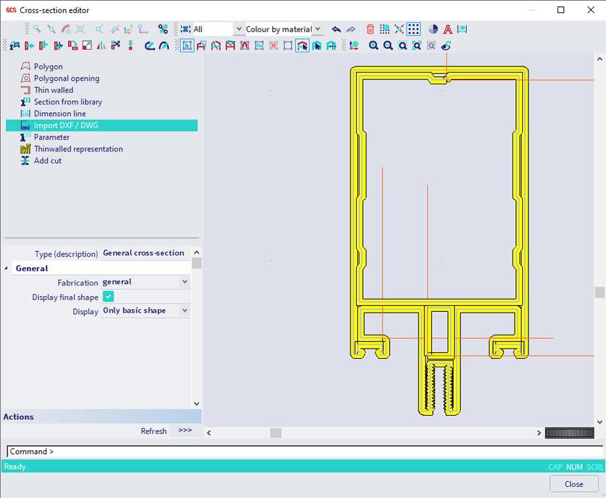
- he available cross-sections can be edited, or new ones can be added, using the General cross-section editor (module scia.m.csseditor). Section characteristics, including torsional/warping properties, are calculated automatically.
- Built-up sections can be compound from the available shapes in the profile library.
- Templates for concrete, composite and precast sections with reinforcement, as wells as timber sections are also provided.
- Common bridge cross-sections, or sections consisting of multiple materials are easily defined by means of a few parameters. Additionally, cross-section parts may be linked to different construction stages (requires Construction stages module sens.20).
- General and numerical sections can also be used;
- Sections can be imported from DXF or DWG formats.
Materials
Material data can be found in the (editable) Material Library of SCIA Engineer. Extensive lists of steel, concrete and timber materials are available according to many national standards.
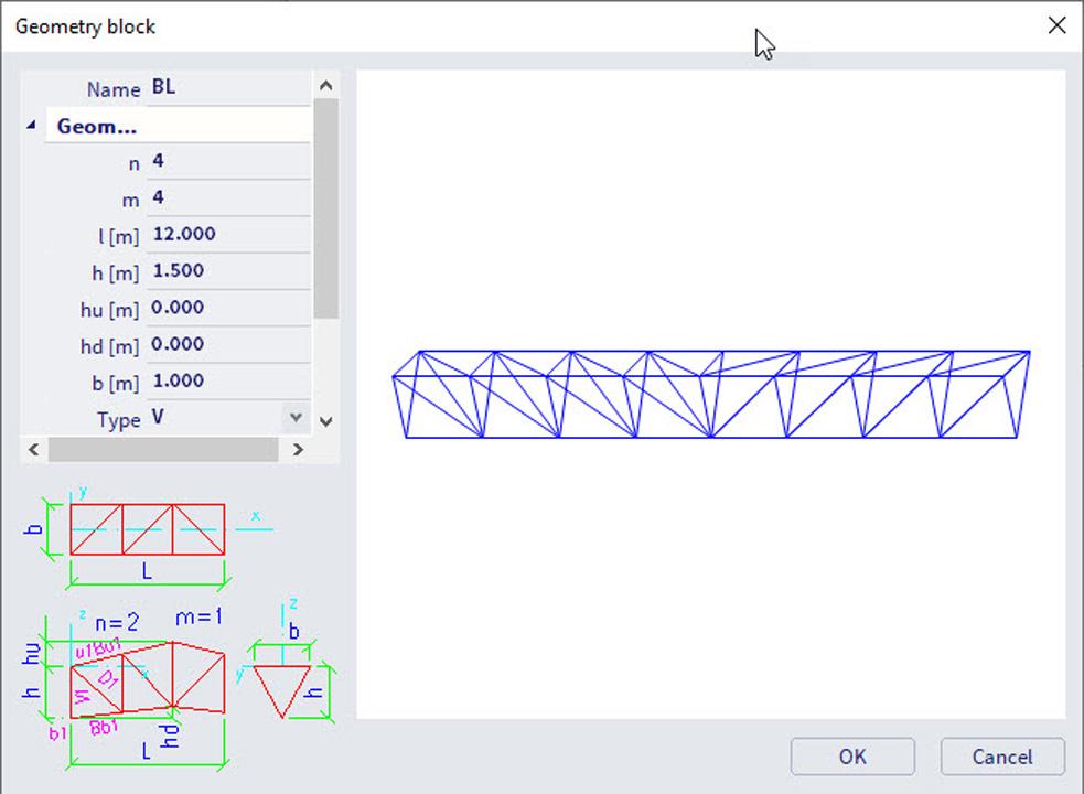
Catalogue blocks
Common structural configurations are available as Catalogue blocks - 2D/3D frames from 1D elements, 2D/3D truss girders, towers, typical curves. The user is able to add new blocks or edit existing ones.
Units
The user selects to work in metric or imperial units. The units of individual properties are independent from each other - it is possible to define the geometry in metres, display calculated displacements in inches, and have dimension lines of connection drawings in millimetres.
Coordinate systems and grids
- User coordinate systems and 2D/3D grids are adaptable - these can be positioned as needed.
- Both dot grids and line grids allow for a more organised input by snapping and clear visualisation.
- Line grids are defined as Cartesian, oblique, spherical or cylindrical.
- Several grids can be defined in one project.
- Grids may be switched on and off.
Other
1D members can include openings, haunches, transverse stiffeners, variable sections along their length.
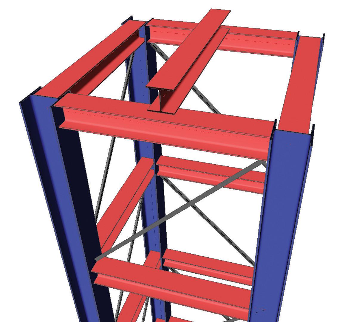
Analysis and Structural model
The analysis model contains just enough information to perform the analysis - beam geometry and section, material and load data and boundary conditions. SCIA Engineer allows the engineer to quickly define the relation between the analysis model and the real shape of the structure (contained in the Structural model).
The advantages a structural model:
- It ensures consistent communication with CAD-software and guaranties the integrity of the Building Information Modelling process;
- The structural model may contain entities that are not going to be taken into account during the analysis (banister, windowpanes, etc.). A structural model can be created from the analysis model and vice versa (see topic Structure2Analysis);
- Full control of changes made by different teams working on the same project - architects, engineers, contractor, etc;
- Automatically generated general arrangement drawings.
Load Panels and Plane Load Generator
Load panels and plane loads are non-structural elements that transform surface loads to line and point loads on structural elements (1D and 2D members).
Plane loads or load panels can represent:
- wall and roof sandwich panels with insufficient stiffness,
- roof/wall windows subjected to wind or snow,
- wind and snow loads on framed structures or structures without modelled envelopes.
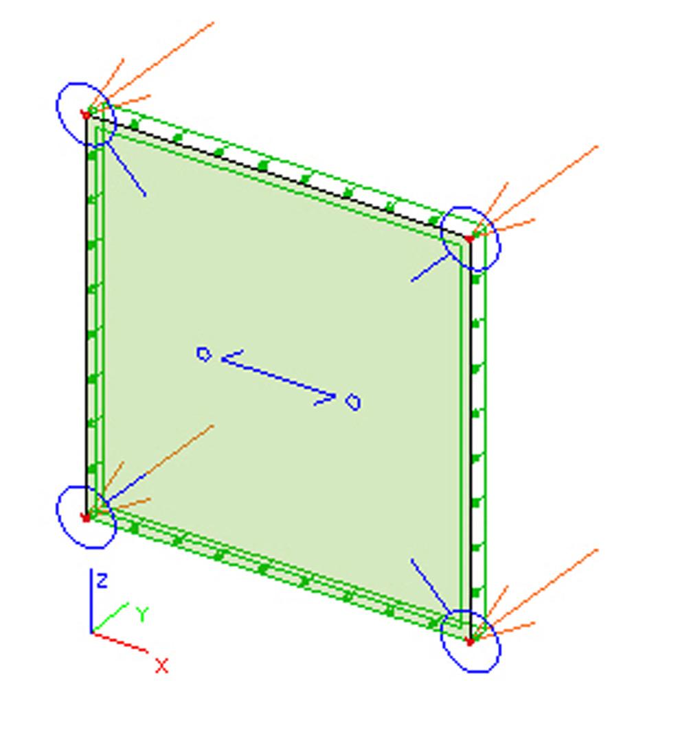
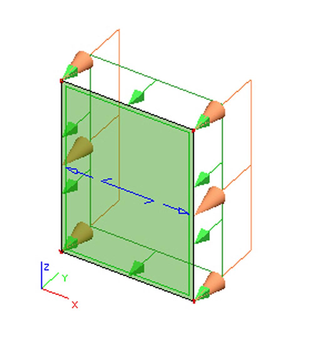
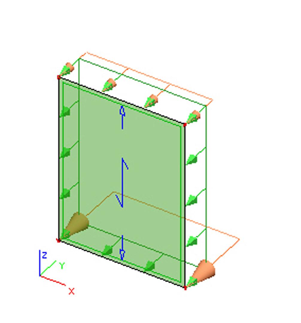
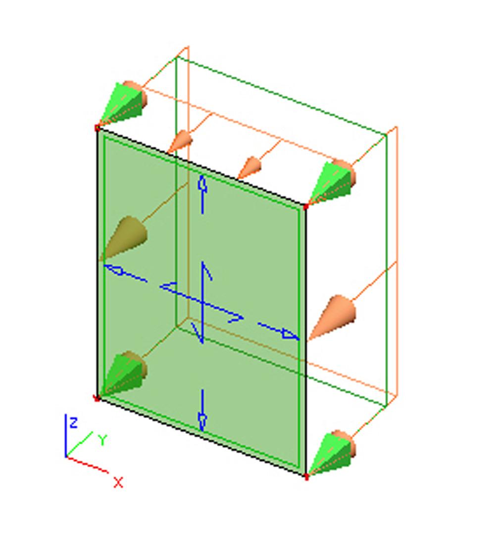
Load Panels
Load panels offer advanced way to distribute loads from surfaces that do not bear any load or that do not affect the stiffness of the structure. Load panels are required for the definition of 3D wind on frame structures (without load bearing walls). Load panels remain editable after the load redistribution. The calculation always reflects the current properties of the load panels. Panels are suitable for a wider range of applications than the Plane Load Generator.
Load panel types
Load Panels distribute the applied loads to entities that support them. Such entities can be (i) nodes, (ii) edges (e.g. opening edges), or (iii) beams in the plane of the panel:
- A Load panel of type "Load to panel nodes" transfers the applied load to all or to selected panel nodes (panel node is a node defining the panel geometry).
- A Load panel of type "Load to panel edges" transfers the applied load to all or selected panel edges. Edges must be supported by beams or edges of 2D members.
- A Load panel of type "Load to panel edges and beams" transfers the applied load to all or to selected edges. In this case, a more accurate method can be used to determine the path of applied loads - a FEM analysis is performed to determine the load distribution.
- Load panels may have openings. Internal edges at openings can also be used to take up loads (if beams are defined there).
The first two panel types distribute the load to participating nodes or edges uniformly, taking into account the edge lengths or number of nodes. However, the user can adjust the weight of individual edges or nodes so that these take up relatively larger/smaller portions of the load.
Additional features
- Load panels are available in all project types.
- All load types can be used on the panel - free point load, free line load and free and normal surface load, wind and snow loads, etc.
- The loads on the panel may act in any direction.
- Supporting nodes and edges of a panel can be displayed.
- The resistance and stiffness of load panels are not considered in the analysis.
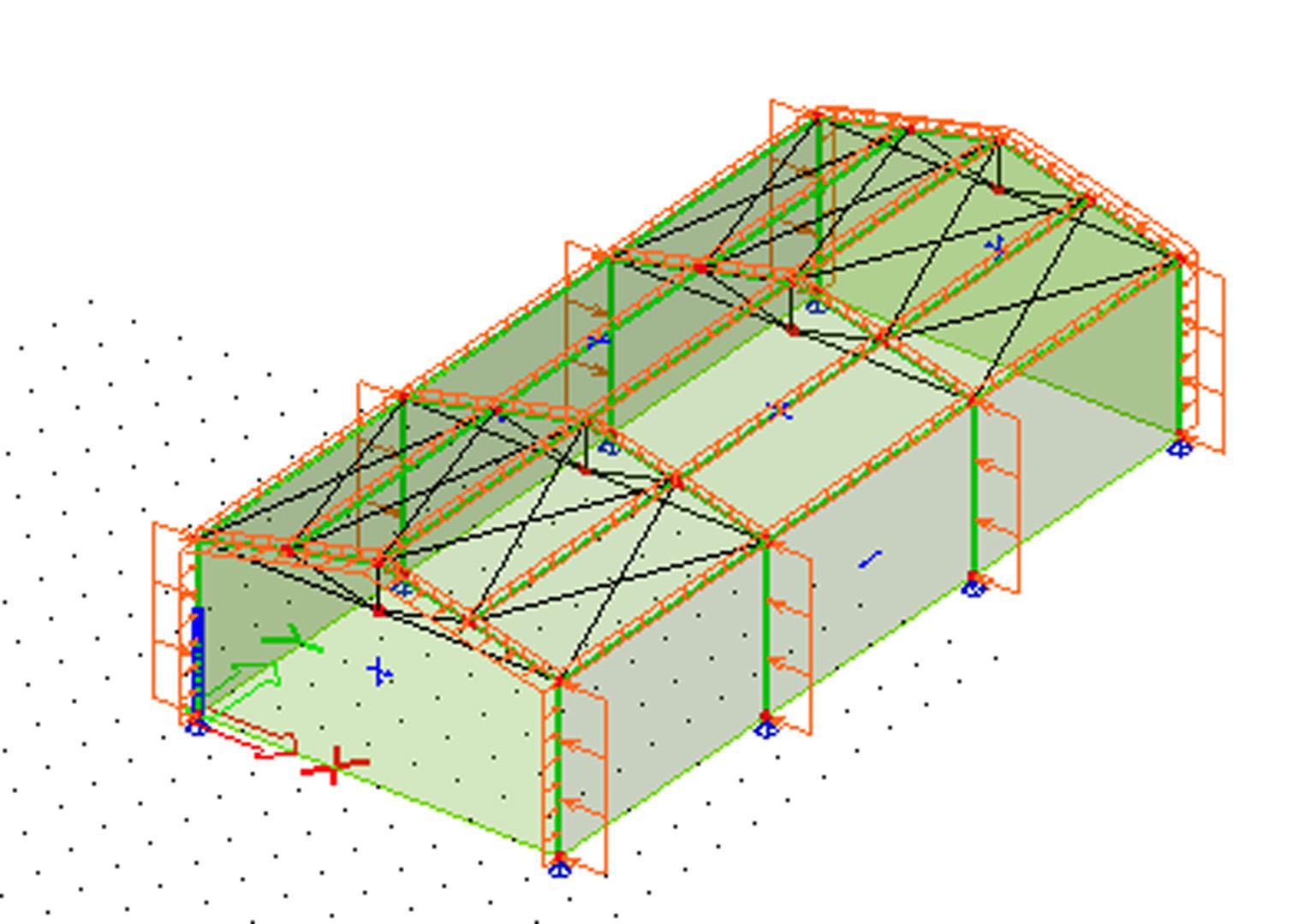
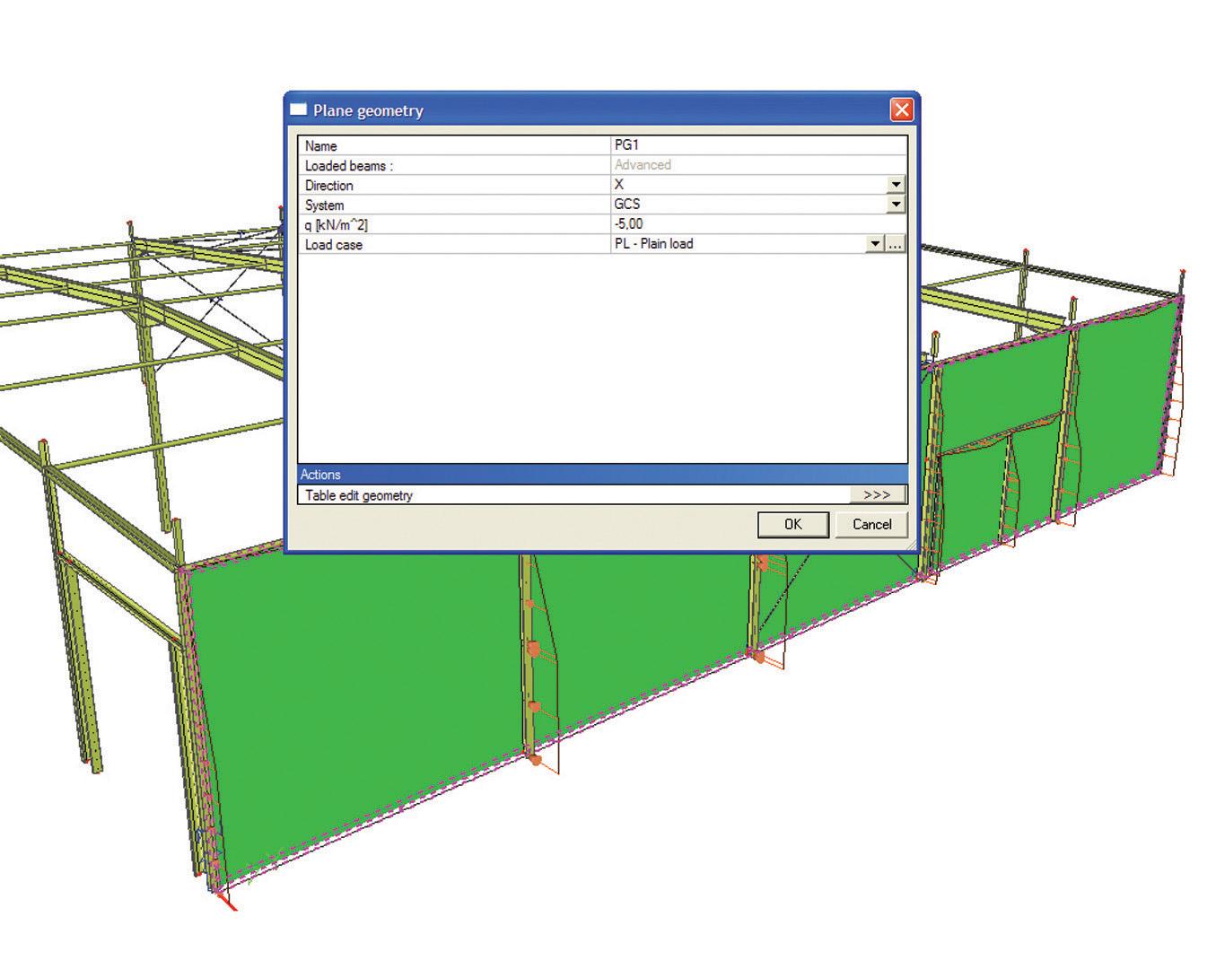
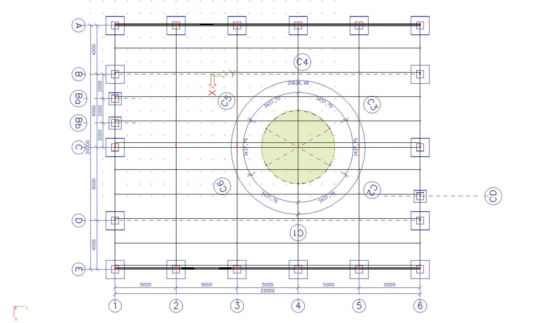
Plane Load Generator
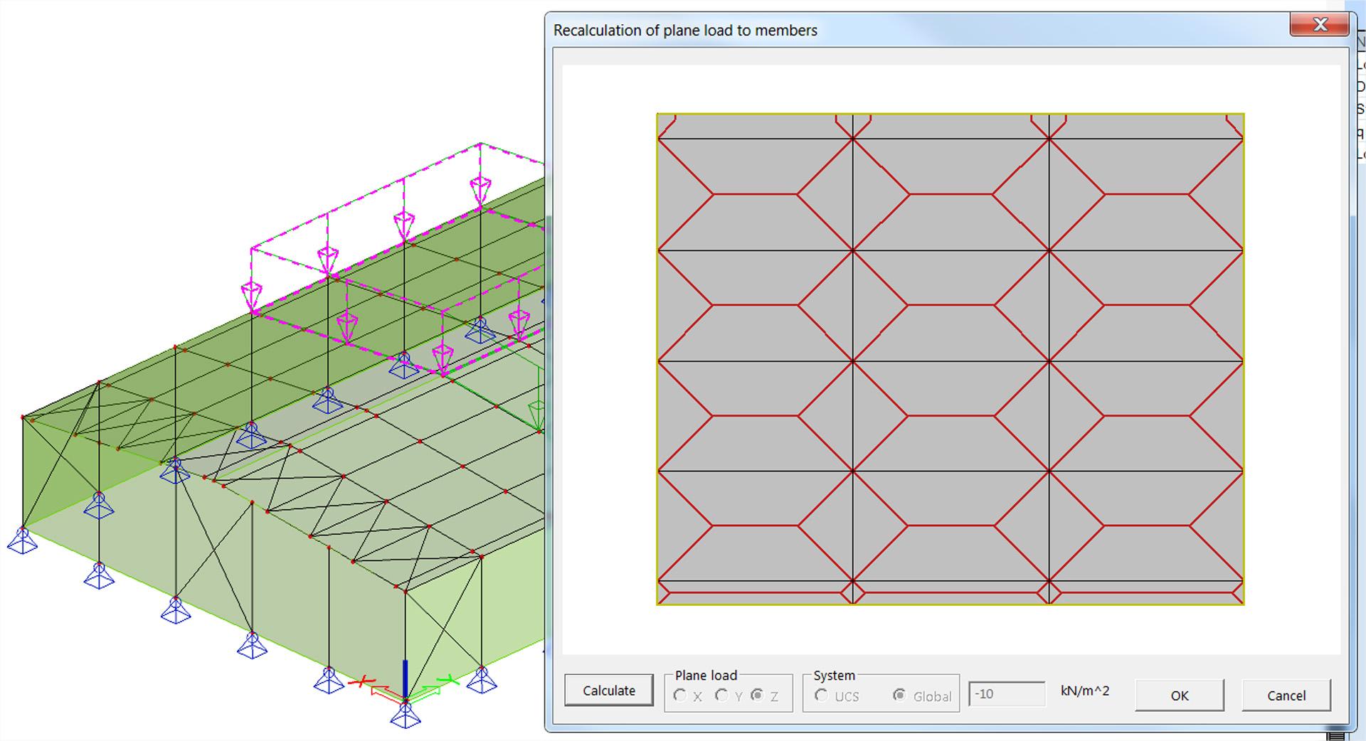
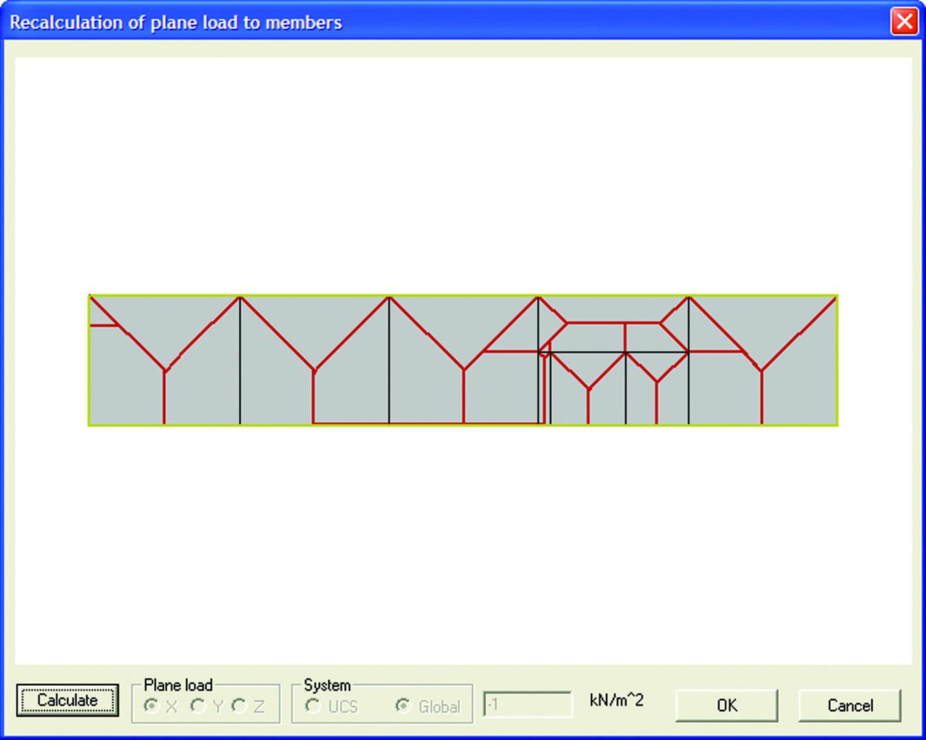
The Plane Load Generator converts surface loads to line loads on supporting beams. The Generator creates 2D planes which serve only to transfer the load to 1D elements and do not alter the stiffness of the structure.
Features
- The load plane is input graphically in the 3D window of SCIA Engineer;
- The surface load may act in any direction;
- The shape of the load plane may be rectangular, circular, or a general polygon with straight or curved edges and may contain openings of any shape;
- The user can select which beams in the loading plane will take up the load and leave other beams unloaded;
- Plane loads remain editable after the load redistribution. The calculation always reflects the current definition of the loading polygon.
Limitations
- 1D members that take up the load must be located in the loading plane.
- The loading polygon (shape) must be planar.
Analysis summary
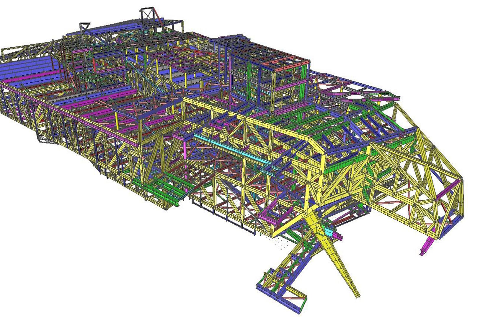
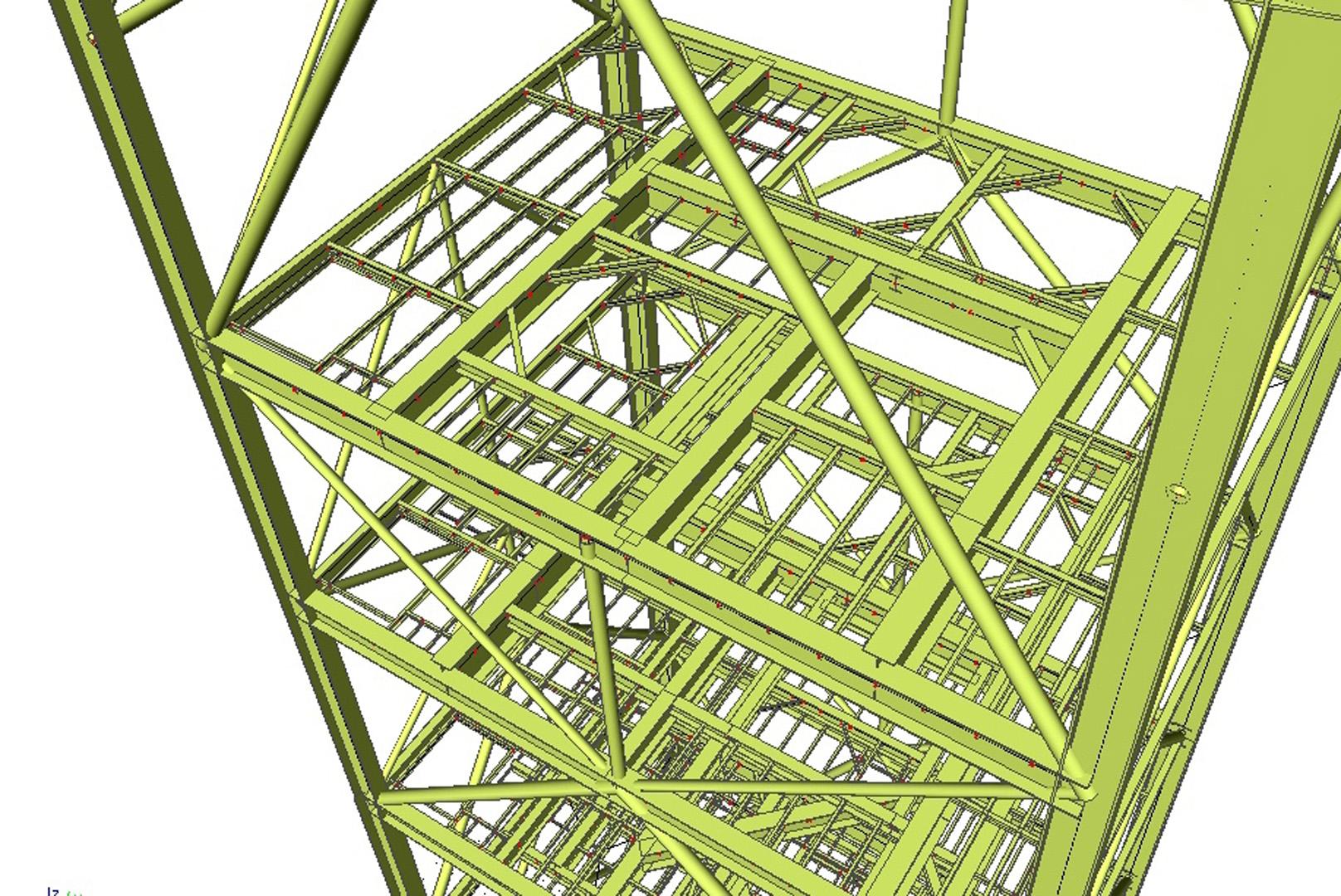
SCIA Engineer analyses all kinds of structures from various sectors:
- Buildings: apartments, high rise buildings, housing, offices, roof systems, curtain walls, glass structures, winter gardens…
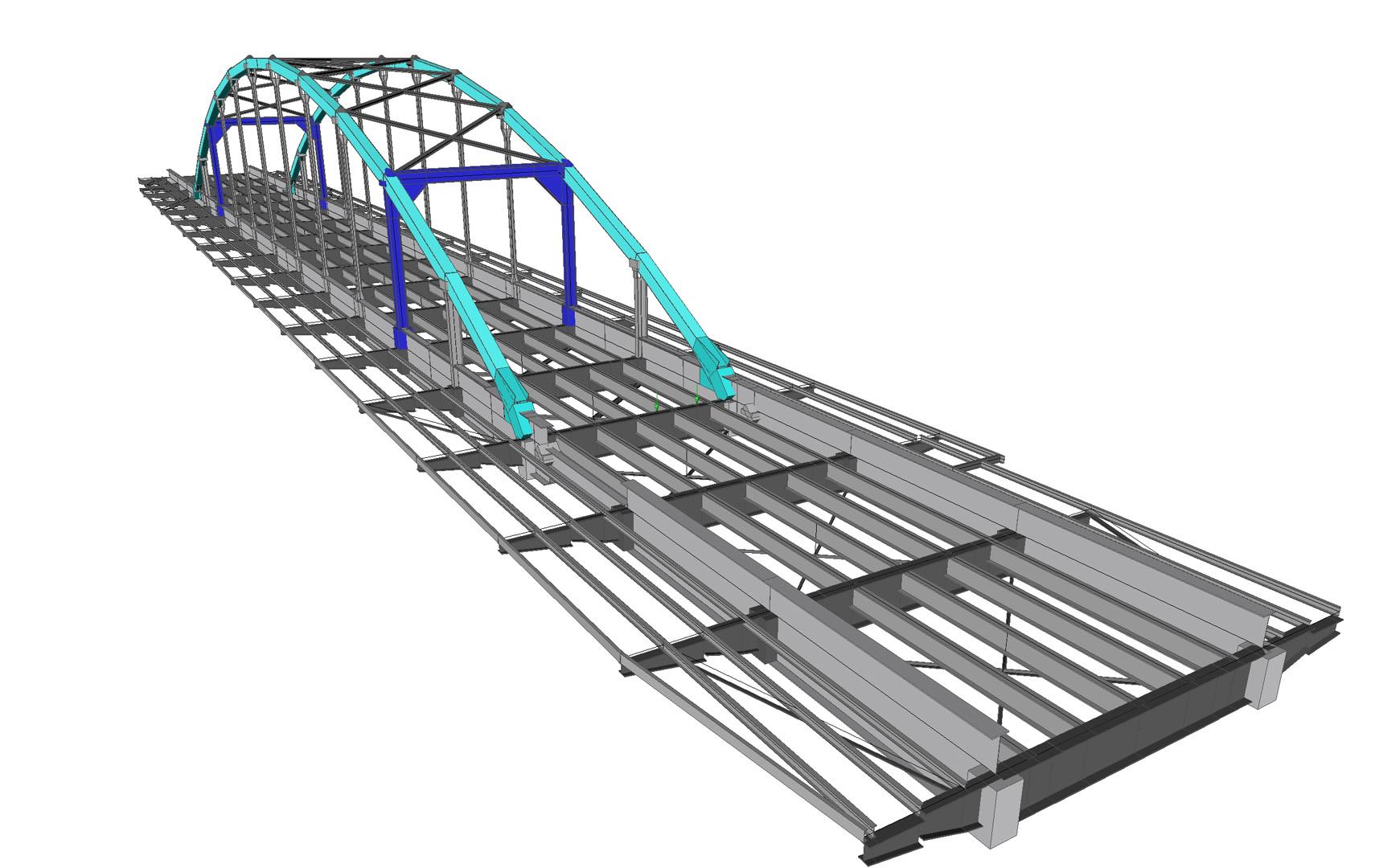
- Infrastructure: bridges, train stations, airports, car parks, stadiums, theatres…
- Industrial buildings: portal frames, storage buildings, maintenance workshops…
- Mechanical industry: pressure vessels, pipelines, load bearing structures…
- Environmental: water treatment and soil purification plants, containment vessels, tanks…
- Harbour construction: quays, lock doors, shutters…
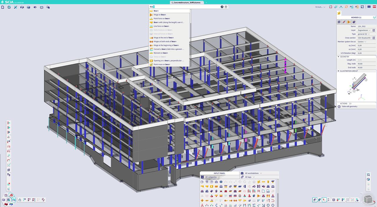
- Prefab concrete structures: plate decks, slabs, walls, girders and columns...
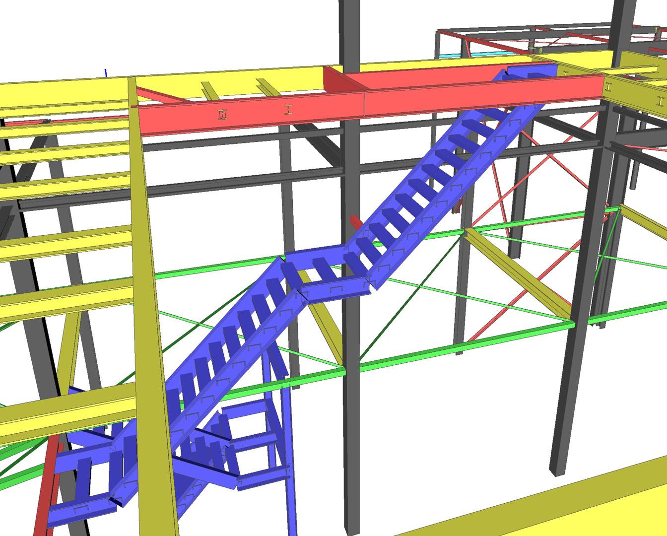
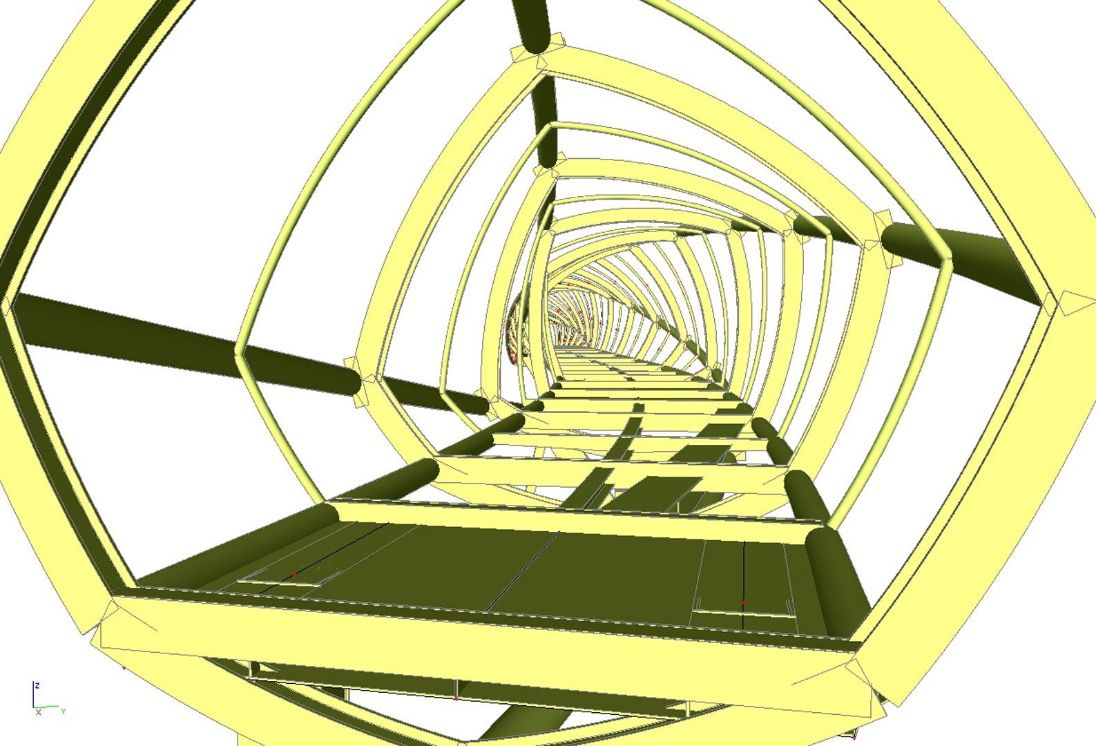
- Specials: transport installations, plants, cranes, masts, towers, scaffolds, stairs and other structural parts.
- Soil-structure interaction, underground structures: tunnels, excavations, metros...
Linear analysis of 1D members
Linear calculation in SCIA Engineer offers a professional tool for analysing two- and three-dimensional beam structures made out of steel, concrete or other materials. The program links the results from the steel and concrete structure analysis to various code checks.
- Linear static calculation of structures with members and/or plates (finite elements) loaded in the plane (e.g. frames, walls) or perpendicular to the plane (e.g. grids, floor slabs).
- Includes modelling and analysis of supports (fixed or hinged in nodes, on members and on plate borders), internal hinges in members and between plates, rigid connections, eccentricities, variable profile sections, variable plate thickness, etc.
- Load types: dead weight, nodal and concentrated loads, uniformly distributed and triangular loads, uniform or live loads, support displacements, temperature (uniform and gradient), etc.
- Automatic load combinations depending on the chosen standard, but user-defined combinations as well are possible.
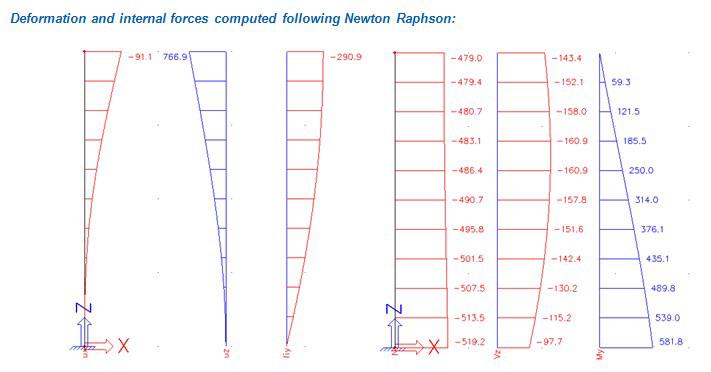
- Results: numerical and graphic representation of displacements, support reactions, internal forces and stresses.
- Graphic representation with perspectives, cuts, details, isolines and isobands. All tools of the basic modules are available.
- Simplified user interface for simpler models such as plane frames with loads only in the structure plane or grids with loads only in the plane perpendicular to the grid plane.
Model
The user has access to a wide range of elements to generate an accurate model of the structure. These include:
- Beams and slabs (modelling of slabs and shells requires module scia.m.surface);
- Fixed, hinged, rolling and elastic point and line supports;
- Hinges in beam and slab connections (hinges on planar elements require module scia.m.surface);
- Rigid links between nodes of the structure;
- Eccentricity of individual beams and slabs;
- Foundation blocks and strips on elastic subsoil;
- Haunches and arbitrary profiles;
- Variable thickness of slabs and ribs (modelling of slabs and ribs require module scia.m.surface).
Load
Users can apply the following types of loads:
- Self-weight. The program automatically calculates the applied load according to the beam cross-section and the material;
- Concentrated force and moment loads;
- Uniform or trapezoidal distributed force and moment loads on beams;
- Distributed loads on slab edges (loading of slabs require module scia.m.surface);
- Surface load on slabs (loading of slabs require module scia.m.surface);
- Eccentric load;
- Support displacement (settlements) and rotations;
- Temperature load (uniform or gradient);
- Absences of members and supports in certain cases (to simulate construction phases);
- Loads calculated from given layer composition of e.g. for floors;
- Climatic loads caused by wind pressure and snow weight.
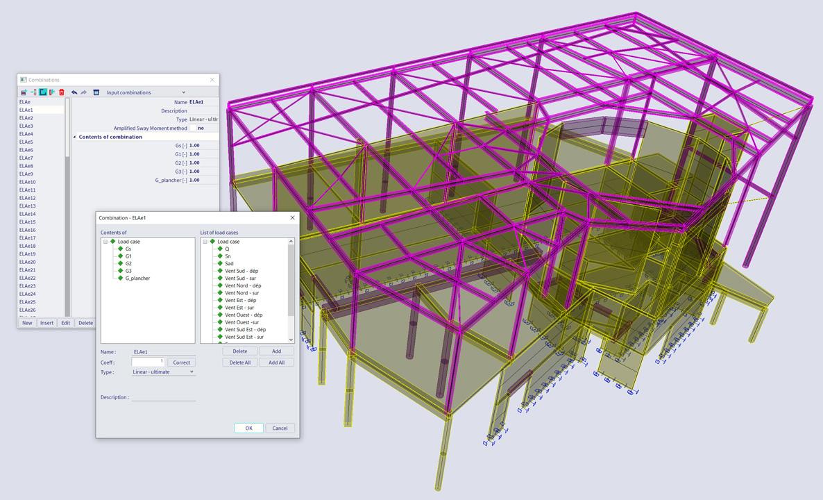
Load combinations
The program can automatically generate design code combinations (EC, DIN, NEN, ÖNORM, SIA, ČSN, etc). The user can also define his own combinations if required.
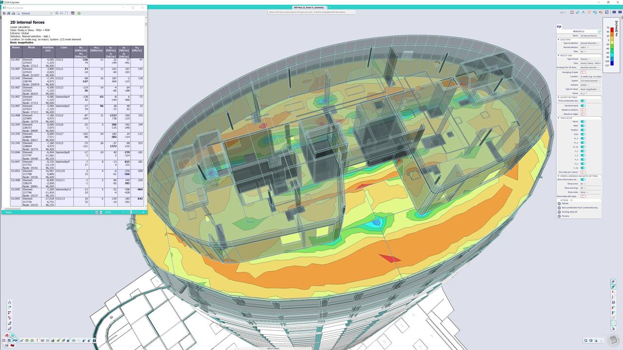
Clear and detailed results
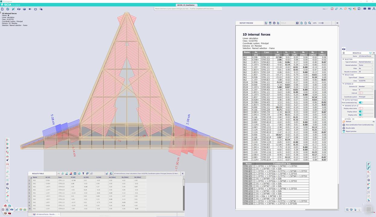
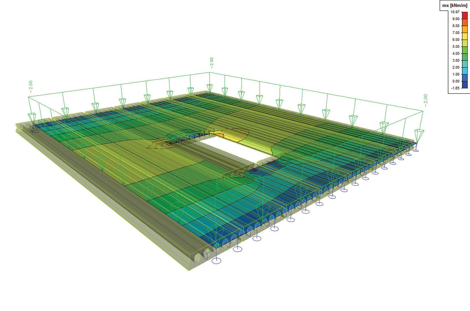
- Diagrams on the model: diagrams of result values drawn on the model in 3D graphical window
- Resultants: loads, reactions, forces in sections
- Detailed results on separate members: detailed evaluation of results and diagrams member per member
- Comprehensive report about the calculation
- Engineering Report: combination of tables and pictures in a structured report
- Table Results: all results values in a tabular form (with an optional export to MS Excel)
Comprehensive results
Beams and columns:
- diagrams
- resultants
- local and global extremes
- results on beams in user-defined fibres
- redistribution of bending moments
Sequential Analysis
In sequential analysis you can select a predefined sequence of different calculations, where the second one starts from the results of the first one. This means that the results from the first analysis are taken as the initial state for the second one.
The sequential analysis gives experienced users the possibility to obtain results that are not available through a single analysis. Two different types of sequential analysis are available.
The first type is a superposition of two different methods of calculation (e.g. linear + non-linear calculation). In other words, results of both calculations are added up. This is done for a non-linear combination that can be combined with a linear combination.
Second, the phased type is offered. This means that the second analysis starts where the first one ends; it takes the history of the structure into account. For this type, several couples of analyses are possible:
- Linear stability calculation after a non-linear calculation
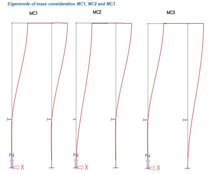
- Dynamic calculation after a non-linear calculation:
- An eigenmode calculation that takes non-linearities into account
- A harmonic calculation that takes non-linearities into account
- A seismic calculation that takes non-linearities into
Productivity toolbox
The Productivity toolbox provides a number of powerful tools to enhance user's productivity.
Project templates
SCIA Engineer enables for the definition of project templates from existing project files (.ESA files). Project templates contain preferred material data, cross-sections, standard load cases, combinations and Engineering Report layouts. Using templates, one saves an entire project and work environment into templates (materials, frequently used profiles, structural norms, load cases/combinations, calculation reports, etc.).
- Any SCIA Engineer input data can be configured in a project template.
- The user does not need to create calculation reports from scratch for each new project.
- Analysis of routine structures is more efficient - in combination with module “Parametric modelling” scia.m.parametric, powerful project templates may be created. When template is loaded, it requires minimal user input in order to execute the design.
- Companies often establish standardized project templates and distribute these among their employees for efficiency when starting new project.
Table Input
The Table Input functionality allows for the dynamic input and editing of project data. A bi-directional link between the model and input tables allows for:
- The properties of all existing entities in a model to be listed in a tabular form;
- Entities to be updated according to changes made in input tables.
- New entities may be inputted by copying them from MS Excel and pasting them into Table Input.
Table Input has these characteristics:
- The Table Input window may be displayed simultaneously with the 3D model..
- New members, loads and supports can be defined directly in Table Input.
- Changes typed in the input tables lead to immediate regeneration of the model.
- Model data generated in any other way are also displayed in the Table Input window - this allows for editing of existing elements, boundary conditions and loads.
- Batch changes can be done in MS Excel or other spreadsheet applications (copy-pasting is enabled).
- Table input offers filters for activity and selection, sorting or filtering of data based on content of any column.
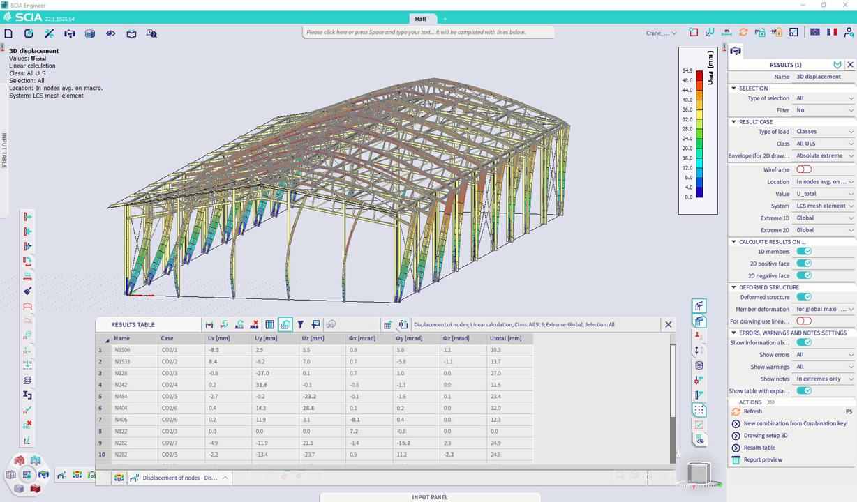
Table Results
Table Results list calculated results in a tabular form. Table Results display a wide range of calculated items, including FEM results for nodes, 1D and 2D members, the results of design checks, and others. As soon as a calculation is performed and results are available, Table Results are filled in with the values of internal forces, displacements, calculated areas of reinforcement etc..
The advantages of Table Results include:
- A link to the Windows clipboard;
- Sorting of results depending on a wide range of criteria (e.g. ascending / descending / alphabetical order in columns);
- Filter fields in each column make it possible to display only the result items that meet a certain set of criteria;
- Full control on the display of properties and visibility of columns for each result type;
- The edited layout of tables can be saved and later loaded on the same PC or layouts may be shared between PCs;
- Table Results allows using filters for activity and selection, sorting or filtering of data based on content of any column.
The active result type currently displayed in the Table Results window is fully decoupled from the 3D Graphical Window. In this way, the user may review one type of result in the tables, and another type in the Graphical Window.
Standardised modelling tools
Ribbed slabs
This function allows the user to quickly input a plate with several stiffening ribs.
Prefab slabs - 2D to 1D upgrade
2D-1D Upgrade is a special export functionality for prefabricated slabs.
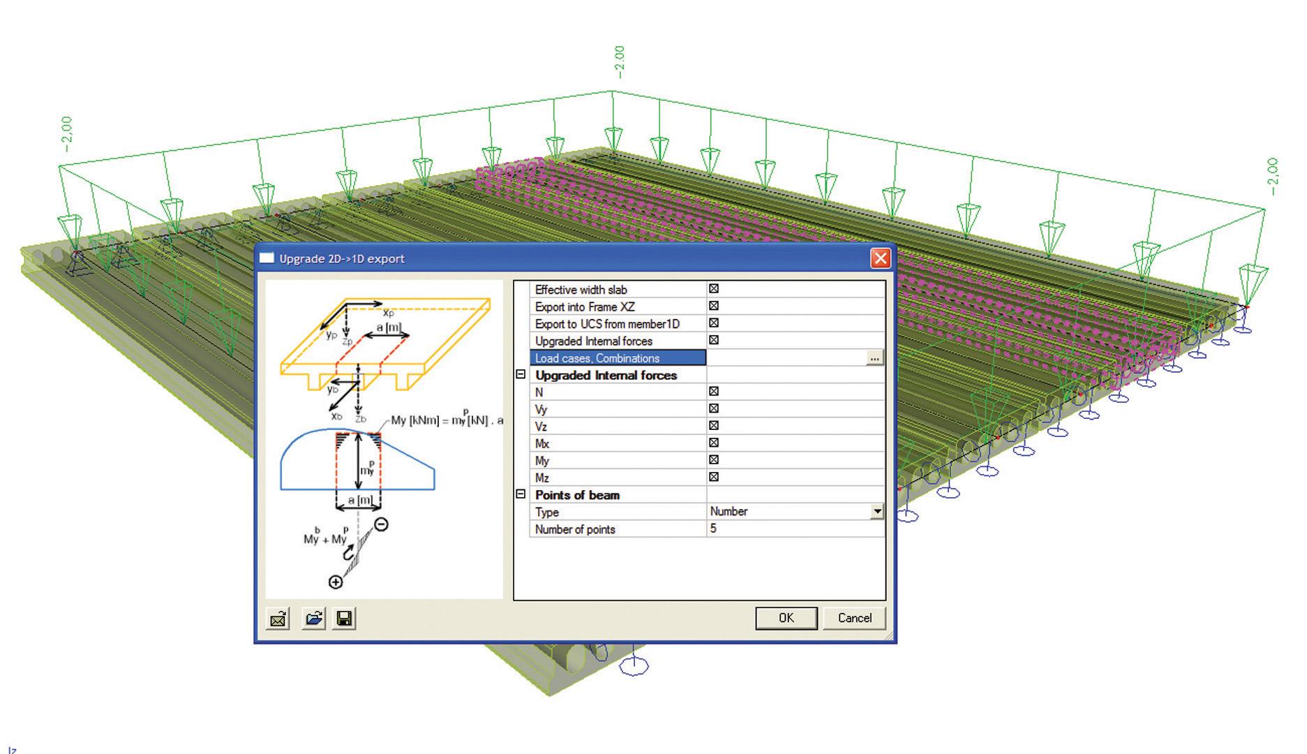
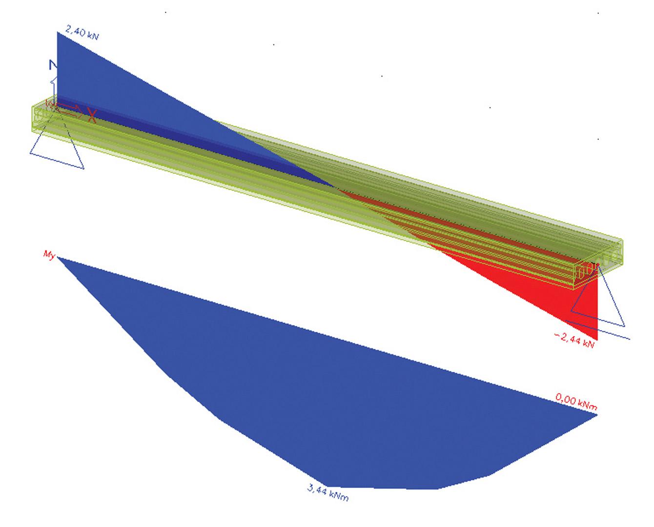
- It allows the user to select one or several beams from a ribbed slab and export these to a separate project into which load cases, combinations, and calculated internal forces from the original model will be transferred;
- The detailed check per beam (or panel) is performed in this separate project;
- The user controls the export through a set of parameters - effective width of the slab, coordinate system settings, options for loads and load combinations;
- The functionality is useful for the analysis of plates made of hollow core slabs or other prefabricated elements;
- The analysis of the whole structure in the original project (ESA file) is performed with a “substitute” plate, whose properties are equivalent to the ones of the beam/panel system.
Adaptive mesh
A fine mesh of finite elements produces more accurate results than a coarse mesh. Finding the optimal mesh size manually and selecting all needed parameters (e.g. the ratio element sides, the ratio of adjacent elements for mesh refinement) is sometimes a hard task.
Therefore, SCIA Engineer offers a method for automatic mesh refinement. The solution reflects the state-of-the art in a-posteriori error estimation methods. The method allows also for evaluation and display the the quality of results, derived from the geometry of 2D mesh elements.
Singularity check
Singularity check allows the user to control whether the model is unstable and/or is missing some translations or rotations. Members that are not connected are also detected, as well as problems with cross-links. Singularity check is performed after an unsuccessful calculation. The user can interactively inspect the resulting movement of the structure or its parts in the 3D window.
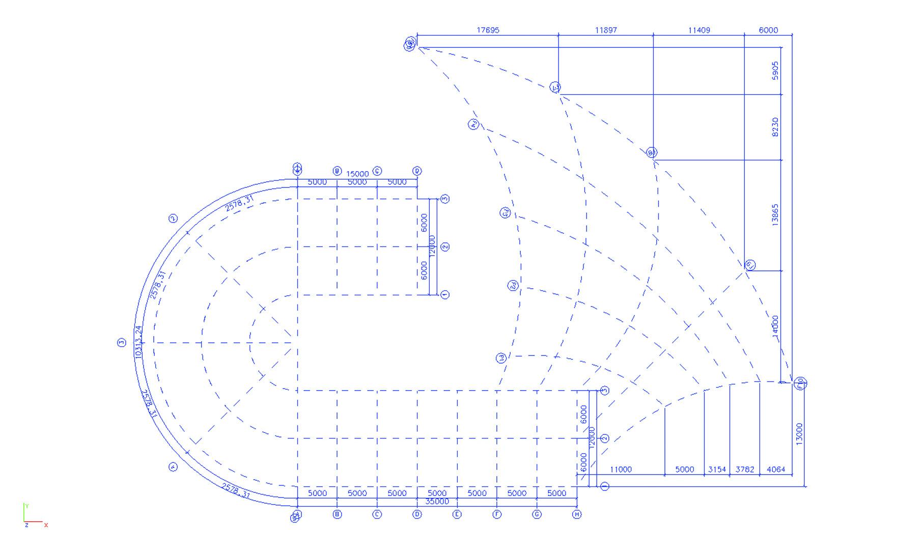
Advanced 2D/3D grids
Advanced grids and storeys ease modelling of complex structures, as well as creation of enhanced-quality drawings and calculation reports. Points, lines and shapes can quickly be defined in a 2D or 3D environment, thanks to the extensive grid functionalities:
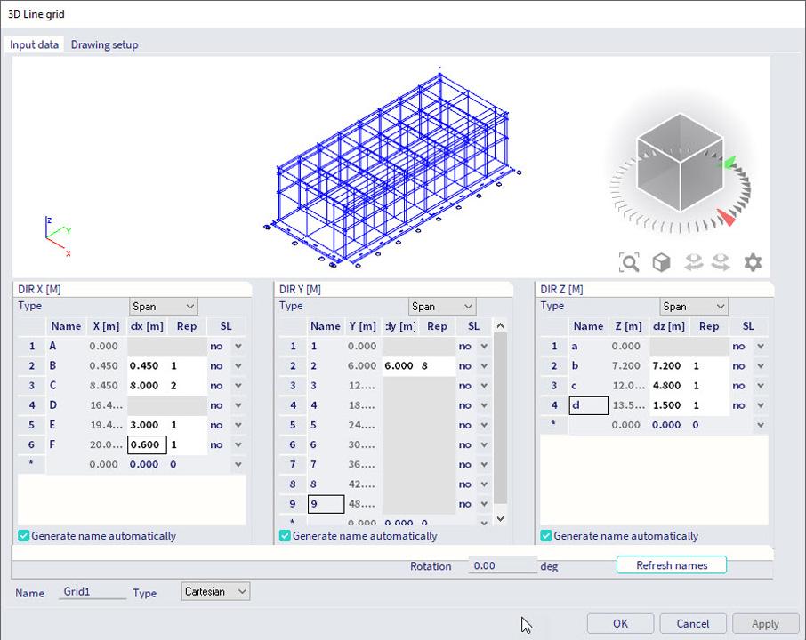
- 3D grids are defined by distance and angle increments; Cartesian, oblique, cylindrical and spherical grids can be created.
- Free lines are manually created grid-entities - SCIA Engineer recognises such straight or curved lines and adds them to the grid in the working plane. Free lines are useful when the model geometry is more elaborated, and the structure or loads are hard to define via Cartesian or polar grids. Coordinates, existing nodes or gridline intersections can be used to set up the free lines.
- Rectangular 2D grids are specified through X and Y increments and other properties (repetitions, origin, labels, symmetry indicator, etc.);
- Circular 2D grids are specified by X and angle increments and other properties;
- 2D grids can be composed of multiple grids of any type;
- In order to quickly create a complex random grid, rectangular or circular grids can be exploded into free lines, and then modified using the CAD functions of SCIA Engineer;
- Line grids are standard objects and modified using the corresponding property dialogues when selected.
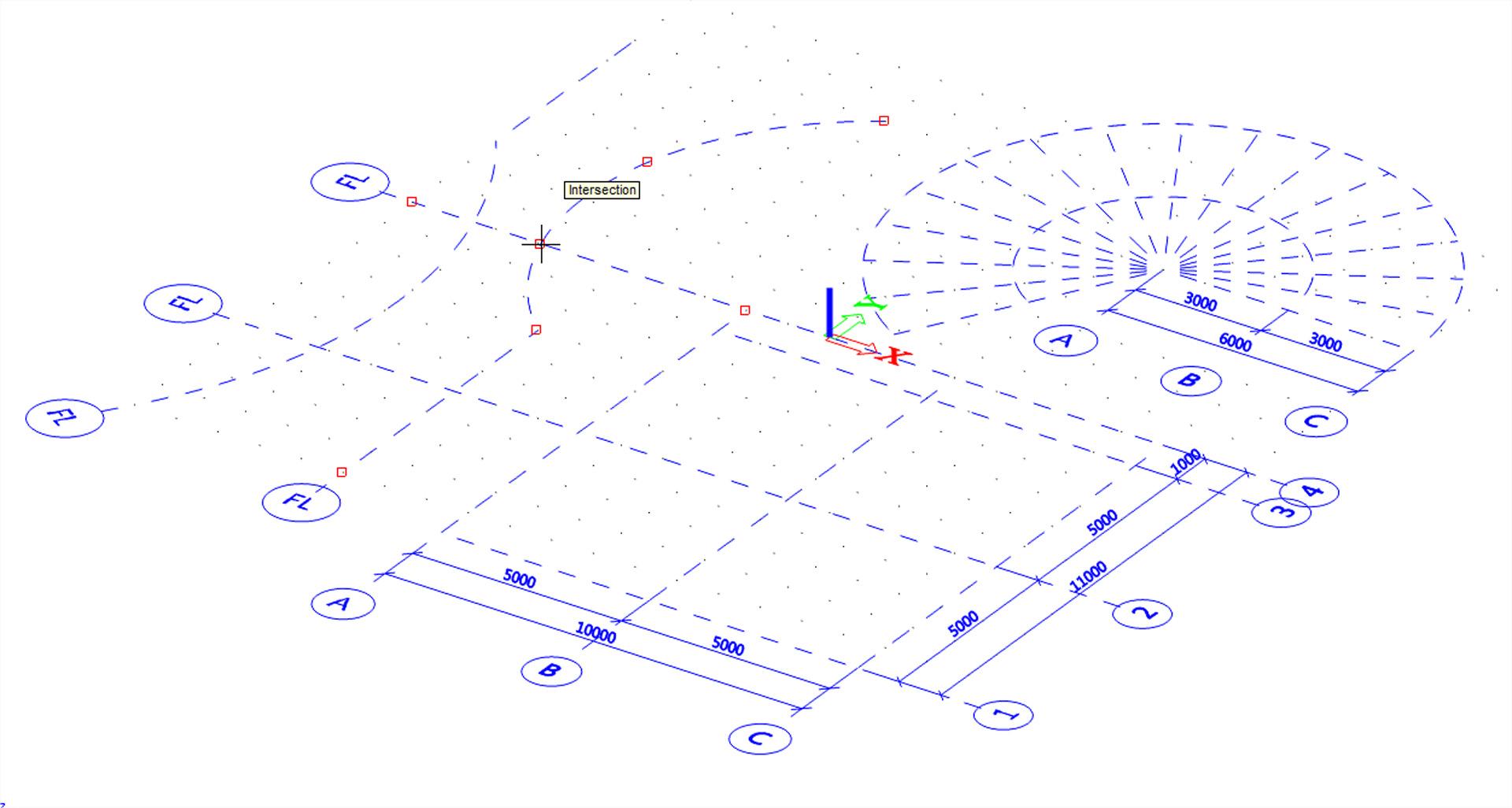
For free lines in 3D grids, see the paragraph "Storeys".
Climatic loads
Wind and snow loads are generated on the structure based on user-defined wind and snow pressure curves.
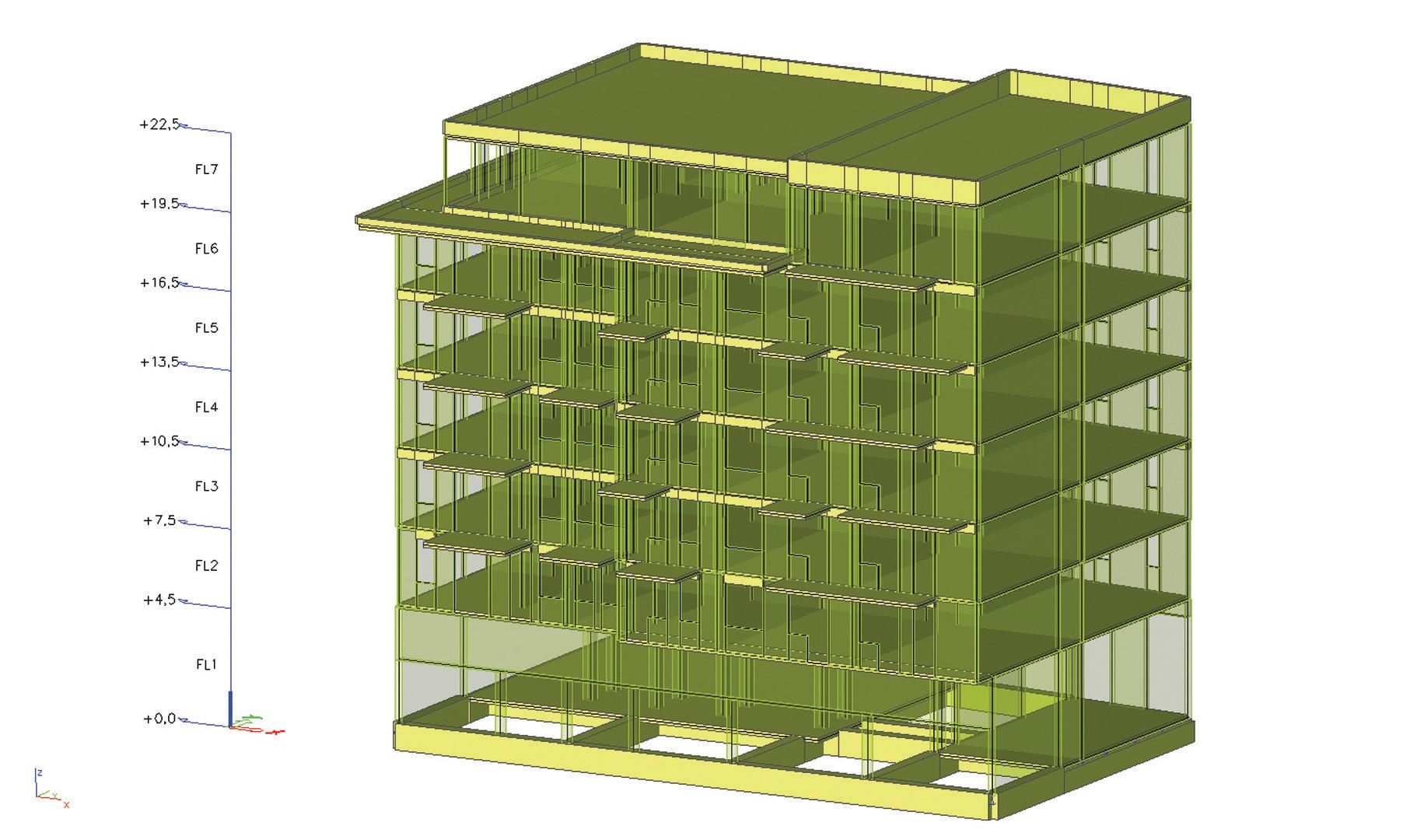
Storeys
A storey assembles together entities located at the same elevation in a model.
- Storeys are indicated in the 3D window of SCIA Engineer by means of inbuilt dimension lines;
- A 2D grid is projected easily onto every storey, allowing for the definition of custom, free-line 3D grids;
- Storeys allow for analysis being made per floor level, which is often required for seismic and stability analysis;
- Seismic-related summary and detailed results are printed per storey.
Design Groups
Design Groups is a concept that allows the engineer to easily manage design and checks of members that share certain properties, such as member type, length or cross-section. This concept simplifies the design process as it shifts the focus from a single member to a whole group of similar members. The design of all members in one design group is performed in one step for the envelope of result values obtained from all members in the group.
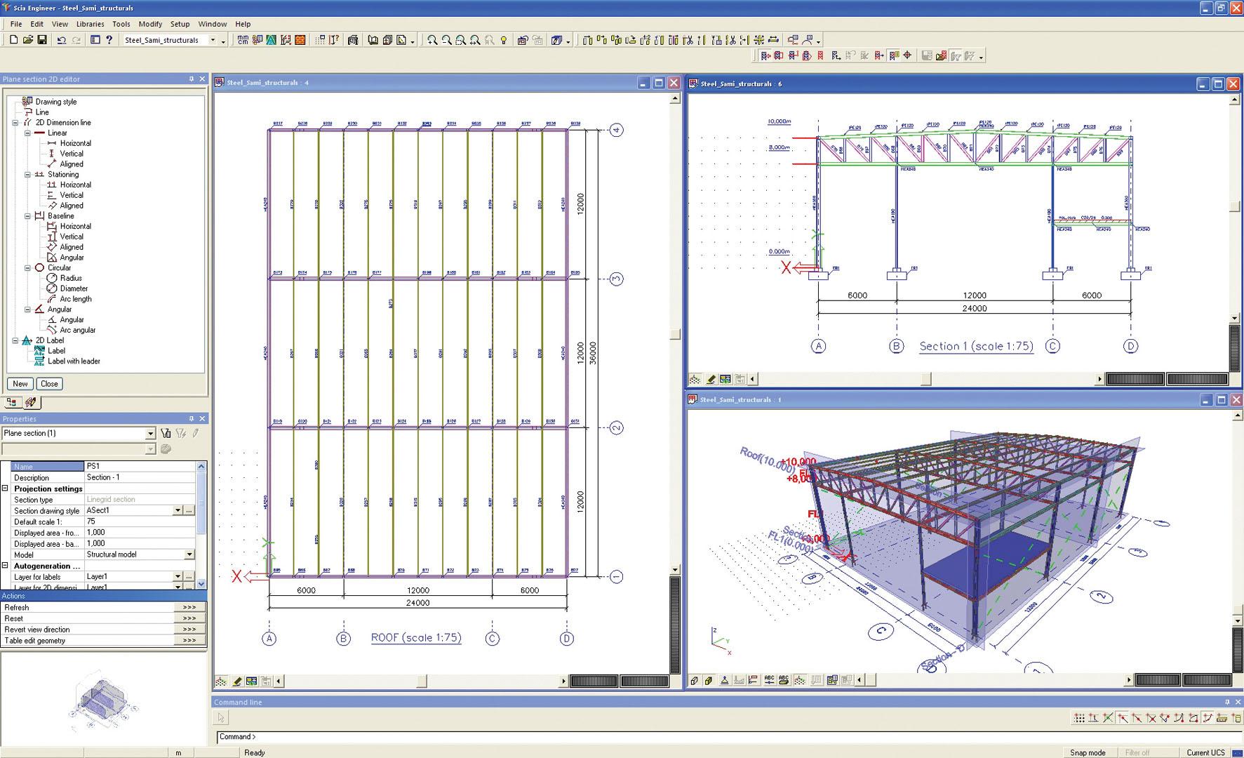
Sections
Plane Sections create 2D views of a 3D model. 2D plane views are created using clipping boxes, whose boundaries can be adjusted to limit the display to relevant parts of the structure.
- The user defines vertical, horizontal and skewed (general) plane sections;
- The view is always perpendicular to the section plane and each plane section has a fixed working plane;
- Modelling errors can be corrected, in cases when 3D views are misleading;
- All editing functions accessible from the 3D window are also available in 2D views;
- Plane sections are defined when automated General Arrangement drawings need to be created.
3D Dimension lines
Dimension lines are defined in both 2D and 3D views in SCIA Engineer.
- Supported dimension types include - offset dimensions, also aligned, radial, diametrical, angular, etc.;
- Dimensions are managed via the Dimension Styles Editor and via the properties per dimension line;
- Settings are available for labels, label positions, line types, end marks, etc.;
- Layers for dimensions are supported;
- Snaps to 2D/3D grids and objects simplify the definition of dimension lines.
External MS Excel checks
Users sometimes need to perform custom checks on available analysis data. User-defined checks in spreadsheets can be integrated and used within SCIA Engineer.
- The External Application Checks functionality allows the user to define his/her own calculation algorithm by linking one or more Excel files;
- The link is bi-directional - data from SCIA Engineer (internal forces, member data, loads, dimensions, etc.) are sent to Excel and results are read back;
- Results are displayed in a similar way as for internally calculated results - as diagrams along beams, numerically in the Preview window and in the Engineering Report;
- Selected regions from the spreadsheet can be shown in the calculation report as static images.
Picture and drawing galleries
The Image and PaperSpace galleries are advanced tools for the preparation of images. These allow for the production of sophisticated graphical documentation in reports and sneak previews.
- Images are created using the right-click contextual menu in the SCIA Engineer 3D window and are stored in the Image Gallery.
- The images remain dynamically linked to the model, which means these are automatically updated after changes are made in the structure or load definition. The user does not need to redefine images after making changes in the model.
- Previously defined automated text, dimensions, etc. are also adapted.
- The images retain information about how they were created and which part of the analysed structure they display. This makes it simple to change the images using the Properties Window - by adapting viewpoints, load cases or combinations, displayed entity, etc.
- If required, the pictures may further be edited in a built-in graphical editor where standard graphical functions are available, such as Draw Line, Add Dimension Line, Add Text, Move Object, Copy Object, etc.
- The images may be exported in the most common picture formats - BMP, WMP, VRML, U3D, EMF, EP3, DWG and DXF.
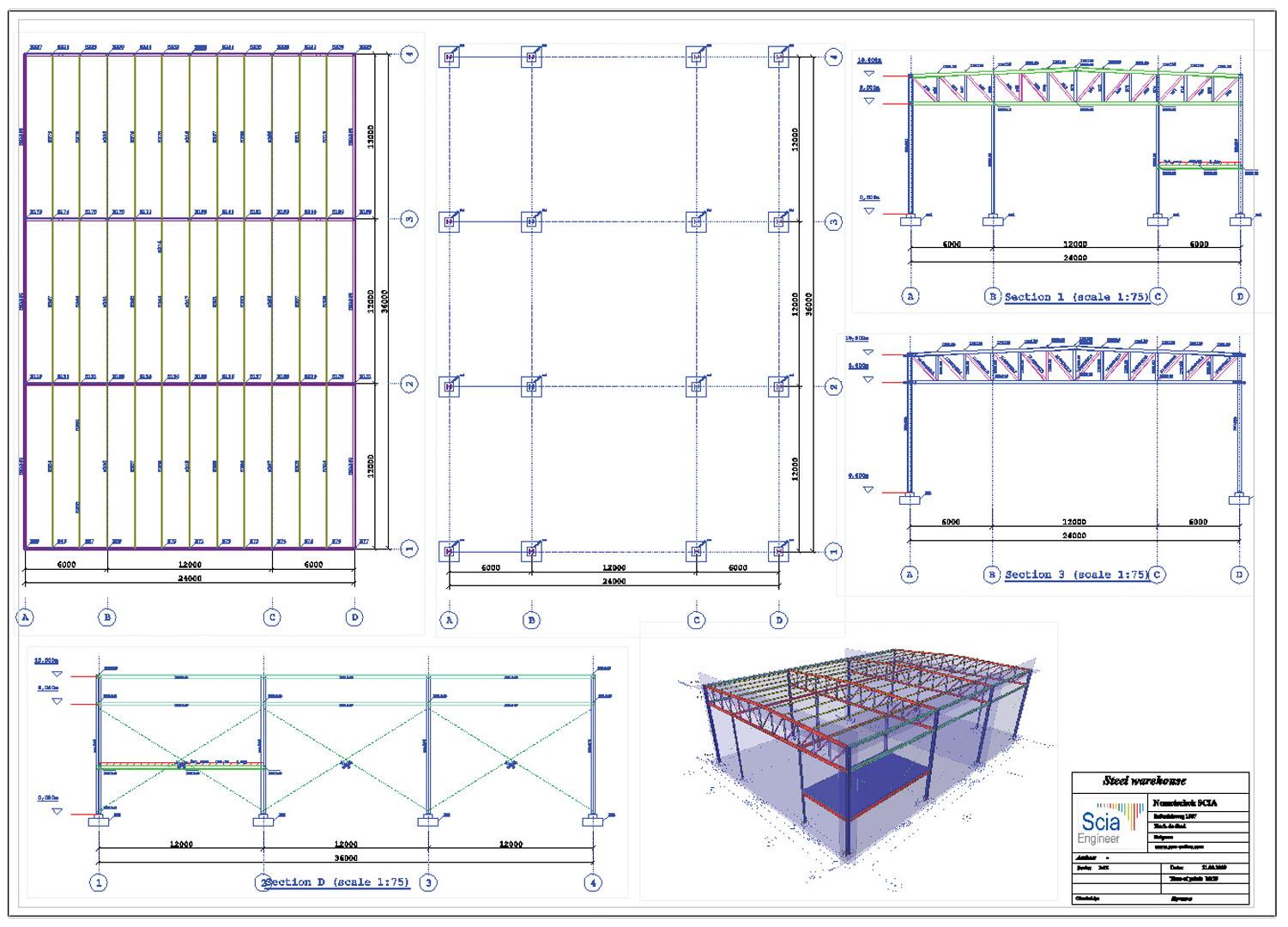
General arrangement drawings
SCIA Engineer is equipped with tools for fast preparation of general arrangement drawings. SCIA Engineer automatically generates plan views, vertical or arbitrary section views. The drawings are then generated from these plan views and sections. The drawings are made according to user-defined rules, which makes it easy to keep e.g. a unified company style, etc. The generated drawings can be further processed, and e.g. basic dimensions lines or adjustable labels can be added.
The generated drawings can be edited in the integrated editor. You can then add other elements such as dimension lines, labels, leads and other graphical entities (solids, surfaces, lines, curves, texts) manually. The final drawing containing frames, title blocks, etc. is composed of several partial drawings and is stored in the PaperSpace Gallery.
Integrated regeneration tools update the generated drawings so that they reflect the state of the structure after any changes made to the model while keeping the manually added entities (dimension lines, labels etc.) untouched.
PDF export from Gallery
Export of report documentation to PDF is supported.
- 3D Graphics are included in 3D PDFs, where these can be zoomed, panned and rotated from within Acrobat Reader and other free readers for *.pdf files;
- Images are saved to PDF directly from the Image Gallery.
Engineering report
Engineering report is state-of-the-art tool for creating and managing structural documentation entirely in the environment of SCIA Engineer. Engineering Report allows the user to add contents of any library, geometry, loads, results and checks presented in customizable form either graphically, or in a tabular view. Styles for chapters may be defined, header and footer may be defined as well. Chapters are automatically numbered; Table of contents is available and automatically updated based on the content of the report.
Advanced possibility of indenting images under libraries (materials, layers, cross-sections, etc.) lead to automatic generation of images both with the structure and results. If images are created this way, changing single reference image leads to update of series of images that are automatically generated. This option provides efficient way of creating extensive reports of structures with high number of members.
Besides the possibility of showing internal data form the structural model in SCIA Engineer, Engineering Report may show external data, such as:
- External images and DWG/DXFG drawings, with customizable styles of lines. Images may be inserted directly by copying and pasting them in the Engineering report, or they may be referenced to an image file on user’s hard drive.
- External text file or a table from MS Excel. Separate sheets may be displayed with multiple options. Engineering report may show either whole content of the sheet or for example only printable area of the sheet or custom selection of cells.
- Link to external PDFs or reports may be established.
- External items may be either embedded or linked to source files on users’ hard drive, in this case the content may be regenerated, if the reference files are changed.
Engineering report allows multiple type of export formats:
- Export to MS Word (.rtf) or MS Excel
- Export to PDF or HTML
- Export as report for special workflows in the case of extensive structural reports.
Exports may be done manually or automatically. Automatic regeneration and export after FE analysis is also possible.
Design Forms in Engineering Report
Design Forms is a standalone scripting tool that complements SCIA Engineer and allows users to write their own design checks using analysis results from SCIA Engineer. Short, dedicated calculations can be executed via Design Forms providing transparent output. The Engineering Report features an item in the “Special Items” group, which allows the user to insert the output report of a Design Forms directly into the Engineering Report.
Engineering Report templates
In the Engineering Report, predefined templates are provided with installation, while users can also create their own report templates. A full document (content + layout) or only a ‘snippet’ (block of Engineering Report items) may be composed and stored for use with new projects. A document can be composed of several templates, optionally accompanied by ad-hoc added user-defined content.
HTLM export from Engineering Report
The HTLM export in the Engineering Report of SCIA Engineer offers some additional features:
- (Export to Excel via HTML) Exported HTML files are opened and edited in Excel, where all tables are configured with headers and units, and all images are added as BMP/JPG/PNG or GIF files;
- (Export to Word via HTML) HTML files are opened and edited in MS word, where a similar layout to the one shown in the Engineering Report is used.
Attributes
An attribute contains additional data about a modelled entity - extra properties (or tags, or descriptions) can be linked to any structural member (beam, column, slab, brace, etc.).
- An attribute contains strings, numbers, checkboxes and combo-boxes.
- The user defines a list of valid data for each defined attribute (e.g. a list, a range of values, etc.).
- SCIA Engineer does not differentiate between hard-coded properties and user-added attributes when reporting, making images or drawings, or during exchange of data through standard interfaces such as XML.
- Numerical attributes are defined as "summable" properties, whose sum can be listed in the Bill of Material.
- Attributes can be used when performing external checks in Excel.
- Use of user-defined attributes minimises losses during the BIM process.
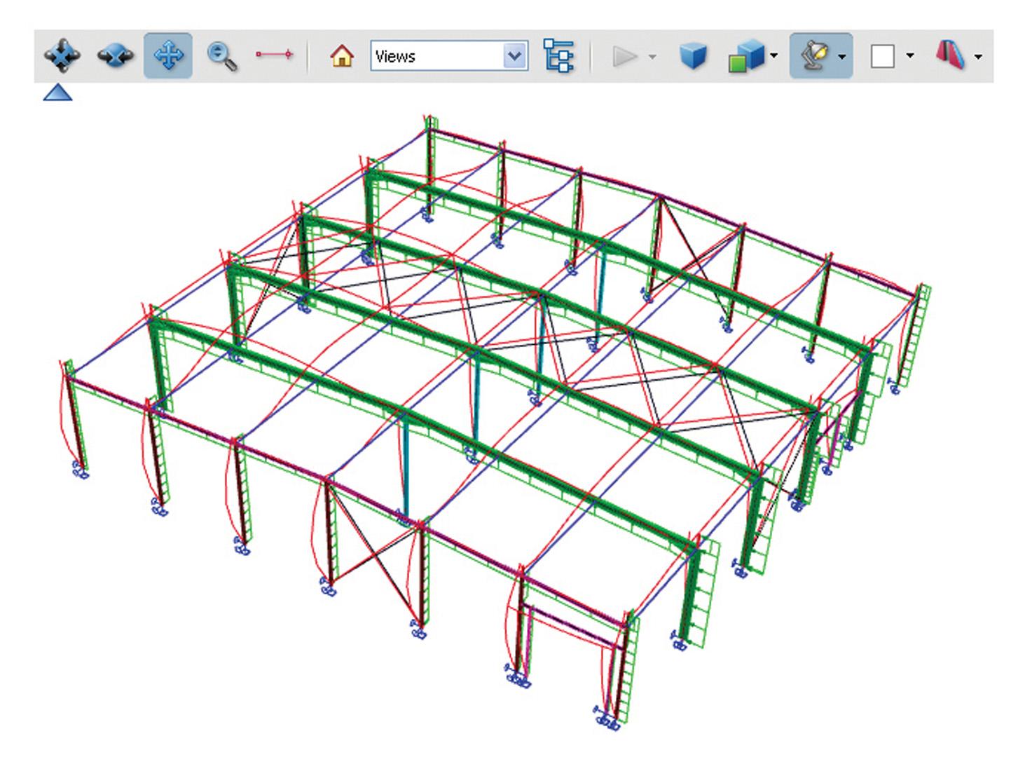
Bridge design EC
Bridge design requires specific calculation rules. A bridge is subjected to specific types of loads like traffic loads, footfall load, conduits used for the movement of goods and materials, and so on.
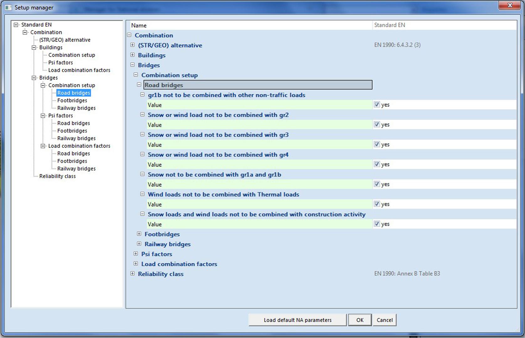
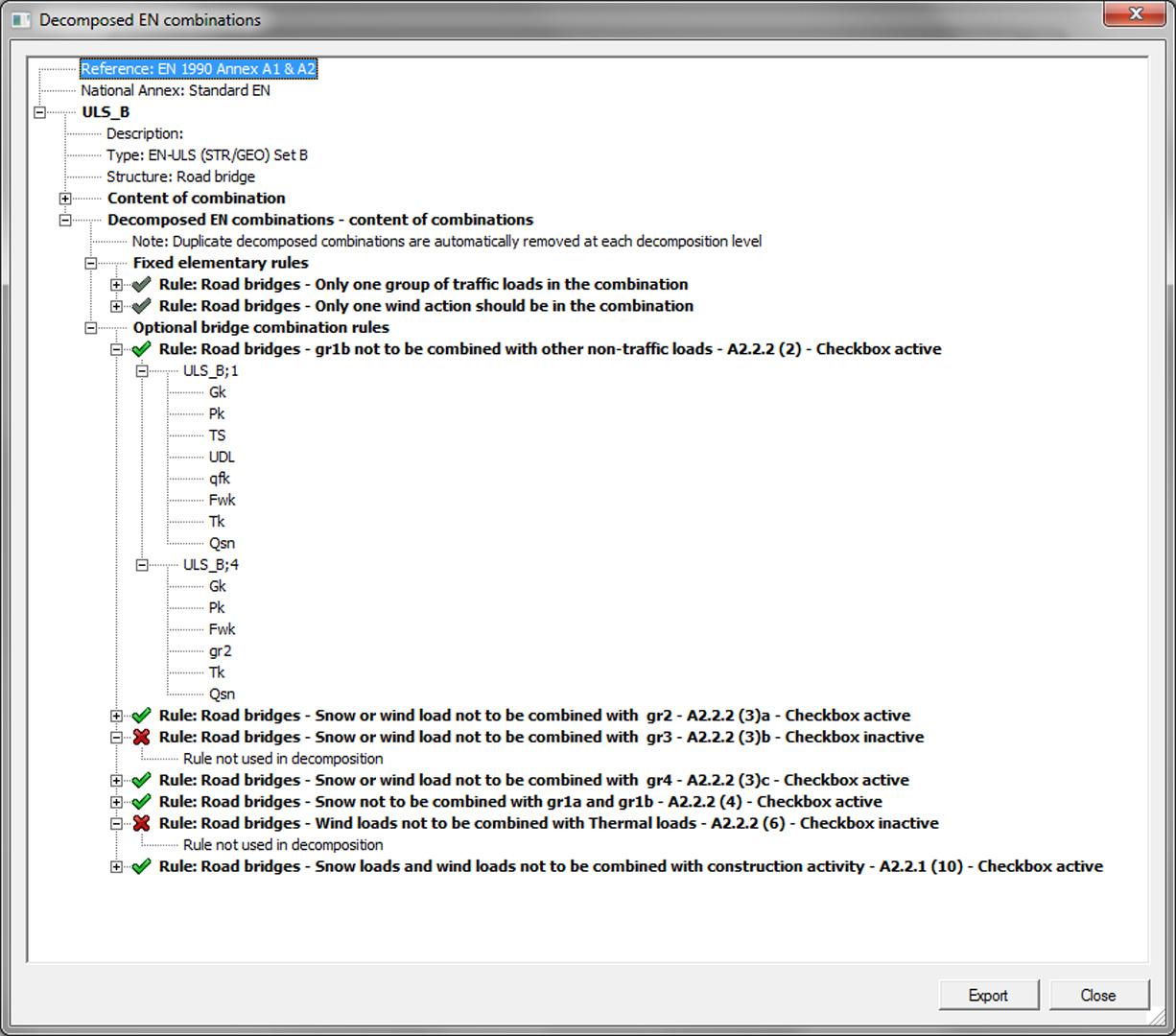
The module allows the user to define bridge combinations according to Eurocode 0 for 3 types of bridges:
- Road bridges,
- Footbridges and
- Railway bridges.
Advantages
- To prevent mistakes during the input of the combination, a filter has been added which helps the user to create either a combination for buildings or for bridges.
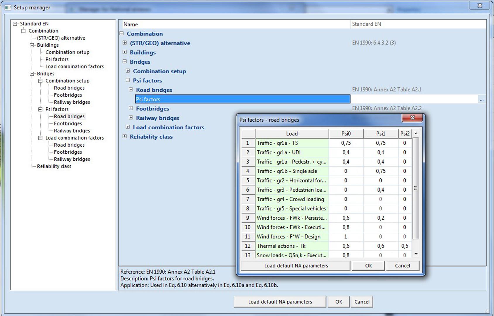
- Bridge combinations are rather complex due to the big range of Psi factors (safety factors) and the numerous combination rules for the specific types of loads. To make this more transparent for the user, a dialogue shows the decomposed EN combinations.
- Bridge combinations are automatically generated according to rules and factors as prescribed by Eurocode 0.
- Predefined load groups for each bridge type are available.

Want to try SCIA Engineer yourself?
Explore how our software and services can help you optimise your work and boost your productivity. Try it for yourself with a free 30-day software trial.
Download a free 30-days full trial