Highlights
- Fast and simple generation of general arrangement drawings in user-defined section.
- Automatic generation of detailed connection drawings.
- User-friendly management of generated drawings and pictures.
- Export of drawings to CAD programmes.
SCIA Engineer is equipped with tools for fast preparation of general arrangement drawings. SCIA Engineer automatically generates plan views, vertical or arbitrary section views. The drawings are then generated from these plan views and sections. The drawings are made according to user-defined rules, which makes it easy to keep e.g. a unified company style, etc. The generated drawings can be further processed, and e.g. basic dimensions lines or adjustable labels can be added.
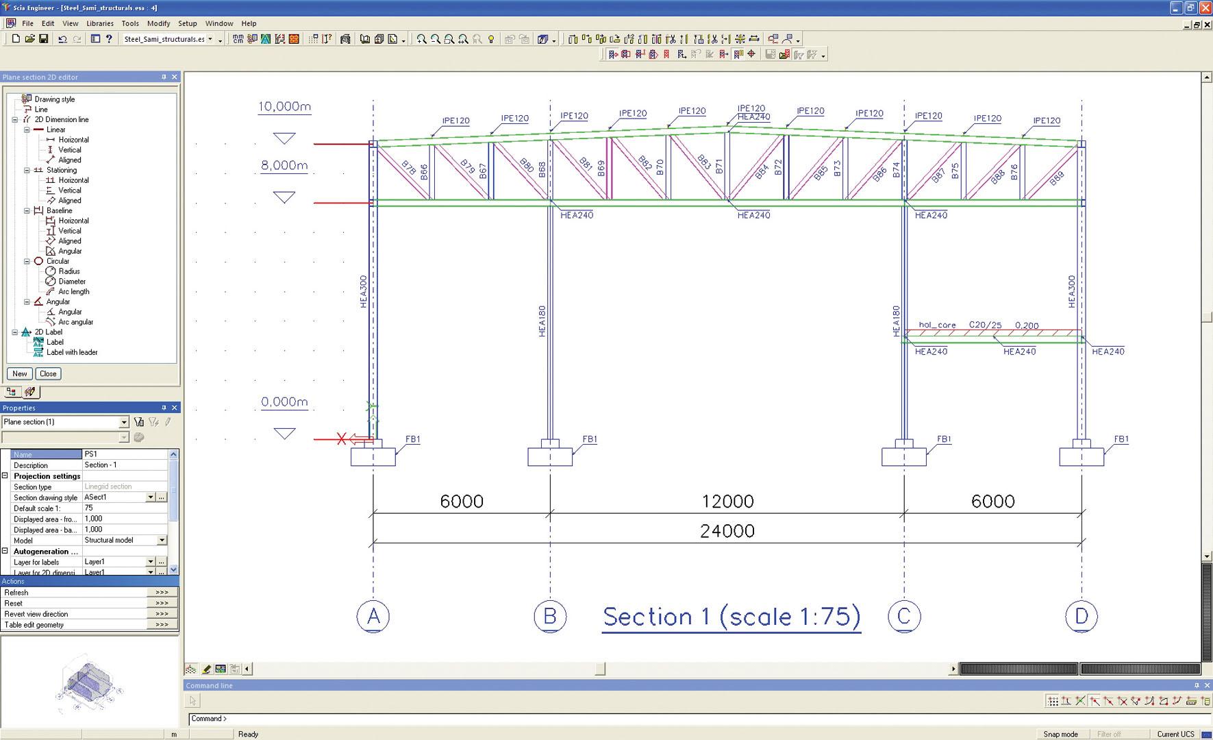
The generated drawings can be edited in the integrated editor. You can then add other elements such as dimension lines, labels, leads and other graphical entities (solids, surfaces, lines, curves, texts) manually. The final drawing containing frames, title blocks, etc. is composed of several partial drawings and is stored in the PaperSpace Gallery.
Integrated regeneration tools update the generated drawings so that they reflect the state of the structure after any changes made to the model while keeping the manually added entities (dimension lines, labels etc.) untouched.
Shape of the structure
SCIA Engineer keeps two shapes (models) of each member: analysis model and structural model. The former is necessary for accurate calculations, the latter for quality drawings.
Preparing the drawings is rather easy thanks to, among others, the ‘CAD type’ member parameter that defines the member priority in the joint connecting the member to the rest of the structure. Other CAD properties of each member (eccentricities, longitudinal offsets, end-cutting toggle etc.) enable you to generate the precise shape to be displayed in the drawings.
The General Arrangement Drawings functionality offers even more. Member-offsets can be applied to the drawing only. There is no need to manipulate the analysis model in order to get the drawing right.
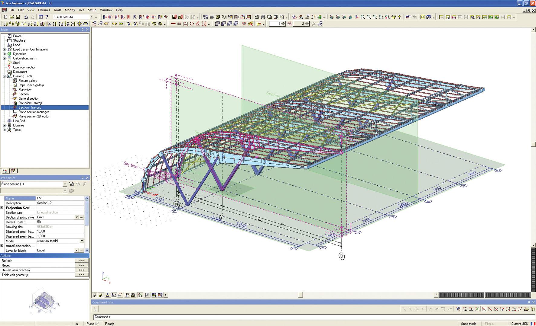
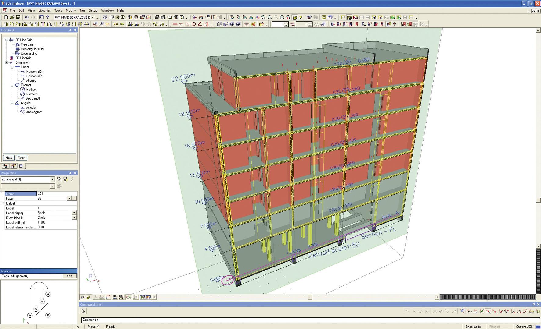
2D and 3D-Linegrids - general tools for the definition of sections
The 2D and 3D line grids are not only tools for graphic input of the structure. They also help you with the production of the drawings.
Storeys - general tool for the definition of plan views
Similarly to the creation of sections by means of line grids, storeys can also be used to generate plan views. In combination with the 2D line grid functionality they stand for a powerful aid for the production of drawings. The storeys are also useful for modelling of the structure.
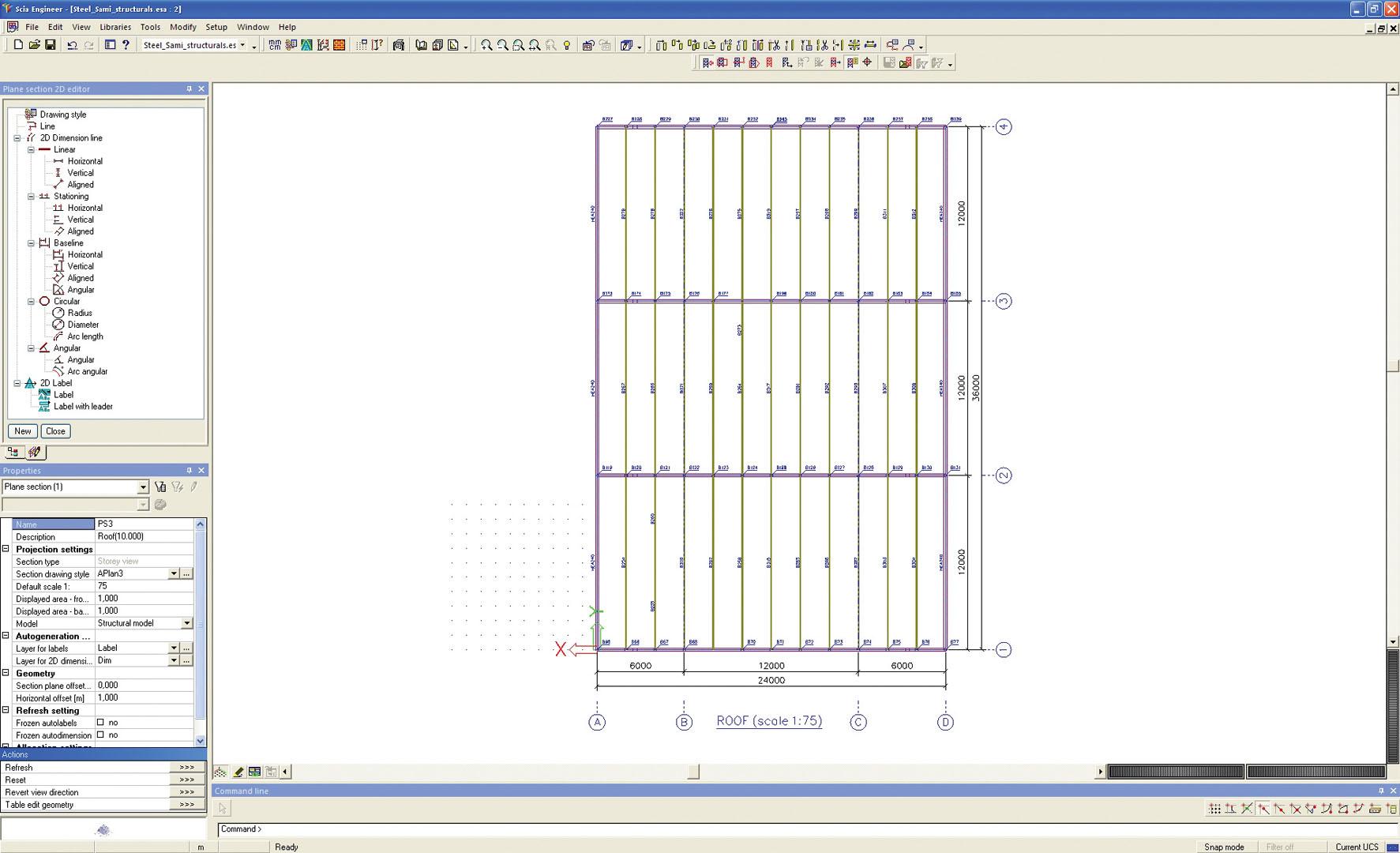
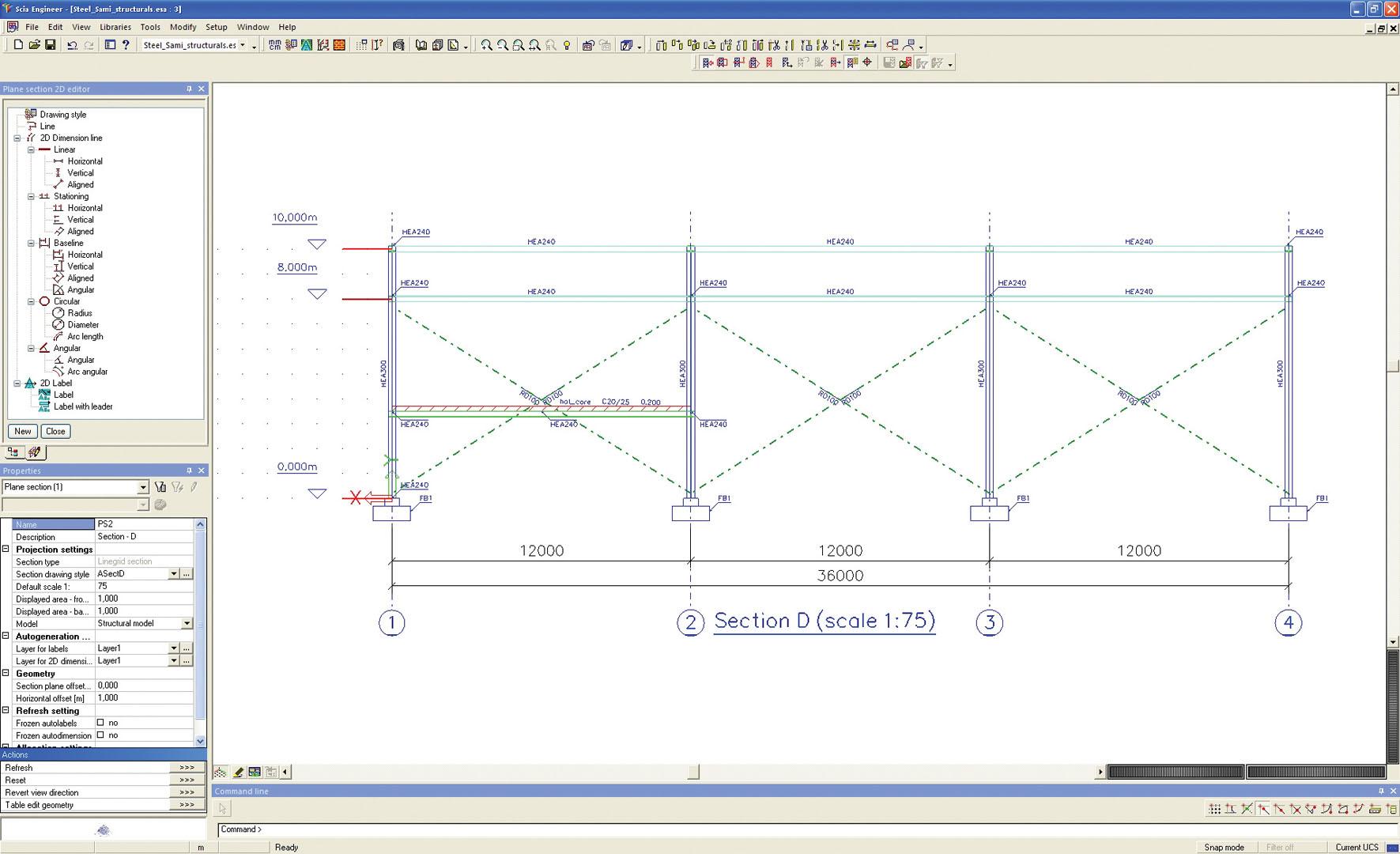
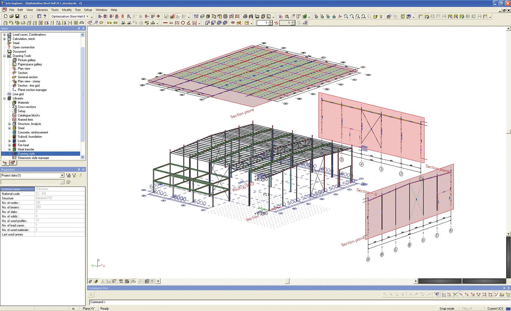
Sections
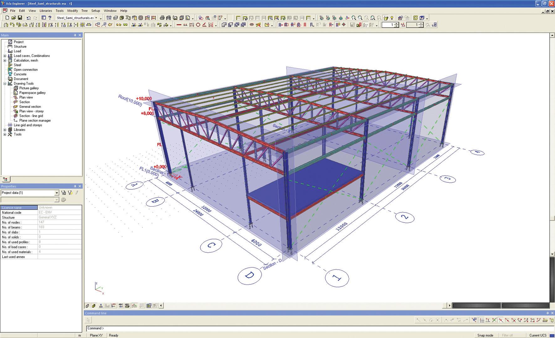
A section is a basic entity used for automatic generation of drawings. The section is defined by its geometry and rules that control the generation of the drawing (see section Drawing styles below). The plan view or section is created simply by clicking a number of points in the graphical window. And when using line grids and storeys life becomes even easier. The selection of individual planes, defined by line grids or storeys, directly generates plan views and sections. The applied drawing style then define the layout of the drawing.
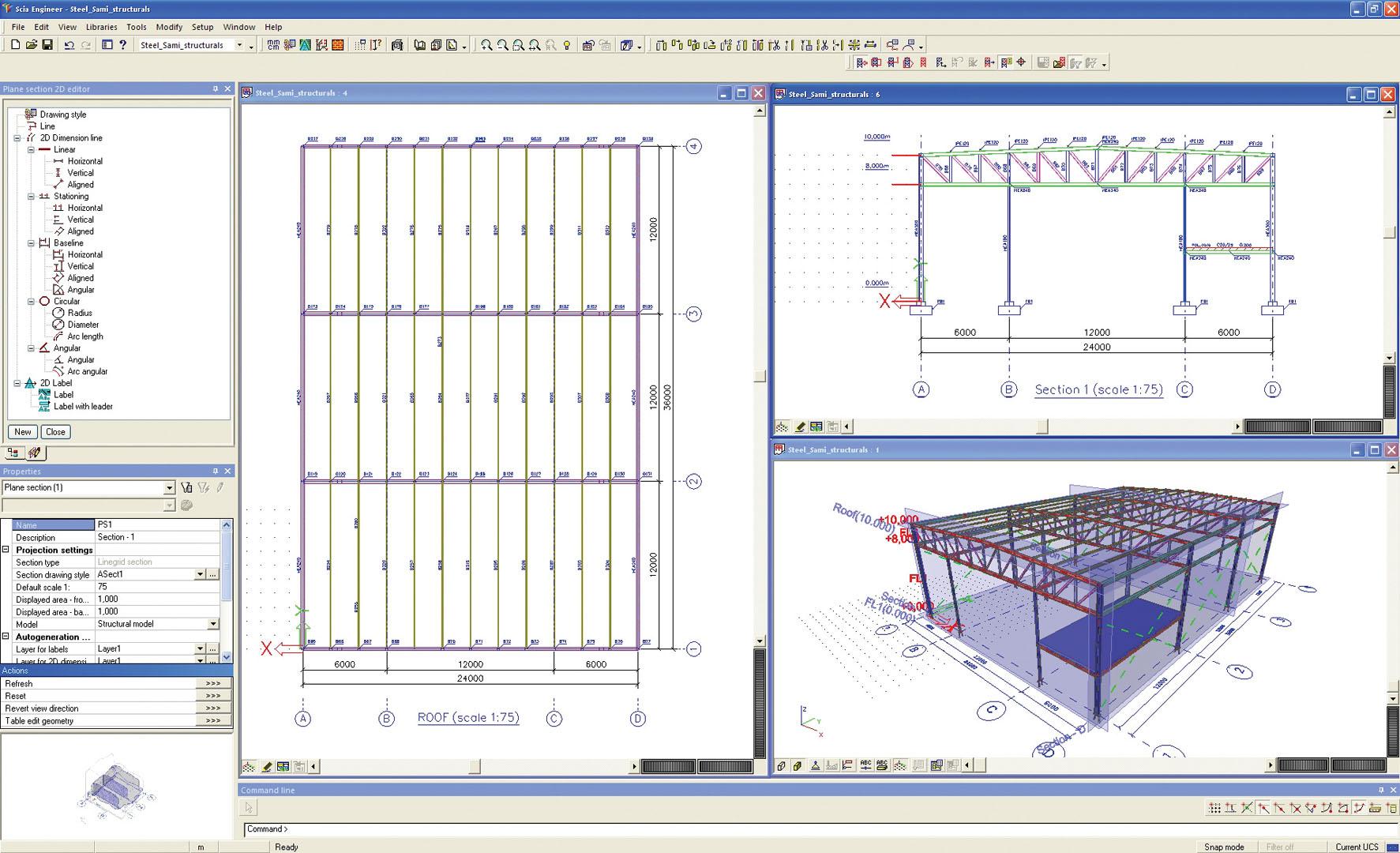
Plan views and sections can be selected in the 3D-model view and their parameters can be modified in the traditional property dialogue. The user can control the way in which they are displayed.
Each section has a section plane, a front plane and a back plane. Elements which are in between the front-plane and back-plane are drawn in the 2D drawing. The drawing rules define the style in which the parts of the entities located between the front- and back-plane are displayed.
Drawing styles
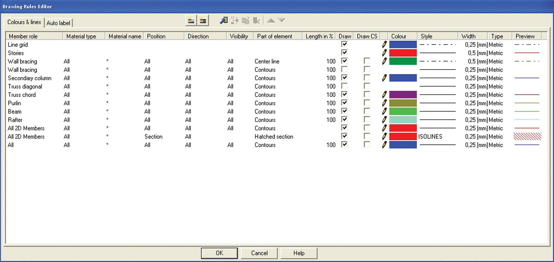
The heart of the GA drawings lies in the drawing styles and rules. The drawing rules determine how the model is transformed to a 2D representation. They consist of filters (object type, materials, …), format properties (line style, pen width, colour) and what-to-represent (centreline, contours, section).
Autolabeling and autodimensioning of openings, anchor bolts and purlins can be configured in the drawing styles as well.
The key-part of GA drawings are the four style managers:
- Drawing-style Manager
- Label-style Manager
- Dimension-style Manager for dimension lines
- Hatch-style Manager
Being managed by a standard SCIA Engineer database manager, the Drawing styles can be easily transferred to other projects and shared by several users.
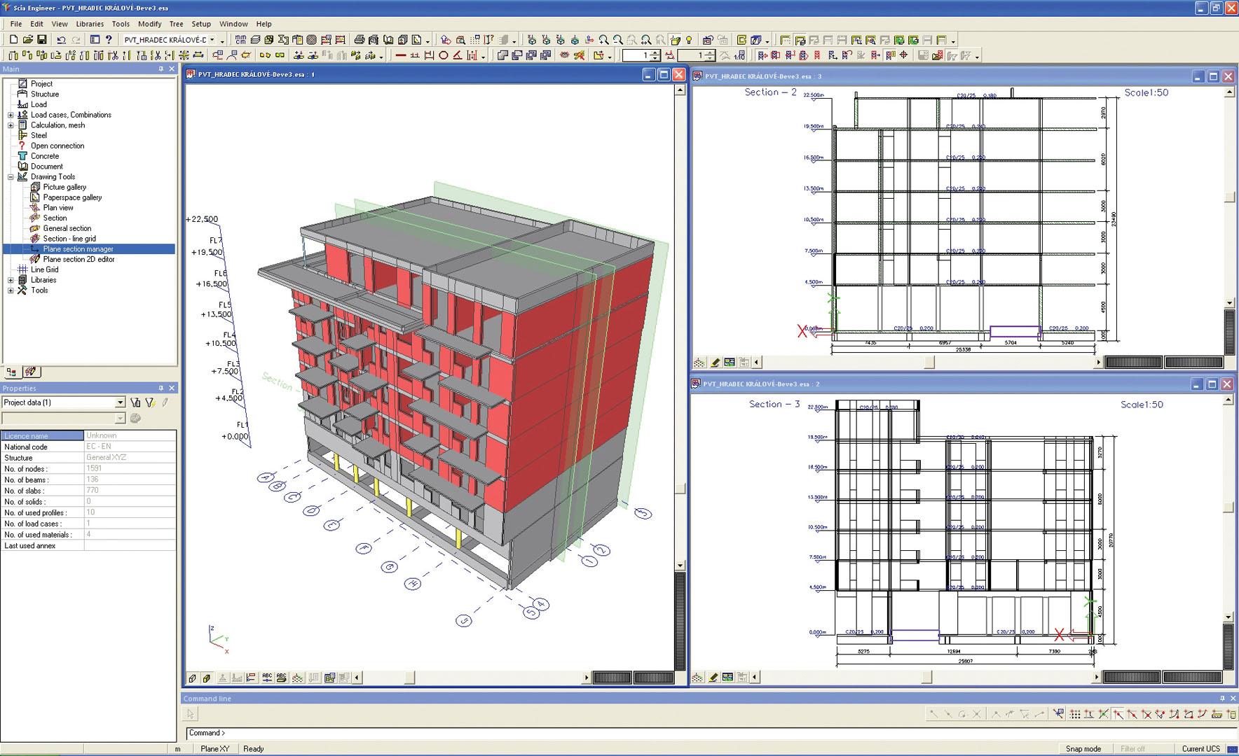
Drawing manager
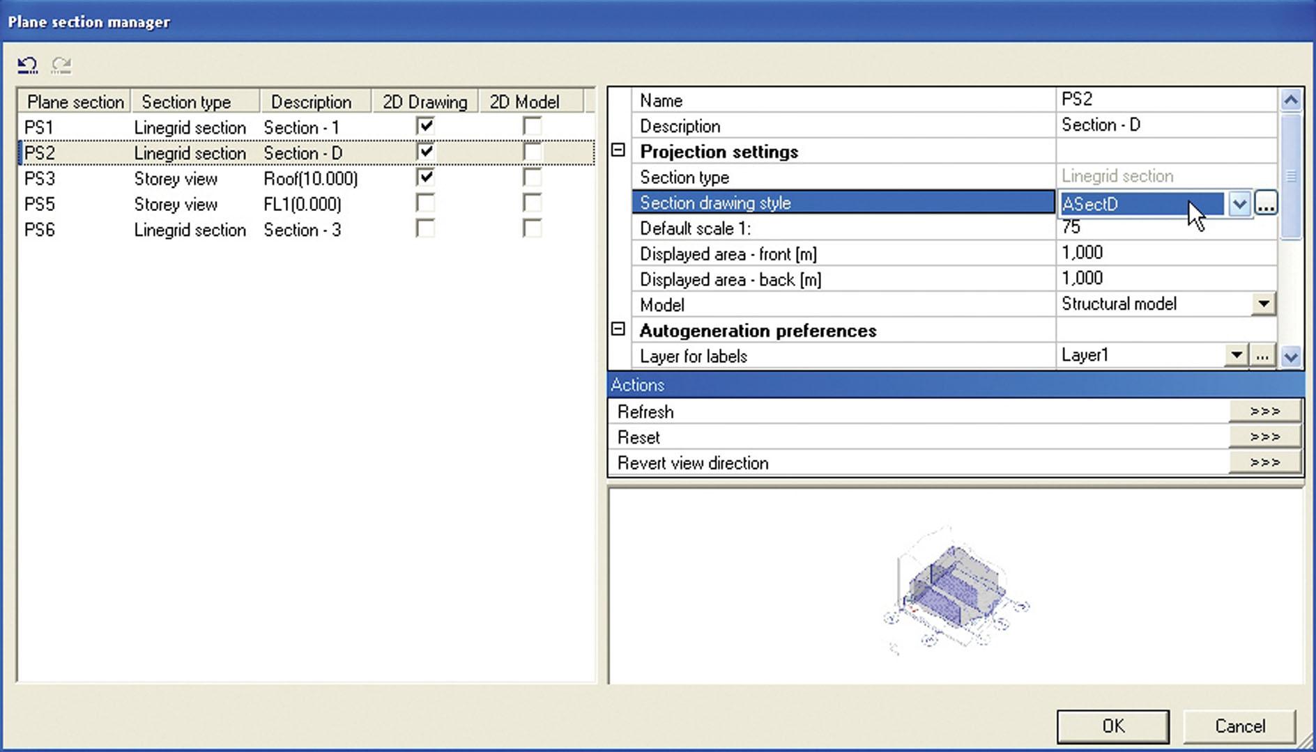
The Drawing manager manages all available sections and plan views. This utility has a dual purpose:
- Basic properties (scale, prefix of picture name, hidden lines options etc.) can be adjusted. Display variables (e.g. view direction, depth of section, horizontal and section plane offset, etc.) can be set
- Drawings can be opened in the 2D editor for customization: extra dimensions can be added, labels can be moved, etc.
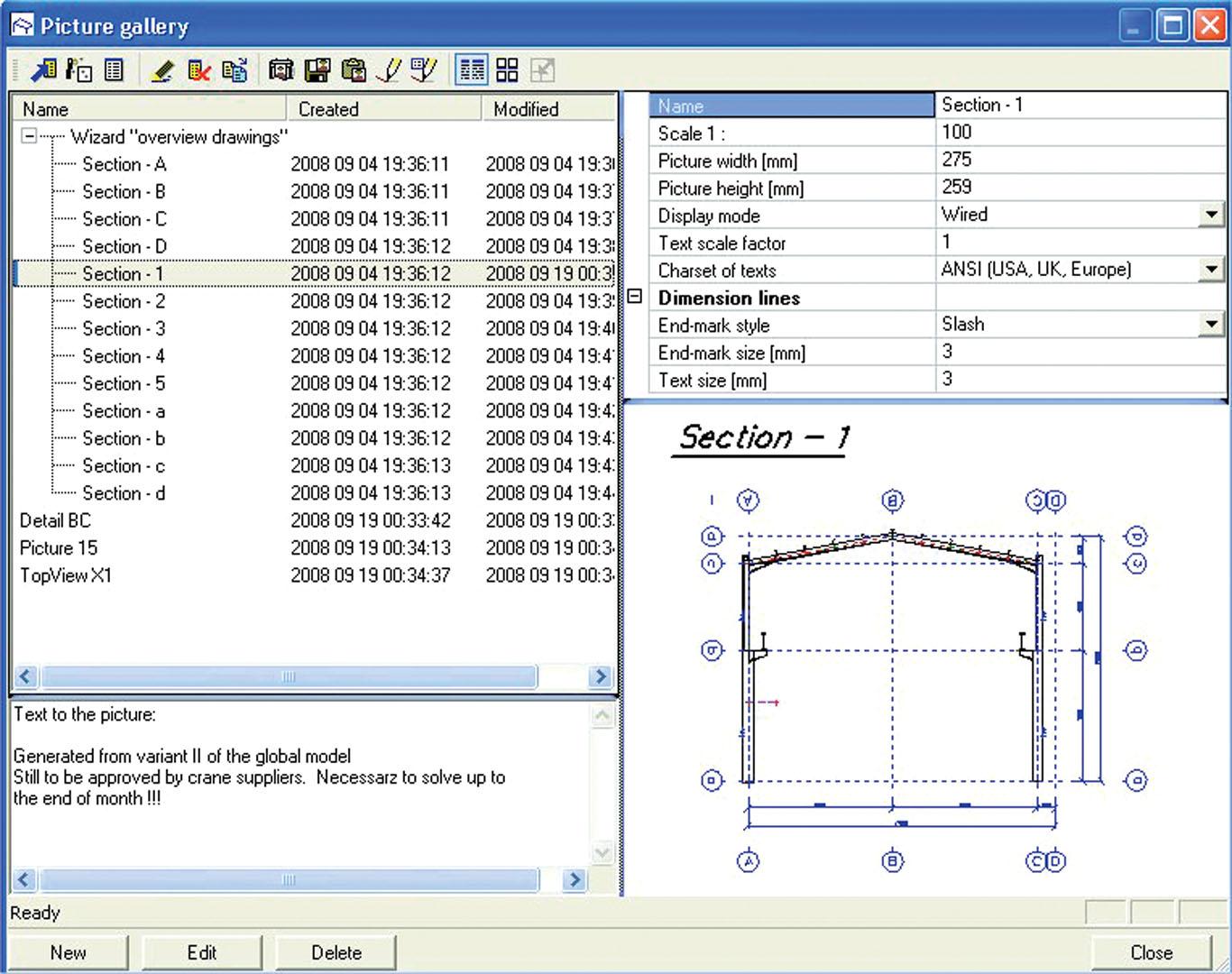
Picture Gallery - efficient handling of pictures
Pictures generated by program wizards or saved from the graphical window are sent to the library of pictures called Picture Gallery. You have an immediate preview of all pictures and you can edit their properties. Any picture can be modified in the internal graphical editor. You can add dimension lines, texts or standard graphical shapes, as well as edit line thickness, style and colour. The layer manager makes it possible to set selected parts of the picture as hidden or frozen. 3D clipping and picture border settings are available for adjusting a part of the structure to be displayed. The Gallery editor can also be used as an efficient drawing tool for preparation of 2D pictures or charts.
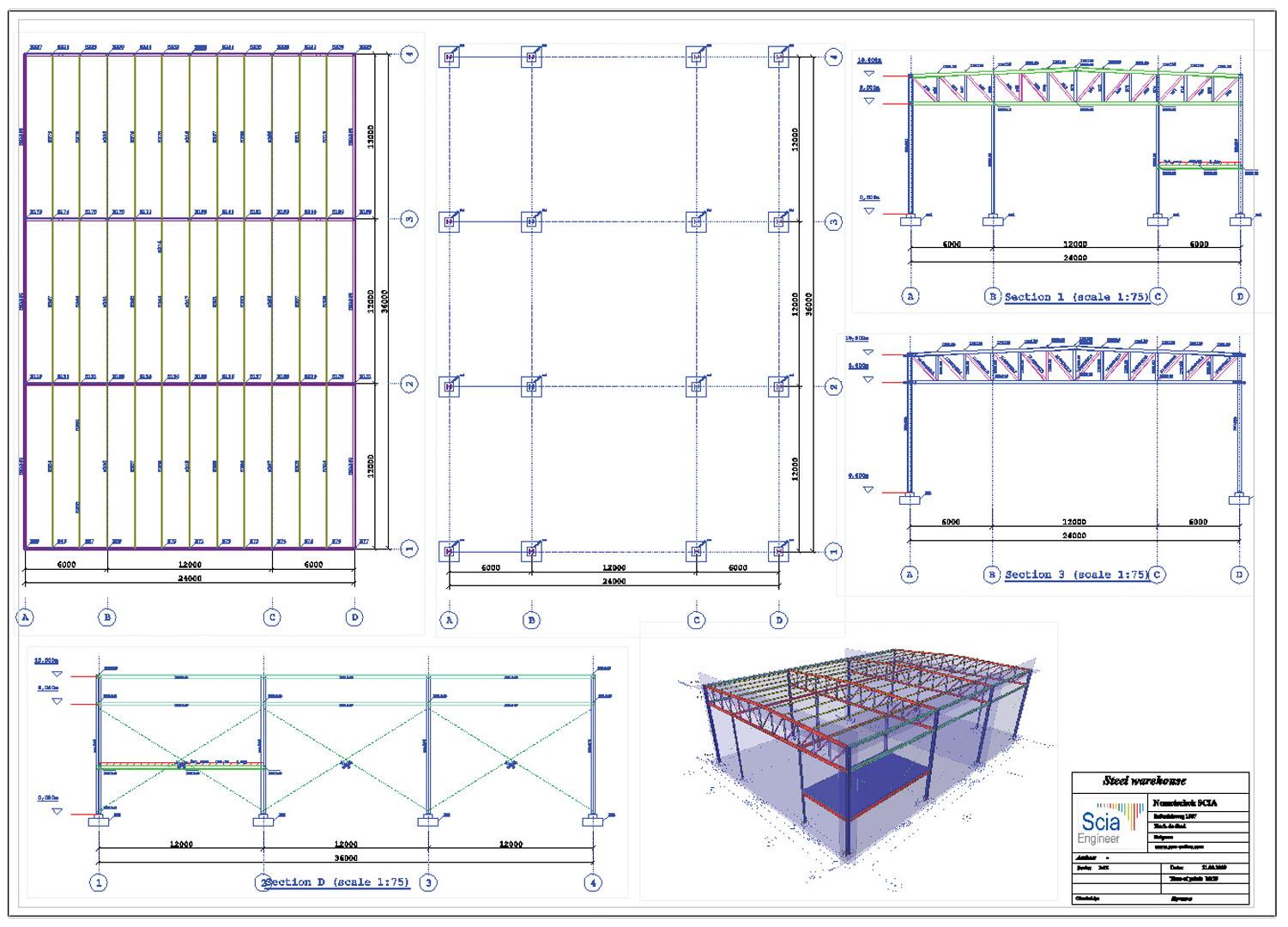
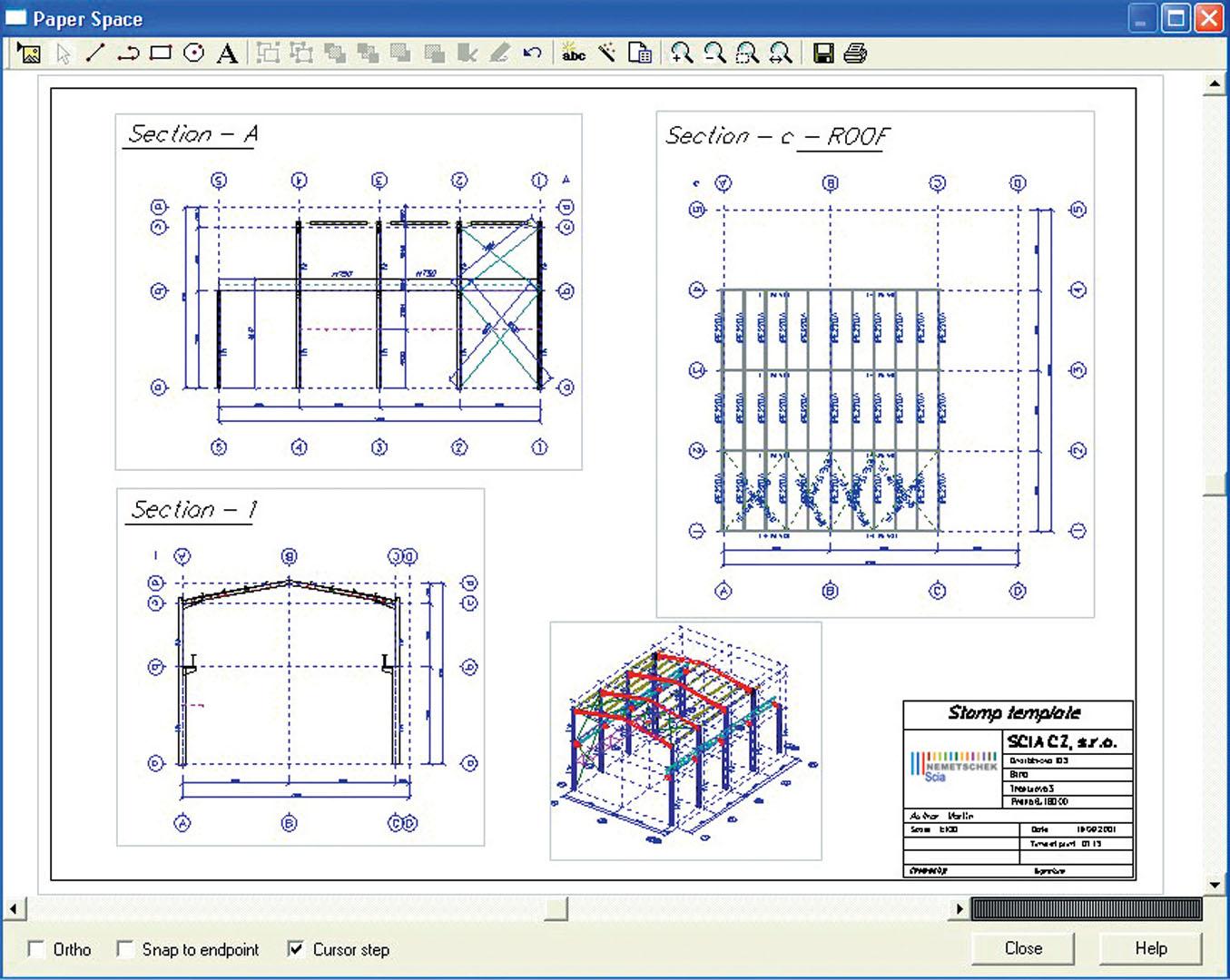
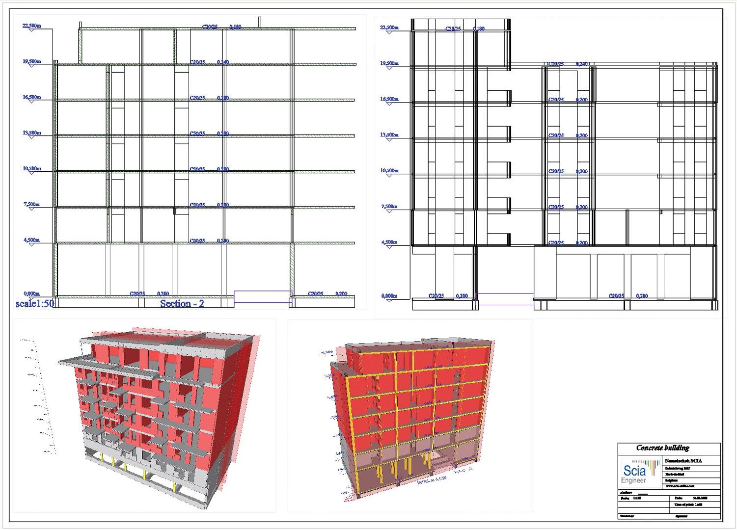
PaperSpace – tool for final General Arrangement drawings
In the PaperSpace editor you can compose the final drawing layout. The PaperSpace environment can be used to:
- Insert pictures from the gallery;
- Insert pictures from a saved file stored in internal SCIA Engineer format (ep3, ep2, epd),
- Insert bitmap image (bmp),
- Insert basic graphical entities, (lines, curves, texts),
- Insert plane section entities, i.e. section (line grid) or plan views (storey),
- Insert document items: i.e. all tables which are available in the document can also be inserted to the paper
The graphical environment of PaperSpace editor allows for fast preparation of stamps including inserted logos, automatic texts, frames etc. Any drawing can be saved as a template. Together with “automatic texts” (e.g. project name, author, date, time etc.,) this is a very efficient way of producing quality automatic drawings.
All pictures inserted to the drawing keep their 3D information, which enables additional changes to their properties (e.g. scale, rendering or hidden line mode, view direction).
Required modules:
- sen.00

Want to try SCIA Engineer yourself?
Explore how our software and services can help you optimise your work and boost your productivity. Try it for yourself with a free 30-day software trial.
Download a free 30-days full trial