General
ALLPLAN Product Frame in SCIA Engineer
Easy recognition of products from ALLPLAN family
The header of SCIA Engineer software has been updated to have a layout that is consistent with other ALLPLAN software.

Modelling & Loading
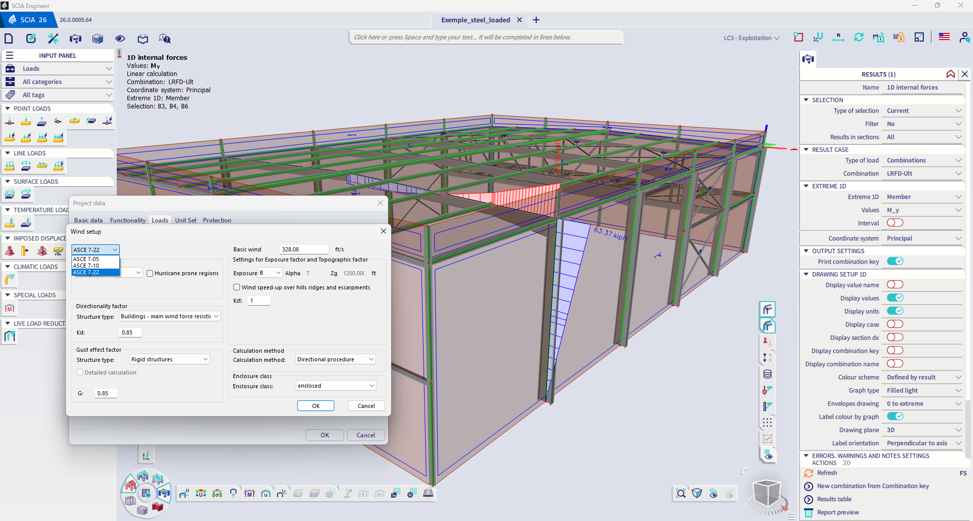
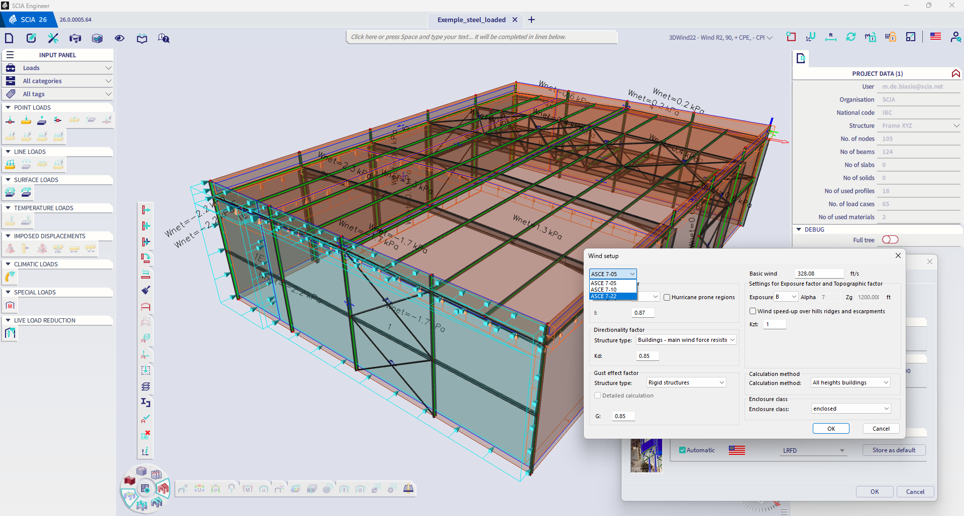
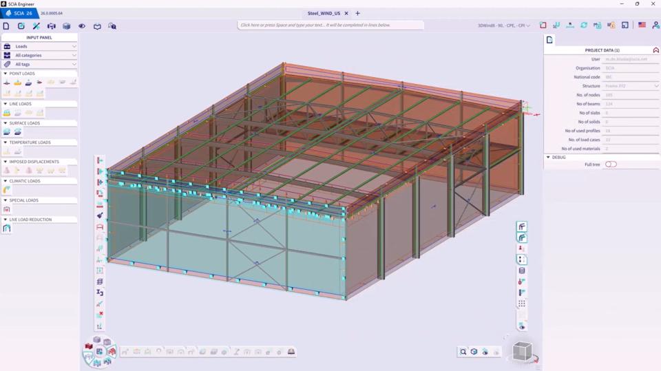
3D wind load engine for ASCE 7-22
Engineers designing according to the US codes can now take the full advantage of the wind load generator engine
The 3D wind load engine enables engineers to rapidly apply wind loads on structures, eliminating the need for time-consuming manual modelling of the that type of load.
The existing wind load engine has been updated, and it now generates loads in compliance not only with Eurocodes, but also with the latest US design code ASCE 7-22.
Analysis
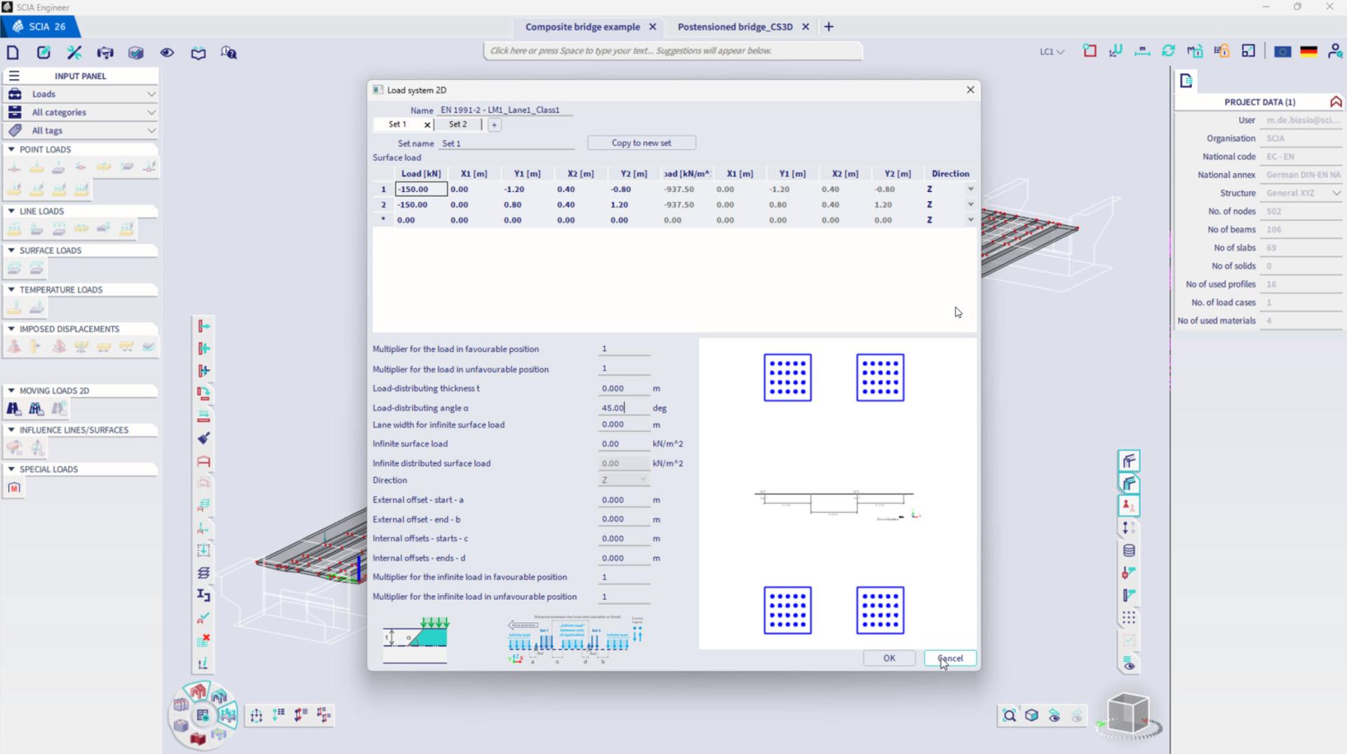
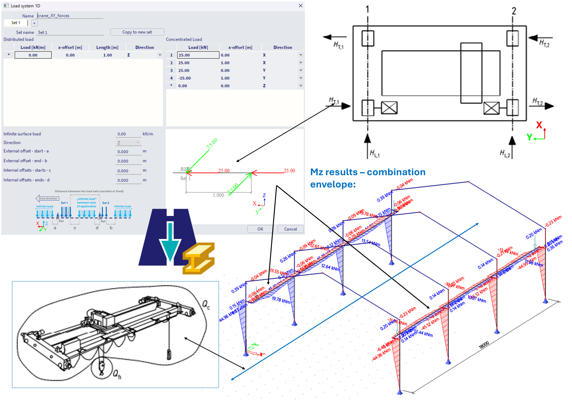
Moving loads
Extremely time-saving in presence of moving load systems
This feature solves the problem of dealing with a very large number of load combinations when the structure is subject to load systems that can assume different positions (traffic on a bridge, cranes in industrial facilities, crowds walking across slabs ...). Indeed, dealing with great many load combinations severely lengthens both the analysis and postprocessing time.
Leveraging the theory of influence lines and surfaces, this feature allows the engineer to quickly and automatically identify the worst-case position(s) of the load system before running the calculation. Therefore, the engineer can limit the analysis and postprocessing tasks to a limited number of worst-case scenarios, thus avoiding computing and post-processing negligible and non-critical load situations.
Footfall analysis
In-depth analysis of buildings with large open areas, footbridges and structures with lightweight floors
The footfall analysis determines the structure's dynamic response — such as acceleration, velocity, and response factor — to loads induced by human activity.
In buildings featuring large, open spaces — such as offices, shopping centres, stadiums, and footbridges — or in structures with lightweight floors (e.g. composite floors) or in buildings with sensitive equipment, vibrations caused by human activity can lead to discomfort or operational problems. Footfall analysis allows engineers to evaluate how the structure responds to these human-induced vibrations. With the insights gained from this analysis, engineers can adjust the structural design early in the project to keep vibrations within acceptable limits, ensuring occupants’ comfort and protecting sensitive equipment. This proactive approach helps avoid costly modifications after construction that might otherwise be required to address unsatisfactory structural performance.

![[EN] footfall analysis](/sites/default/files/styles/embed_large/public/images/2025-10/Footfall%20analysis-video.jpg?itok=bXYfCS-_)
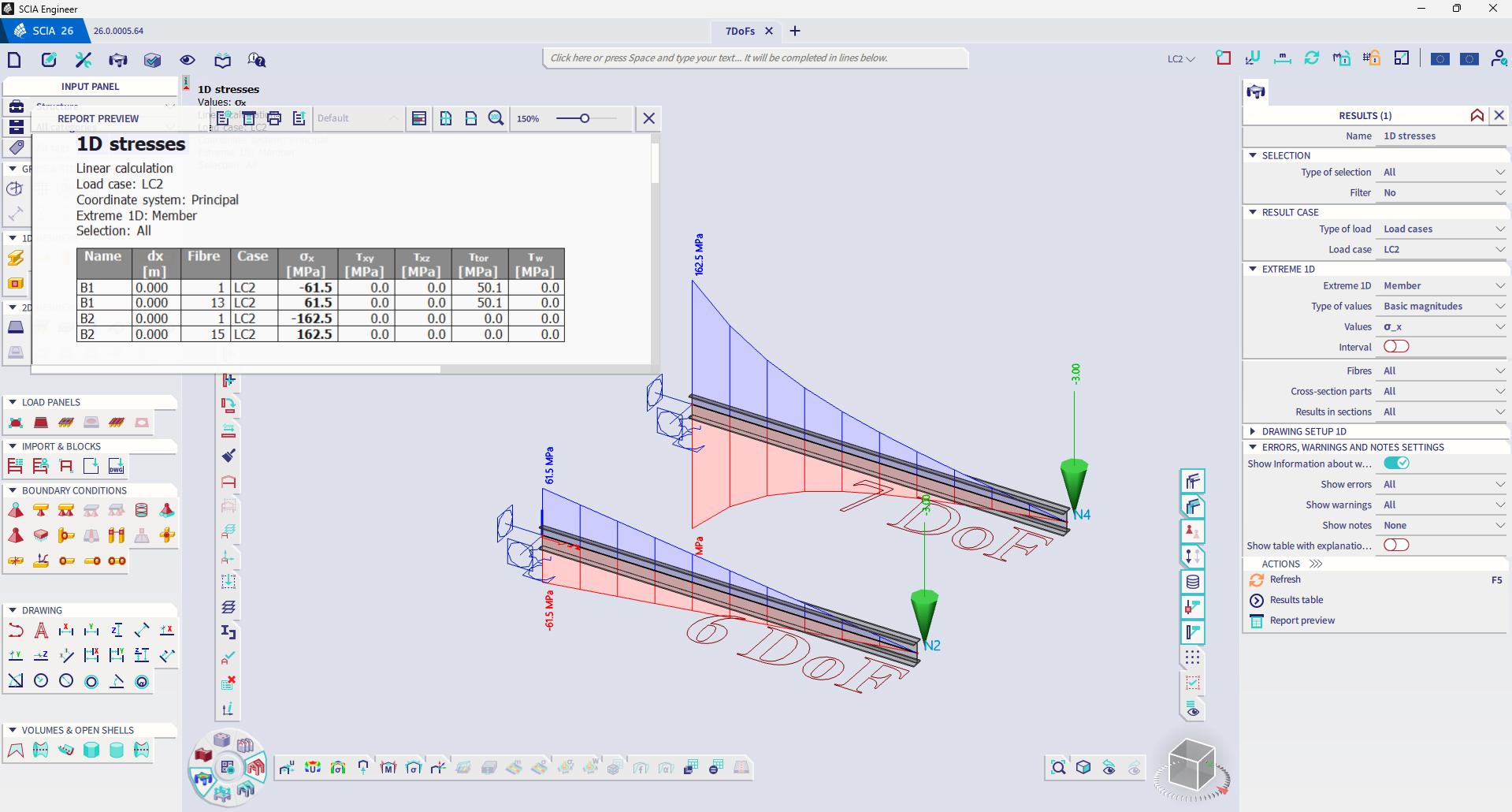
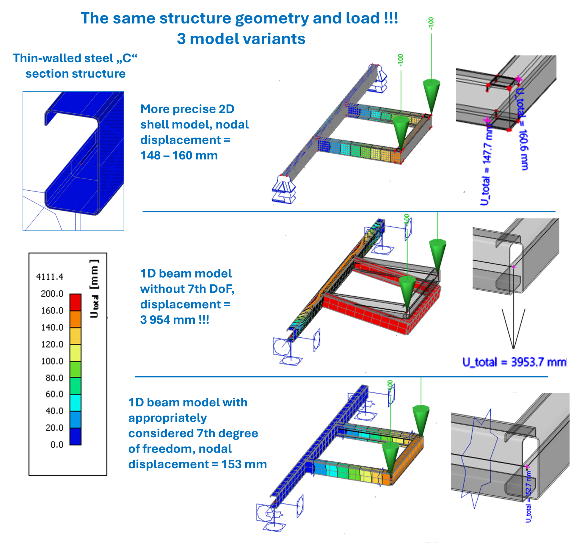
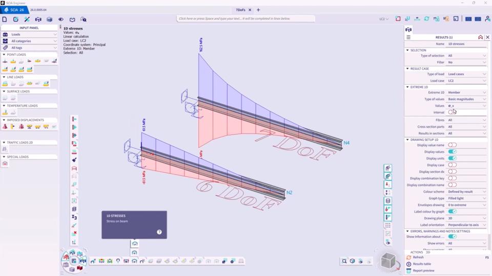
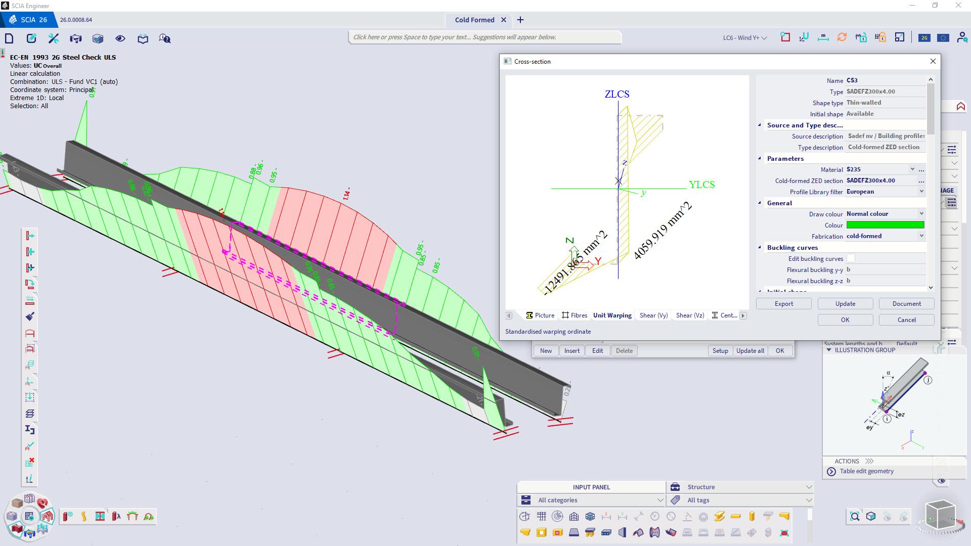
Beam finite element accounting for warping (7th degree of freedom)
In-dept analysis and accurate design of thin-walled or open-section beams and elements exposed to significant torsion
This feature introduces a new type of finite beam element that can account for an additional degree of freedom (warping). It allows for accurate modelling of slender or thin-walled beams, open-section beams, and structures subjected to significant torsion or complex loading. This approach is important especially for bridges, steel girders, or structures with non-standard cross-sections, where warping and distortional effects play a significant role in the structural response.
As a result, engineer gets more accurate predictions of stresses and deformations in cases where traditional beam elements are inadequate.
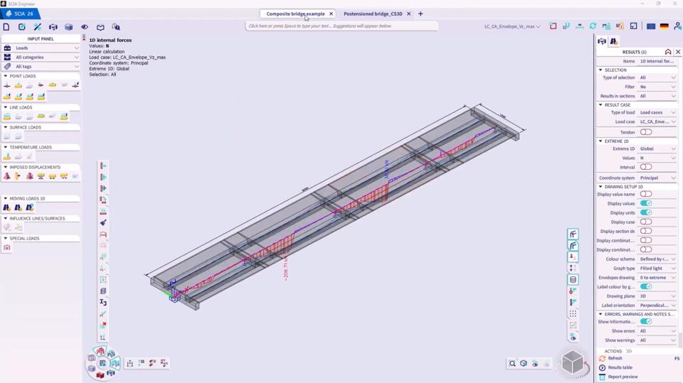
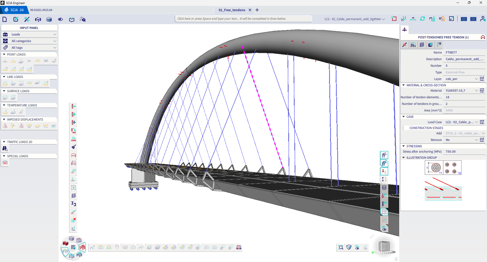
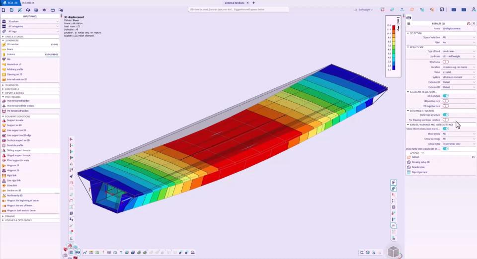
External tendons
Reliable and accelerated modelling, analysis, optimisation of structures incorporating external (unbonded) tendons
External tendons represent a common strategy for reinforcing of bridges, slabs, and other large-scale concrete structures.
This new functionality allows the use to effectively model the three-dimensional geometry of external tendons for beams, slabs, walls, and plates. Tendon paths, both straight and curved, can be defined either manually or, preferably, imported from DWG or DXF files.
The analysis supports staged construction, enabling the effective simulation of tendon installation, tensioning, and grouting processes. The comprehensive results include tendon profiles, stress distributions, prestress losses, and their impacts on the overall structure, all visualized in 3D and exported to the project documentation.
Code Design
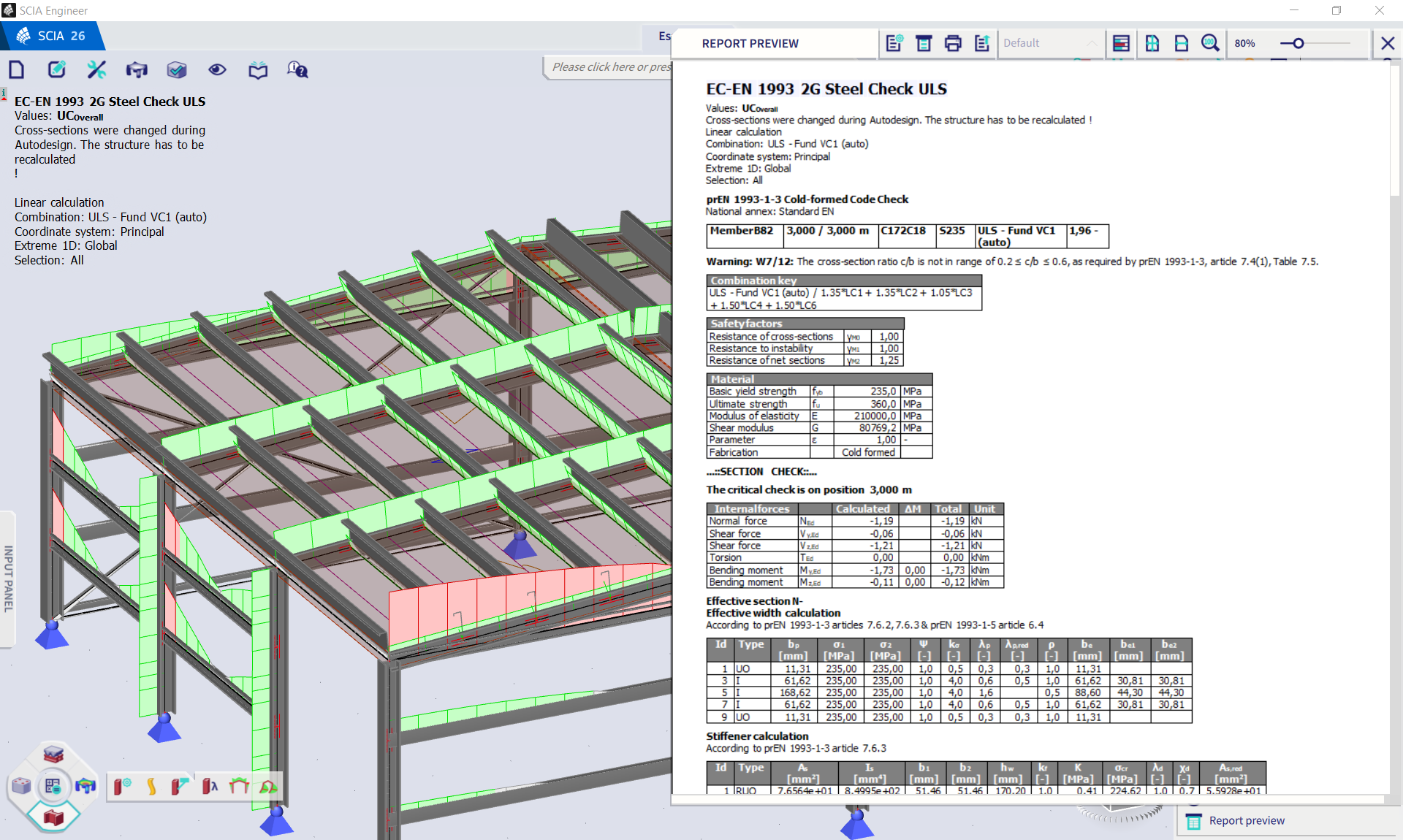
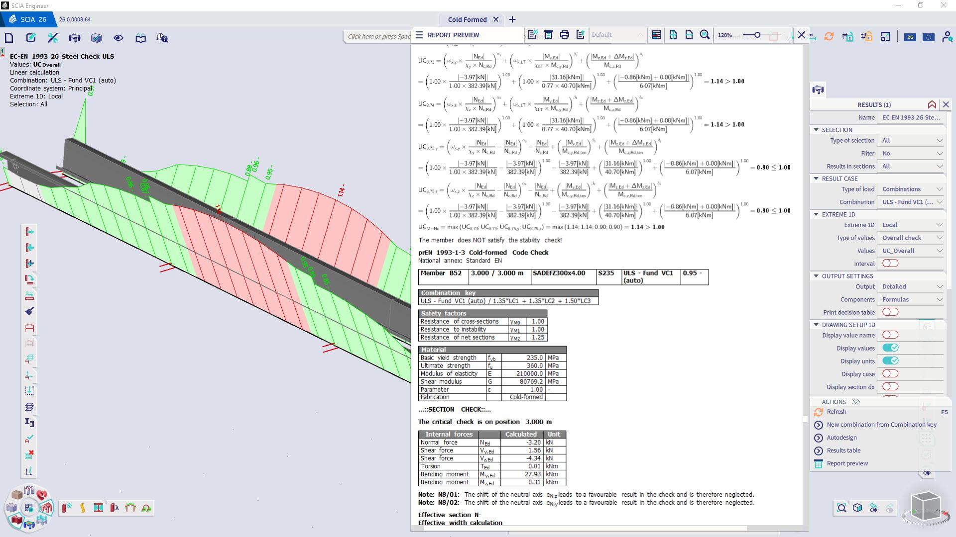
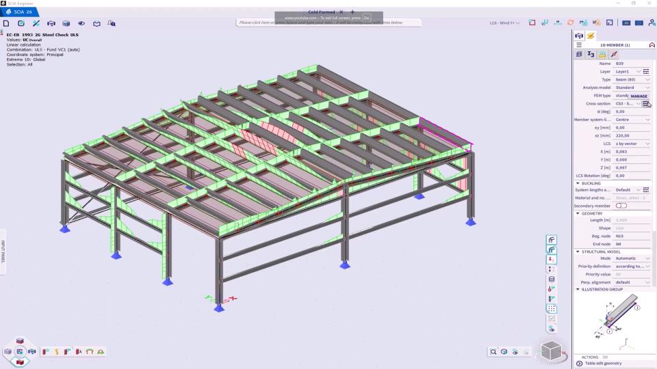
Steel 2nd generation EN 1993-1-1 & EN 1993-1-3
Compliance with the coming 2nd generation of Eurocodes
A brand-new generation of design rules is approaching at a fast pace. The expected timeline is for the 2nd generation to come into action in 2027 and to become mandatory for design by 2028.
SCIA Engineer has always provided its users with automated verifications according to the latest Eurocode guidelines, as well as a very strong solution for steel design, making it the chosen software of many European steel designers. The implementation of the 2nd generation steel design will be an almost exact copy of the current workflow for Eurocode steel design, with a few menu enhancements and added features to further enhance the steel design in SCIA Engineer. In the 2nd generation environment, the engineers can design according to updated EN1990 rules for combinations, EN 1993-1-1 for basic steel design and EN 1993-1-3 for cold-formed steel.
The switch between the codes is very easy. With a few clicks the engineers can convert their projects between the two generations of the code, compare results, and analyse changes with the help of the detailed output that is available for steel design checks.
Moreover, the national annex and steel setup menus are both upgraded to the newest menu design. In addition, it will be now possible to ignore force components with or without a user defined threshold, which has been already possible for concrete verifications.
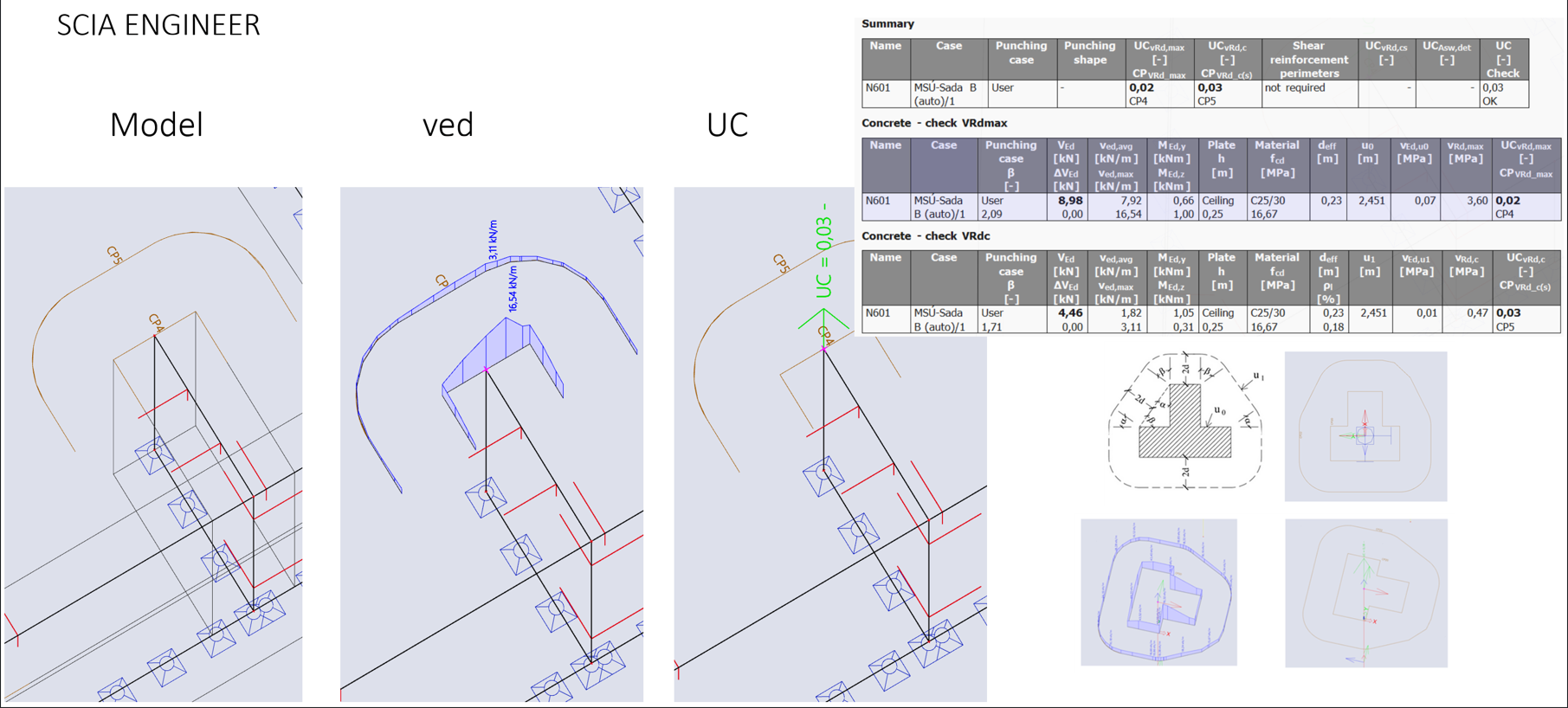
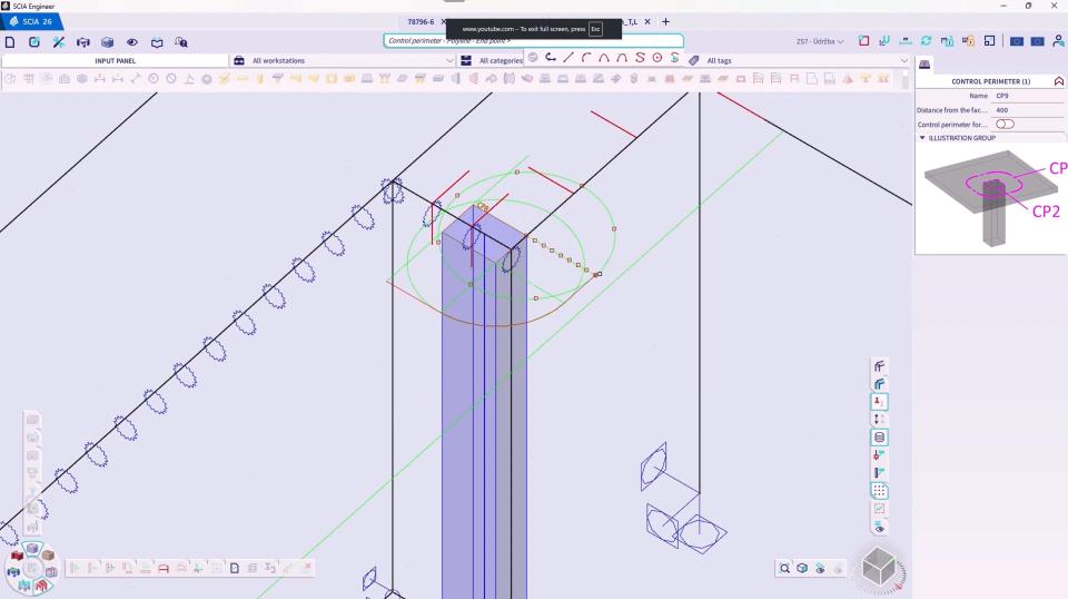
Punching shear check for walls
Ability to execute punching checks for any slab and subregion interacting with a column of any shape or with a wall
Until now, punching shear design in SCIA Engineer was limited to circular and rectangular column shapes.
However, it is often necessary (and often requested by customers) to perform a punching shear design for end of walls and corners or even for any shape of cross-section. In SCIA Engineer 26.0 punching checks can now also be executed for corners, end of walls and any shape of cross-sections.
The control perimeter is generated automatically for standard column shapes. For non-standard shapes and walls, the user can draw the control perimeter manually. For both user-defined and automatically generated control perimeters, the forces are calculated and a punching shear check is performed.
This allows the users to check whether the required longitudinal reinforcement of the slab or foundation is sufficient to resist the local shear force at the support. If necessary, the calculation and design of the required shear reinforcement around the support can then be carried out.
All parts of the punching check are executed according to EN 1992-1-1.
This feature allows customers to execute punching checks for all slabs and subregions interacting with any column shape or wall.

Want to try SCIA Engineer yourself?
Explore how our software and services can help you optimise your work and boost your productivity. Try it for yourself with a free 30-day software trial.
Download a free 30-days full trial