Highlights
- Smoothly integrated with other analysis and design features, the fire design functionality complements the essential set of tools available in SCIA Engineer for steel structures.
- Structures can be designed for fire conditions based on both first- and second-order calculations.
- Libraries are provided for fire curves and heat insulations; these can be extended by users.
- Clear and comprehensive reporting at different levels of detail: from a brief summary per member to a detailed calculation report with formulas and references to the articles in the code.
The Steel fire resistance design sensd.05 module provides stress and stability checks for steel members under fire conditions. The checks can be performed according to EN 1993-1-2, SIA 263 or NEN 6072, both in the resistance and in the temperature-time domain.
SCIA Engineer determines the evolution of gas and material temperature over time, based on the rules of the code and the selected fire curve, type of exposure of the members, and fire protection, if defined. The modified resistances at elevated temperature are derived. The steel fire check also follows the recommendations published in ECCS N°111.
Benefits
Fire resistance checks are performed in the same work environment as the Steel code check at ambient temperature.
- Customised fire resistance data can be defined for the whole structure, or per member: required fire resistance (R15, R30, R60), heat insulation, etc.
- Detailed fire scenarios can be simulated, with customised exposure (3- or 4-sided), fire protection layers and consideration of shadowing effect for unprotected members;
- Alternative flexural buckling length factors can be specified for the fire situation;
- Up-to-date section factors Am/V and [Am/V]b and are provided for each supported cross-section in the library;
- Cross-section classification is performed specifically for fire situations;
- The programme cycles through the defined load case/combinations to derive utilisations and shows critical members;
- The module includes a cross-section optimisation feature: for both protected and unprotected members, ideal sections are obtained based on a target utilisation level specified by the user;
- An iterative procedure may be applied to determine the critical steel temperature in the temperature domain. In this case, SCIA Engineer ensures that the critical temperature corresponds to 100% utilisation; the non-iterative simplified approach uses the initially calculated utilisation factor μ.
- A few general SCIA Engineer features make it simple to select members with similar fire insulations or other settings, members with similar utilisations, etc.
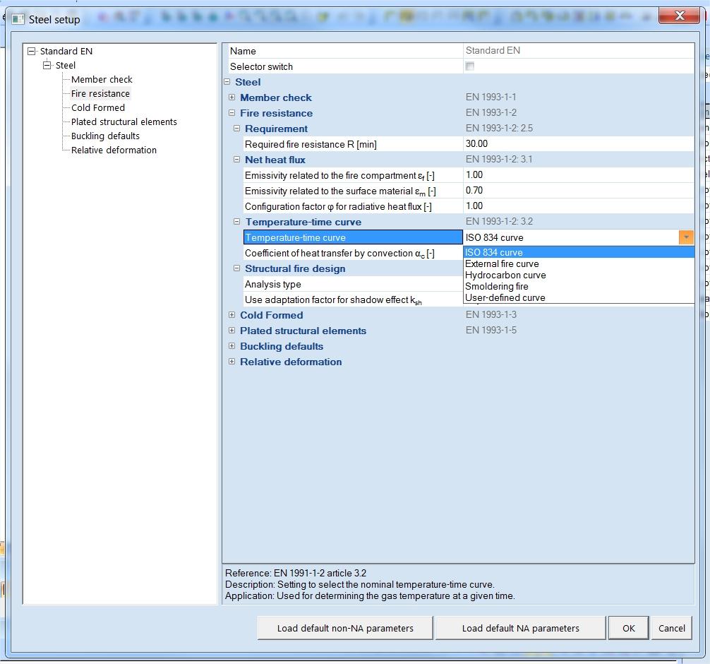
Fire curves and other settings
The following temperature curves are included in the software:
- ISO 834 curve;
- external fire curve;
- hydrocarbon curve;
- smouldering fire curve;
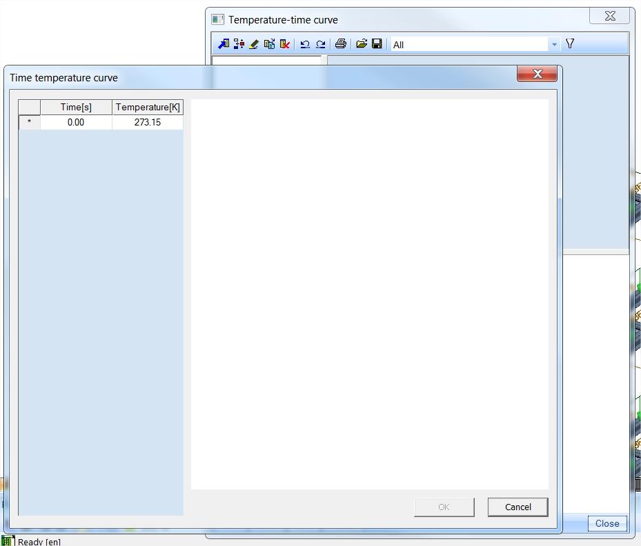
User-defined temperature curves may be defined and used as well.
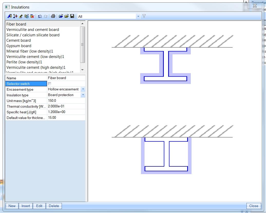
You may specify fire protection. Built-in types of heat insulation include:
- fibre boards, vermiculite/silicate/cement boards, gypsum boards;
- mineral fibre;
- vermiculite cement, perlite, gypsum sprays;
- intumescent coatings.
You may also select, for the whole structure or per member:
- fire exposure per section (all sides, three sides only);
- net heat flux parameters, e.g. αc coefficient of heat transfer by convection, emissivity, etc.;
- separate buckling length factors for the fire situation;
- fire resistance safety factors (values according to the Eurocode, SIA and NEN codes are available by default);
- general data related to LTB, diaphragms, shear buckling stiffeners.
Supported codes
- EN 1993-1-2:2005
- SIA 263:2003
- NEN 6072:1991
Supported cross-sections
Fire resistance verification is supported for the following cross-sections:
- symmetric and asymmetric I-, L-, U-, T-sections;
- rectangular and circular hollow or solid sections;
- single and double angles;
- composed steel welded sections;
- sections with haunches, I-sections with variable height;
- single plate cold-formed steel sections;
- numerical sections with manually defined section properties;
- built-in beams of types IFBA, IFBB, SFB and THQ.
Performed checks
EC3-1-2:
- Cross-section classification according to art. 4.2.2;
- Resistance of tension members: art. 4.2.3.1;
- Resistance of class 1, 2 and 3 compression members: art. 4.2.3.2;
- Resistance of class 1 and 2 beams: art. 4.2.3.3;
- Resistance of class 3 beams: art.4.2.3.4;
- Resistance of class 1, 2 and 3 members subject to bending and compression: art. 4.2.3.5.
- Resistance of critical temperature: art. 4.2.4;
- Resistance of check for class 4 members (Annex E).
SIA 263:2003
- Classification of cross section: art. 4.8.5.2;
- Resistance of tension members: art. 4.8.5.4;
- Resistance of compression members (class 1, 2 or 3): art. 4.8.5.5;
- Section and stability checks according to Chapter 4.8.5;
- Resistance of beams (class 1, 2, 3): art.4.8.5.6., art. 4.8.5.7., art. 4.8.5.8;
- Resistance of members (class 4): art. 4.8.5.9.
NEN 6770/6771:
- Cross-section classification according to art. 4.2.2;
- Resistance of tension members: art. 4.2.3.1;
- Resistance of compression members (class 1,2 or 3): art. 4.2.3.2;
- Resistance of beams (class 1,2): art. 4.2.3.3;
- Resistance of beams (class 3): art.4.2.3.4;
- Resistance of members (class 1,2,3) subject to bending and compression: art. 4.2.3.5;
- Critical temperature: art. 4.2.4.
Reporting
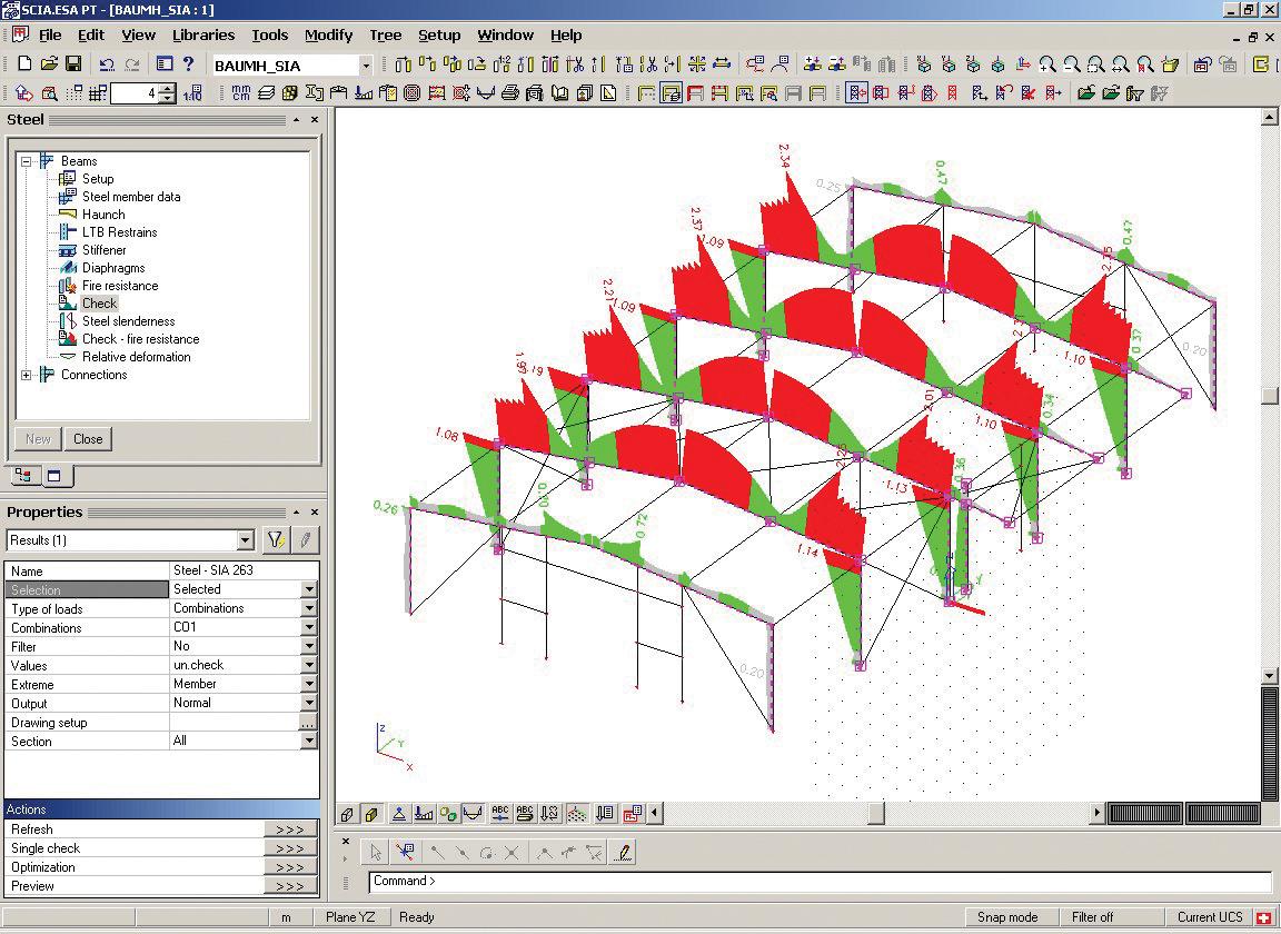
The Steel fire design module benefits from an interactive reporting interface, where the results of the design are easily accessible in various forms:
- colour-coding utilisation diagrams in the 3D scene helps to quickly find problems anywhere in the structure;
- the design outcome for all members is easily printable in table form via the Brief report or via Table Results;
- a Summary report per member summarised important parameters of the design and all checks on a single page;
- a Detailed report shows all calculations as formulas (or tables, if the user prefers) with references to the used articles from the code, letting you follow and verify the logic and steps of the design;
- the Summary and Detailed report are directly accessible by double clicking on the rows of Table Results; in this way, you quickly make the connection between details of the calculation and the members visualised on the screen.
- errors, warnings and notes can be shown interactively by hovering on specific members in the 3D scene;
- a detailed overview of the section classification and effective section derivations can be added to the Engineering report as well;
- at all times when plotting results, the selected settings (e.g., selected load combination, member names, type of calculation and extremes) are displayed via the Result Legend in the top left corner;
- besides the overall utilisation, you can plot specific checks onto the members using the Result Components.
The benefit of these reporting features is twofold: on one hand, the design process is accelerated, and on the other hand, it is possible to create project notes that are complete and transparent to convince any third-parties and controlling authority about the quality and scope of the performed structural design verifications.
Required modules:
- sen.00

Want to try SCIA Engineer yourself?
Explore how our software and services can help you optimise your work and boost your productivity. Try it for yourself with a free 30-day software trial.
Download a free 30-days full trial