Model a typical composite beam
Steel-concrete composite beams take advantage of the inherent benefits of concrete (strong in compression) and steel (strong in tension). Composite beams are usually hot-rolled or fabricated steels sections that act compositely with the floor slab. Often the slab is formed by profiled steel decking acting compositely with in-situ concrete. Composite interaction is achieved by attaching shear connectors to the top flange of the beam.
In SCIA Engineer downstand composite beams using steel decking can be modelled in two ways
- method 1: Composite deck method;
- method 2: Ribbed slab method.
For the analysis and design, both options give the same results.
Method 1: composite deck method
Benefits of this modelling method are:
- More flexibility when modelling floor beam layouts;
- Useful for irregular floor geometries;
- Can model several bays (or whole floors) using one composite deck member.
Outline procedure:
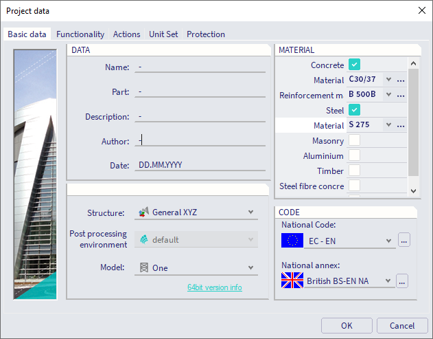
- Define a concrete and steel material in the 'Project Data' dialog (via Main menu > File > Project settings) to activate the ‘Composite’ module and 2D member type 'Composite Deck':
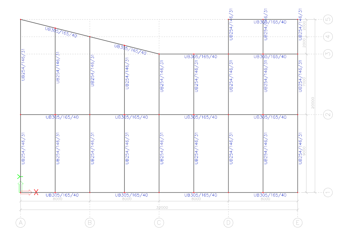
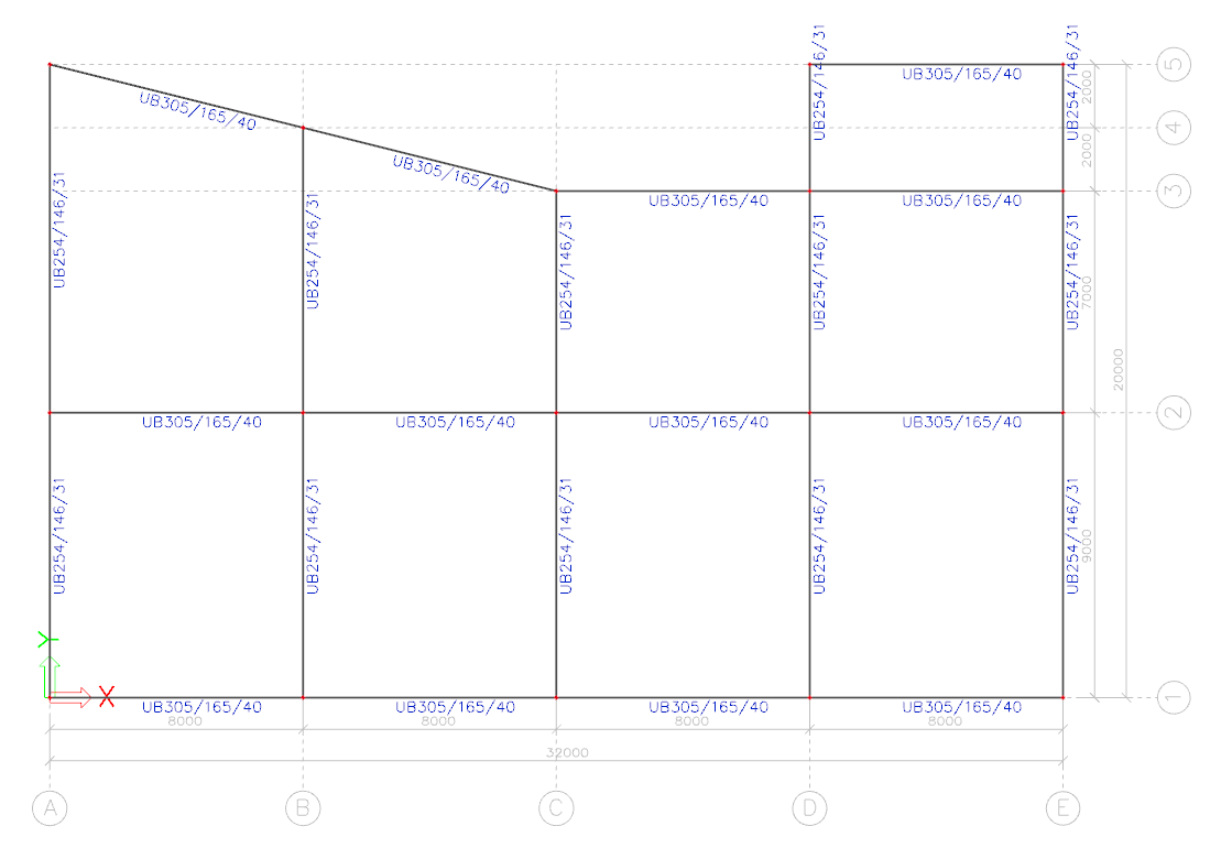
- Create your floor beam layout using 1D members. The figure below shows a floor beam arrangement example (plan view):
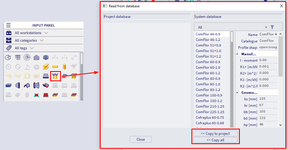
- To create the floor slab select 'Composite Deck' (Input panel > workstation Structure > category 2D Members). If this is the first composite deck member in your model, then SCIA Engineer will prompt you to select a steel decking profile from a library of proprietary products. You can create a custom profile if required:
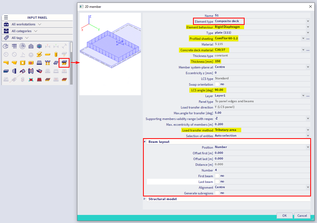
- Adjust the composite deck properties (e.g. thickness, decking and concrete material) to suit your design:
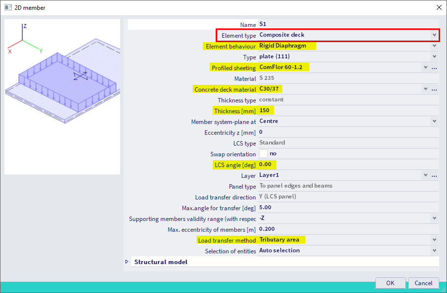
- Element Behaviour: control the in-plane behaviour of the composite deck, i.e. the diaphragm action for transferring lateral loads. See following FAQ for more information: Model a composite deck
- Profiled Sheeting: select the profiled steel decking product that will form part of the composite deck.
- Thickness: define the total thickness of the composite slab.
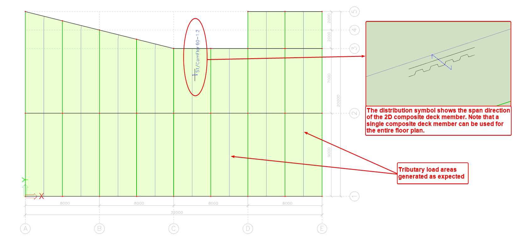
- LCS angle: define the span direction of the composite deck, 0.0 degrees corresponds to the local x-axis of the 2D member.
- Load Transfer Method: first preference should be ‘Tributary Area’ for composite beams. Only use one of the ‘Accurate FEM’ methods if a tributary load area cannot generate correctly.
- Create the composite deck as you would any 2D member. Using the Composite Deck Method, you can create one member for the entire floor:
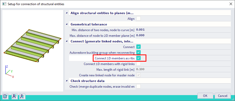
- Select the composite beams and the corresponding composite deck and connect the 1D members as ribs (via Main menu > Edit > Modify > Connect members/nodes). This command will connect the beams to the composite deck as plate-ribs. This option is available as well in the Calculation dialog.
Important note about eccentricities: After connecting the beams as ribs, the beams and slab will not mimic the real-world construction, i.e. the ribs are not shown as a downstand beams. No eccentricity is required to calculate the correct results for composite design checks according to design codes (e.g. EN 1994-1-1). To display the real-world construction without affecting the FEM analysis results, see following FAQ: Visualise composite beams
Method 2: ribbed slab method
Benefits of this modelling method are:
- Defines the composite slab and secondary beams in one command operation;
- Suitable for regular floor geometries, e.g. repeating column grids;
- Quick and easy to adjust the number of secondary beams per bay.
Outline procedure:
- Define a concrete and steel material in the 'Project Data' dialog to activate the ‘Composite’ module and 2D member type 'Composite Deck'.
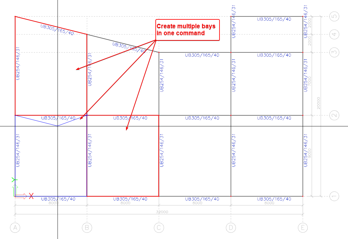
- Create your floor bay using 1D members to connect the columns. Intermediate beams will be defined later. The figure below shows an example floor bay layout.
- Create a 'Ribbed Slab' member (Input panel > workstation Structure > category 2D Members) and set the ‘Element Type’ property to ‘Composite Deck’. If this is the first composite deck member in your model, then SCIA Engineer will prompt you to select a steel decking profile from a library of proprietary products. You can create a custom profile if required. Adjust the 2D member settings to suit your design. Use the 'Beam Layout' fields to set out the intermediate beams.
- Element Behaviour: control the in-plane behaviour of the composite deck, i.e. the diaphragm action for transferring lateral loads. See following FAQ for more information: Model a composite deck
- Profiled Sheeting: select the profiled steel decking product that will form part of the composite deck.
- Thickness: define the total thickness of the composite slab.
- LCS angle: define the span direction of the composite deck, 0.0 degrees corresponds to the local X-Axis of the 2D member.
- Load Transfer Method: first preference should be ‘Tributary Area’ for composite beams. Only use one of the ‘Accurate FEM’ methods if a tributary load area cannot generate correctly.
- Create a composite deck in each floor bay. Define the composite decks as you would any 2D member:
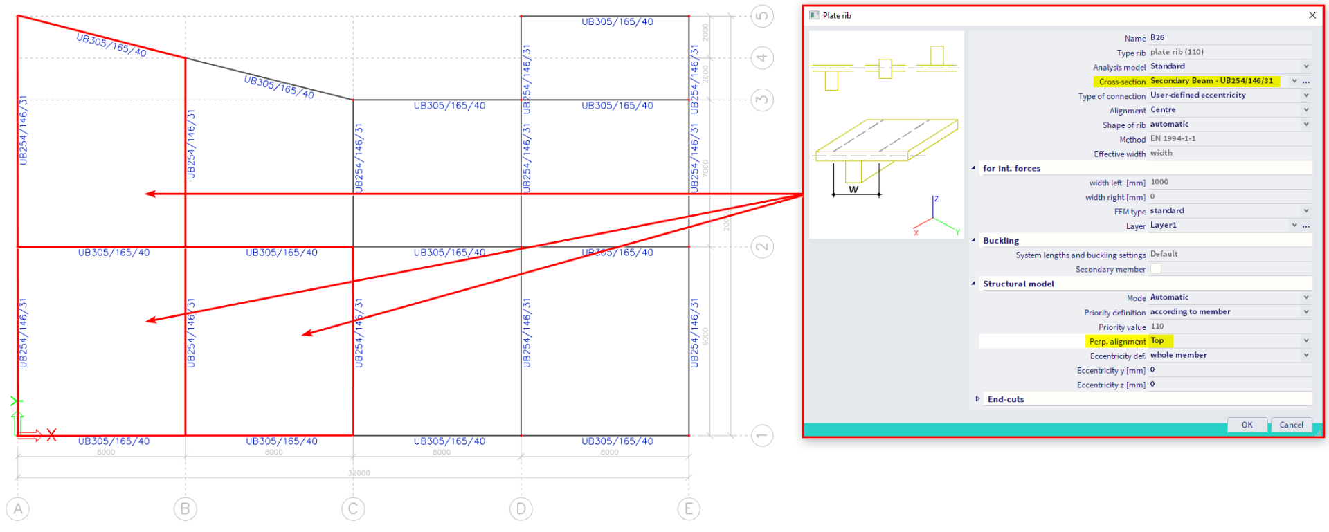
- Adjust the properties for the intermediate composite beams for the bays created in the previous step. You can also adjust the perpendicular alignment in the 'Structural Model' to replicate the real-world eccentricity of the downstand beam.
- Due to the 'Beam Layout' settings in step 3, only the intermediate beams are connected as ribs. The secondary beams on column lines will need to be connected as ribs if you want them to be treated as composite beams (see next step).
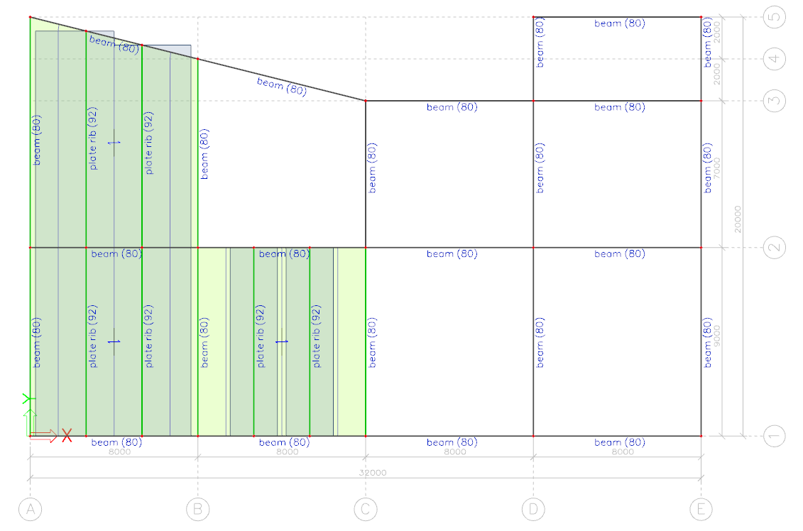
- Select the beams and the corresponding composite decks (if you do not want to connect all entities) and connect the 1D members as ribs. This command will connect the beams to the composite deck as plate-ribs. This option is available as well in the Calculation dialog.
Important note about eccentricities: After connecting the beams as ribs, the beams and slab will not mimic the real-world construction, i.e. the ribs are not shown as a downstand beams. No eccentricity is required to calculate the correct results for composite design checks according to design codes (e.g. EN 1994-1-1). To display the real-world construction without affecting the FEM analysis results, see following FAQ: Visualise composite beams