Shrinkage effects in nonlinear analysis
When concrete structures are designed, a linear analysis is usually not fully sufficient. There are several other aspects influencing the behavior of the structure mainly from the serviceability point of view. These effects are mainly:
- Concrete cracking
- Creep and shrinkage
The cracking of concrete is usually an irreversible effect which appears when the tensile strength of the concrete is exceeded. The structure could however still be durable and reliable with cracks if those are below the code given limits. This article is mainly about the notification of these effects during design with a focus on shrinkage.
Shrinkage effect
Creep and shrinkage phenomena are the most important time-dependent material characteristics of concrete. When concrete is placed in situ, the cement starts to hydrate using the free water in the mixture. Usually, the water exits the concrete, and the process of drying shrinkage is starting. This is the reason why the concrete must be cured especially in the early stages after casting. Without a special curing process, additional stresses are presented inside of the concrete which can lead to shrinkage cracking.
The second part of shrinkage is autogenous shrinkage when the concrete consumes its own water during the hardening process. Here the size of the autogenous shrinkage depends mainly on the water cement ratio (w/c). When the w/c ratio is lower, then the autogenous shrinkage is higher.
There are several aspects affecting the progress of the shrinkage as follows:
- Beginning and duration of curing
- Amount and position of reinforcement
- Dimension of the structure
- Relative humidity and temperature
- Cement type
- And others
Theoretical background
As has been mentioned above, the total shrinkage (εcs(t,ts)) strain is composed from two parts:
- Drying shrinkage (εcd(t,ts))
- Autogenous shrinkage (εca(t))
εcs(t,ts) = εcd(t,ts) + εca(t)
The calculation of both strains is described directly in EN1992-1-1[1].
SCIA Engineer [2] considers both parts of shrinkage effects automatically by default. (This can be disabled if needed in Concrete settings / Concrete member data). The value of shrinkage is calculated based on the predefined time of curing and time of the loading.
The deflections caused by shrinkage are calculated based on the strain and curvatures caused by the shrinkages for the uncracked and fully cracked cross-section. The whole procedure can be expressed in three steps:
Calculation of shrinkage forces
The forces caused by shrinkage are calculated according to the formulas below based on the shrinkage strain.
- Nshr = -εcs(t,ts)·CoefReinfΣ(Esi·Asi)
- Mshr,y = Nshr·eshr,z
- Mshr,z = Nshr·eshr,y
Where:
-
eshr,y = Σ(Esi·Asi)/ Σ(Esi·Asi·ysi) - tiy
-
eshr,z = Σ(Esi·Asi)/ Σ(Esi·Asi·zsi) - tiz
-
Esi - is modulus of elasticity of i-th bar of reinforcement
-
Asi - is area of reinforcement of i-th bar of reinforcement
-
ysi – position of i-th bar of reinforcement from centre of gravity of cross-section in y-direction
-
zsi – position of i-th bar of reinforcement from centre of gravity of cross-section in z-direction
-
tiy – distance between centre of gravity transformed uncracked/cracked cross-section and centre of gravity of concrete cross-section in y-direction
-
tiz – distance between centre of gravity transformed uncracked/cracked cross-section and centre of gravity of concrete cross-section in z-direction
Calculation of strain and curvature caused by shrinkage
Strain and curvature caused by shrinkage are calculated for each element and these values are calculated for both states (uncracked and cracked cross-section). Calculation of strain caused by shrinkage:
- εsh = -εcs(t,ts)·CoefReinf·Σ(Esi·Asi)/(Eceff·Ai)
Calculation curvature around y- and z-axis caused by shrinkage
- (1/ry) = -εcs(t,ts)·CoefReinf·Σ(Esi·Asi·(tiz-zsi))/(Eceff·Iiy)
- (1/rz) = -εcs(t,ts)·CoefReinf·Σ(Esi·Asi·(tiy-ysi))/(Eceff·Iiz)
Calculation of stiffnesses for shrinkage
The stiffness of the uncracked / cracked cross-section for shrinkage is calculated from the strain and curvatures caused by shrinkage by using the total level of load (total load combination) and then used in the finite element calculation
-
bending stiffness around y-axis EIy = Mtot,y/(1/ry)
-
bending stiffness around z axis EIz = Mtot,z/(1/rz)
-
axial stiffness EA = Ntot/εsh
Note: As indicated above, as a simplification the total forces are used for the calculation of the stiffnesses for the FEM analysis instead of the forces caused by shrinkage.
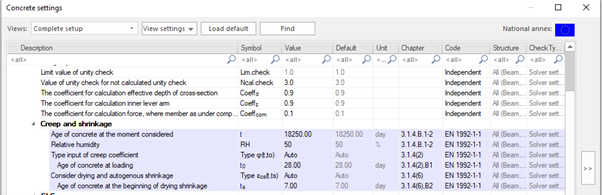
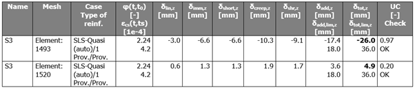
Results presentation
The output of the deflection results can be seen graphically in the 3D window and also numerically via the Brief, Standard or Detailed output. The following picture shows an example of the Brief table which represents the following values:
- creep factor φ(t,t0)
- shrinkage strain ε(t,ts)
- deflection caused by creep (δcreep)
- deflection caused by shrinkage (δshr)
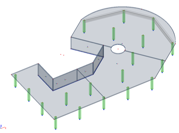
Case study
The effect of shrinkage is illustrated on a medium-sized project. The structure has a slab thickness of 270 mm from concrete C30/37, which is loaded by a permanent load of 2,5 kN/m² and a variable load of 3,0 kN/m². The reinforcement in both surfaces and directions is diam.12/200 mm in the span and above supports diam.12/100 with B500B. The concrete cover is 30 mm. The time of concrete curing is 7 days, the time of load application is 28 days. The time of investigation is 50 years. The relative ambient humidity is 50%.
A comparison is made between the results of the deflections coming from a linear and those of a nonlinear analysis, including concrete cracking and time dependent effects as a creep and shrinkage.
- Nonlinear deflection with cracking

- Nonlinear deflection with cracking and creep
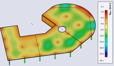
- Nonlinear deflection with cracking, creep and shrinkage

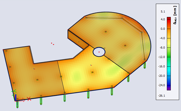

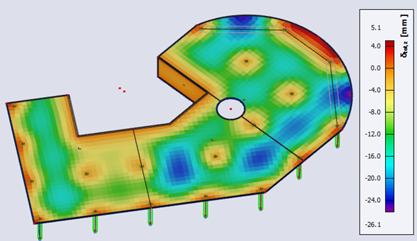
The previous graphical results can be summarized:
-
Linear deflection: maximal deformation of 4,2 mm
-
Nonlinear deflection with cracking: maximal deformation of 7,8 mm
-
Nonlinear deflection with cracking and creep: maximal deformation of 16,8 mm
-
Nonlinear deflection with cracking, creep and shrinkage: maximal deformation of 26,1 mm
Conclusions
As can be seen from the results, using merely a linear analysis is not sufficient for reinforced concrete structures. The effect of cracking gives almost 2x higher values compared to the linear deflection. Additionally, it is essential to consider also creep and shrinkage effects to obtain the real behavior of the structure. In case of creep only this leads to 4x higher results and when considering all effects together almost 7x. Neglecting such effects during design could lead to significant issues during the life cycle of the structure, especially a lower serviceability due to high deflections.
References
[1] EN1992-1-1 - Eurocode 2: Design of concrete structures - Part 1-1: General rules and rules for buildings
[2] www.scia.net