Define a variable surface load – e.g. soil or hydraulic pressure
You have to use a free surface load to define a variable surface load - e.g. soil or hydraulic pressure - on a 2D-element. How you can do this is explained in this article via two examples.
Example soil pressure on a wall
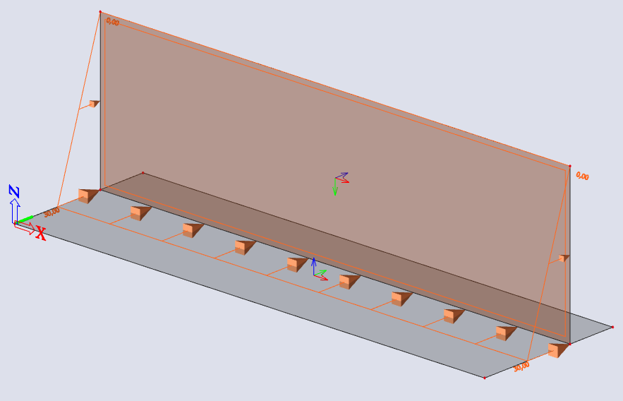
We start with a simple geometry.
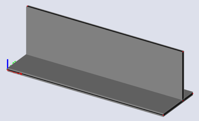
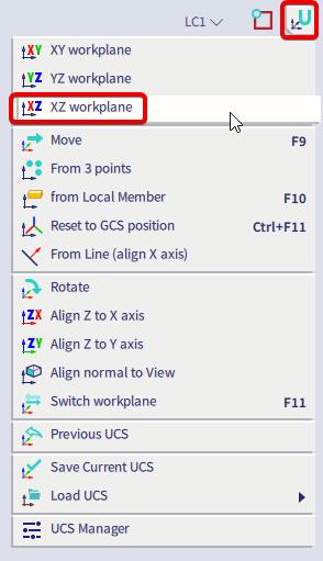
Since the geometry of a free load is always inputted in the active working plane (XY, XZ or YZ) of the current UCS. It is thus necessary to adapt the UCS in advance and set up the active working plane via 'coordinate system'.
For this example, we will set the UCS to the XZ plane.
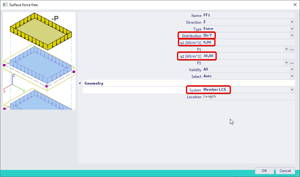
Next we will define the free surface load. This can be done by typing in 'free surface load' in the SCIA spotlight.

A variable distribution in the Y- or Z-direction (local axis) should be applied. If the direction of variation is not parallel to one of the axes, you can also use the "3 points" to use 3 nodes that define the geometry of the free load to define its variation.
Since the ‘member LCS’ option is selected, the loads are defined according to the LCS of the wall. In this case you should define positive values.
As soon as you confirm this window by clicking on ‘OK’, the free load can easily be defined by selecting the four corners of the wall.
You can change the direction of the variation with the values marked in red below.
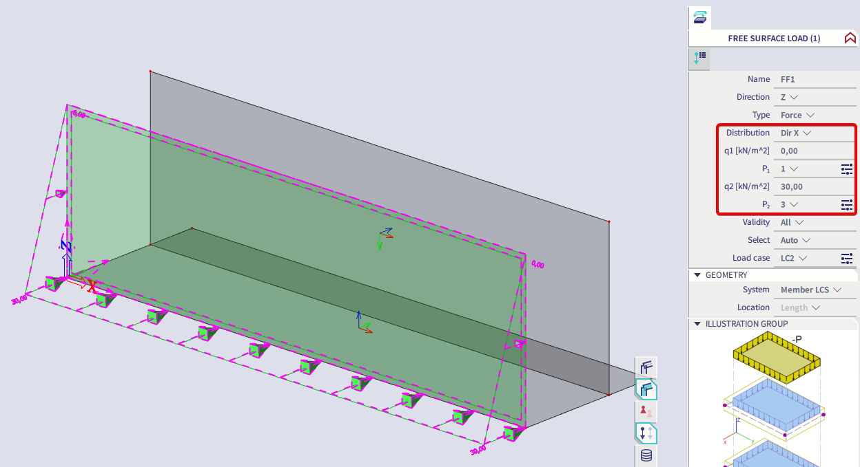
Note that the free load is projected onto the XZ plane and not on the wall itself.
Since this is the representation of the original load, we still need to create the generated load by executing the ‘Generate loads’ command within the ‘Actions’ menu that can be found in the properties window of the load. As soon as this step is executed, the generated load will be displayed according to the LCS of the member.
We also could have moved the UCS to the wall. This would have caused the original load to be drawn on the same location of the wall. Then we could have used 'Validity: Z=0' to make sure that only the wall would be selected to generate the load onto.
Remark:
In this example, we applied the ‘Auto’ option for the ‘Select’ parameter. This means SCIA Engineer will automatically generate loads on all the elements, which are cut by the projection of the free load. The ‘Select’ option can be applied for this parameter as well, which means you have to select the members on which the free surface load should be applied. This can be done by executing the ‘Update 2D members selection’ command that can be found in the ‘Actions’ menu.
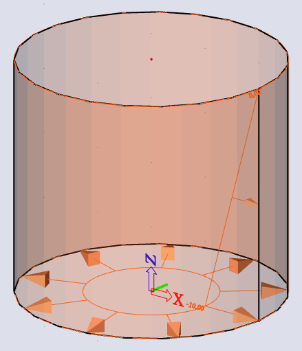
Example hydraulic pressure in a cylindrical tank
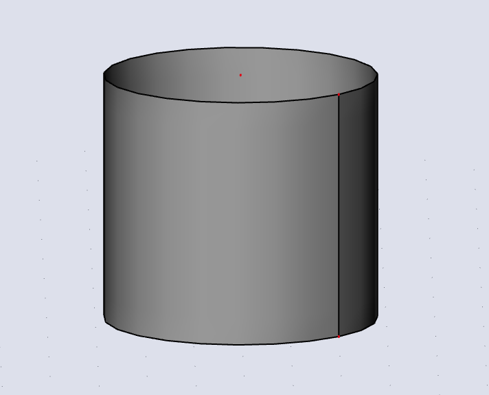
We'll start with a cylindrical geometry. This can be done by using the 'wall' command, and then choosing the circle option.

Enter the circle by entering it's centre and radius. Easiest is to chose both points on the X-axis.
Next, select the XZ plane as the UCS (same as previous example).
After that you can enter the free surface load similarly to the previous example.
For this example we'll use the geometry and properties as shown below.
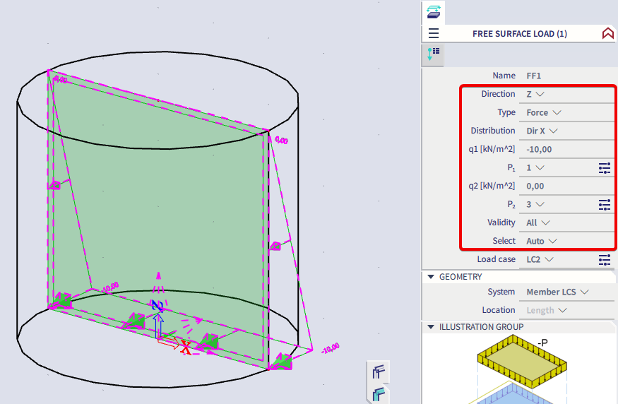
Generating this load gives the following result.