Variable slab thickness
When creating a new 2D member, the property ‘Thickness type’ is by default ‘Constant’ and cannot be changed. Afterwards the ‘Thickness type’ can be put to ‘Variable’ via its properties. At that moment, the input options for the definition of the variable thickness appear: 'Global X', 'Global Y', 'Global Z', 'Local X', 'Local Y', 'Variable in two directions' and 'Variable in 4 pt.'.
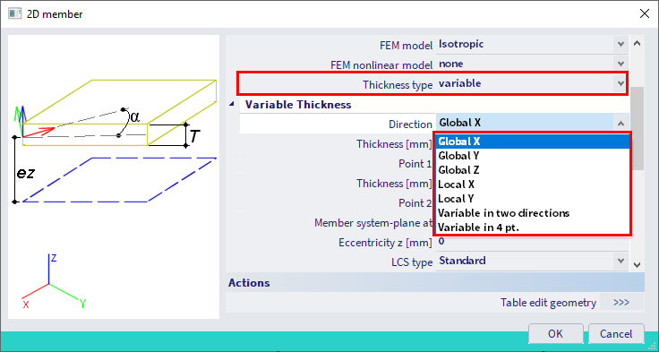
The options Global X / Y / Z allow the thickness to vary in the global X / Y / Z direction, while the options Local X / Y allow a variable thickness in the local x or y direction of the slab. In both cases you have to select two slab vertices (nodes that are part of the slab edge), for which the thickness can then be specified. The thickness is extrapolated automatically to the other member nodes.
Note that the options Local X / Y are only available for plates and straight walls (not input as shells!); the same is valid for Variable in two directions.
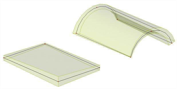
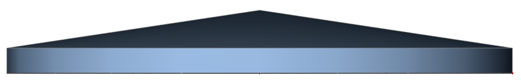
For all 2D members with 4 slab vertices the option Variable in 4 points is available as well. For each of the 4 (principal) edge nodes, you can input the thickness. An example is shown below:
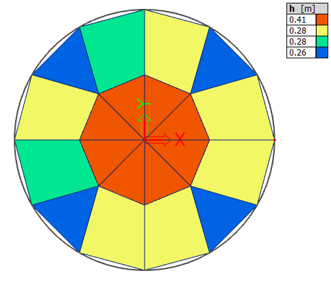
For circular slabs a last option Radial is available, by which you can define the thickness in the centre of the slab and on its edge. Additionally, the eccentricity might be adapted to obtain the following result:
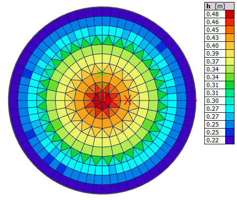
Keep in mind that the finite element mesh size will influence the accuracy of the variable thickness of the member, since each finite element has a constant (averaged) thickness. After the Calculation this can be checked via the Main menu > Results > Thickness of slabs: