Create drawings
With SCIA Engineer you can create different kind of drawings: overview drawings, steel connection drawings,... The drawings can be manipulated further in the Image gallery or Paperspace gallery and can be added to the Engineering report.
Overview drawings
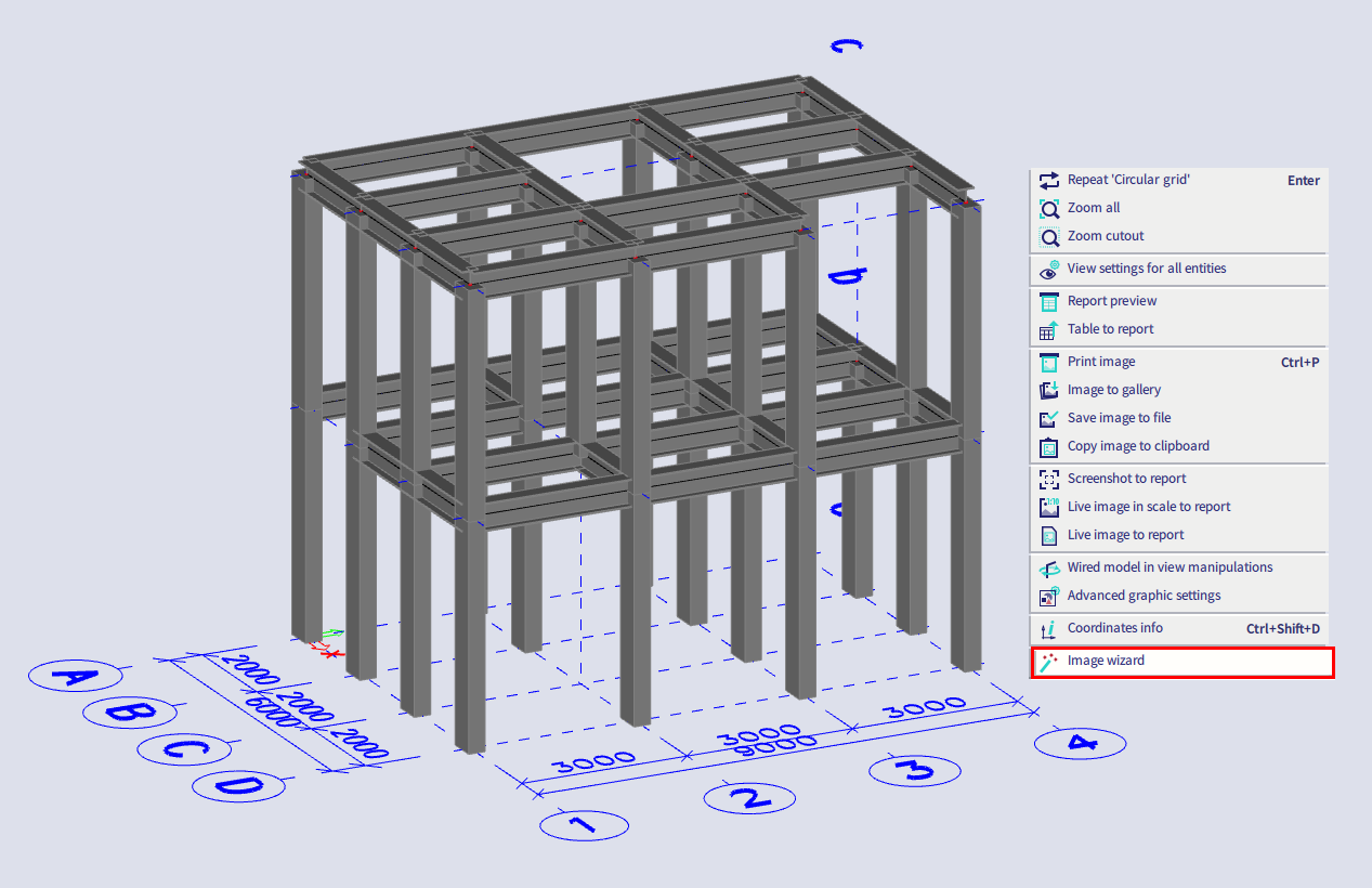
To be able to create overview drawings, a 3D line grid is needed in the model. If a 3D line grid is present in the model, you can create the overview drawings via right-clicking in the graphical scene and choosing Image wizard (or by searching for this command in the SCIA Spotlight).
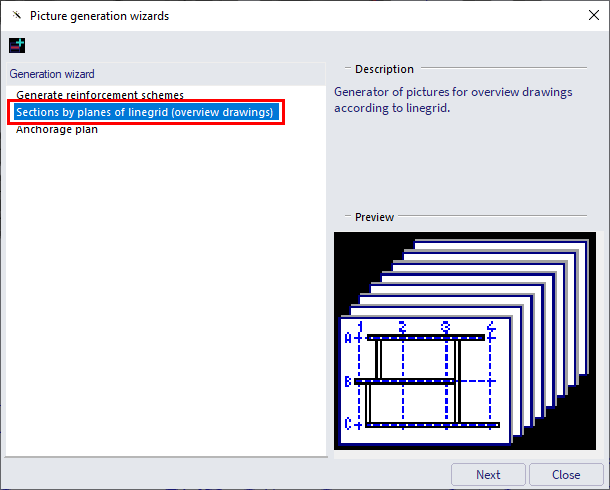
Then select Sections by planes of linegrid (overview drawings) and click on the Next button.
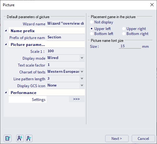
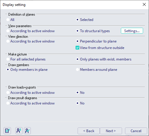
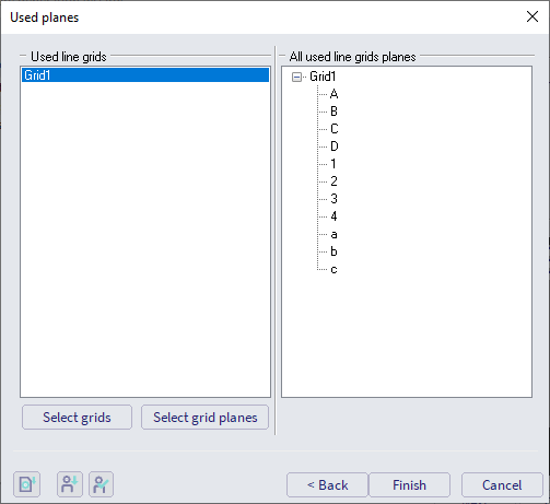
In the next dialogue several general settings can be changed (Scale, Text scale factor,...). In the next dialogue you can change display settings. Here you can choose as well if you like to generate drawings for all planes or if you want to make a selection. Finally in the last dialogue you can select the grid and if you have chosen Selected in the previous dialogue you can select here as well the desired grid planes (if you have chosen All in the previous dialogue, the button Select grid planes will not be available).
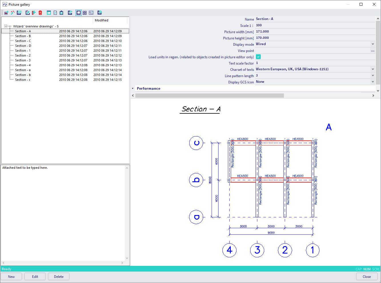
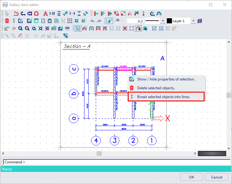
After confirming with Finish, the drawings will be generated. Note that this can take some time for bigger models and if a lot of planes are present. When the drawings are successfully generated, they can be found in the Image gallery (Main menu > Libraries > Image gallery). Now it is possible to edit each drawing. In the editor it's possible to add additional dimensions, lines or text, move labels,... Note that it can help to 'explode' item(s) by selecting them, right-clicking and choosing Break selected objects into lines.
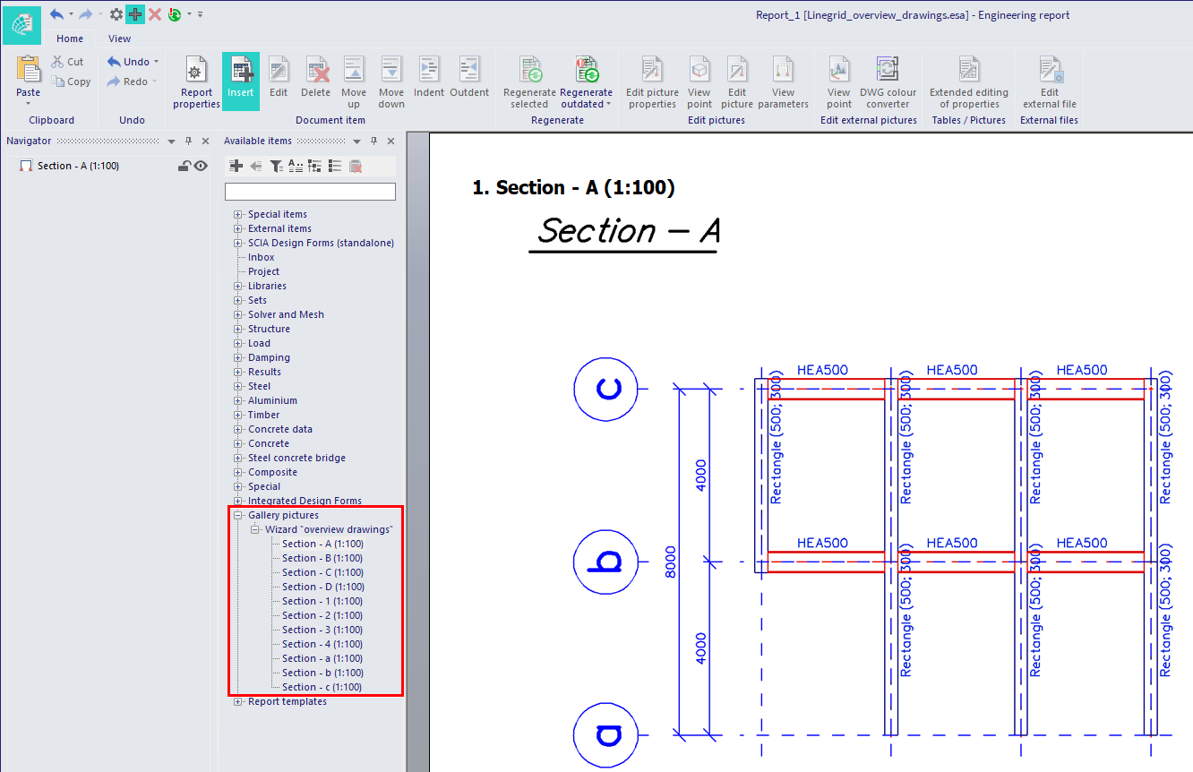
Gallery pictures can be added to the Engineering report
Paperspace gallery
Another gallery is the so-called Paperspace gallery (Main menu > Libraries > Paperspace gallery).
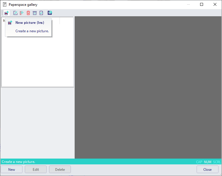
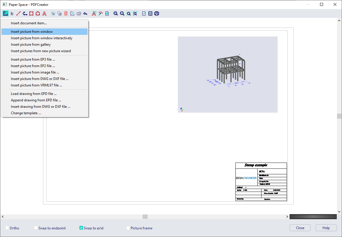
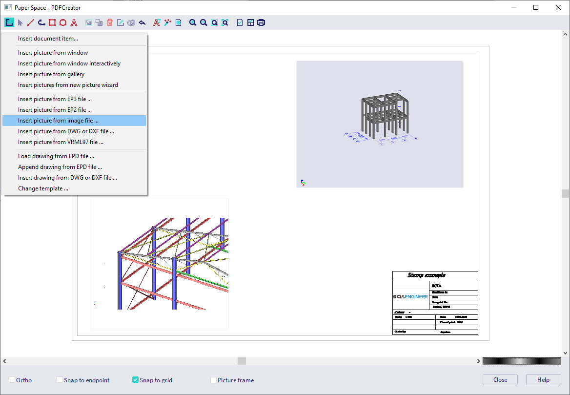
There you can create a plot with multiple drawings. You can add drawings from the graphical scene via Insert picture from window. Or you can insert an image with extension *.bmp, *.jpeg, *.png, ... via Insert picture from image file.
There are settings for the stamp+header and for the page (paper size, margins,...).
Paperspace pictures can directly be printed (to a physical printer or a PDF tool) or can be saved as *.bmp, *.dxf, *.dwg,... file.
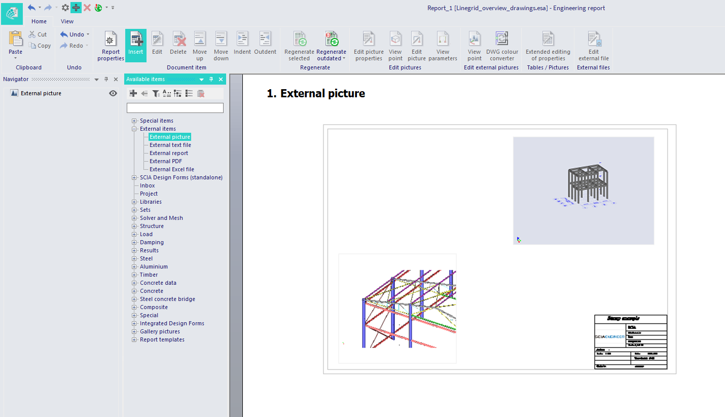
You cannot add paperspace pictures directly to the Engineering report, but you could first create a *.pdf, *.bmp,... file and add this file via the External items (External picture or External PDF).
Steel connections
Similar to the overview drawings the Image wizard can be used to generate drawings for steel connections.

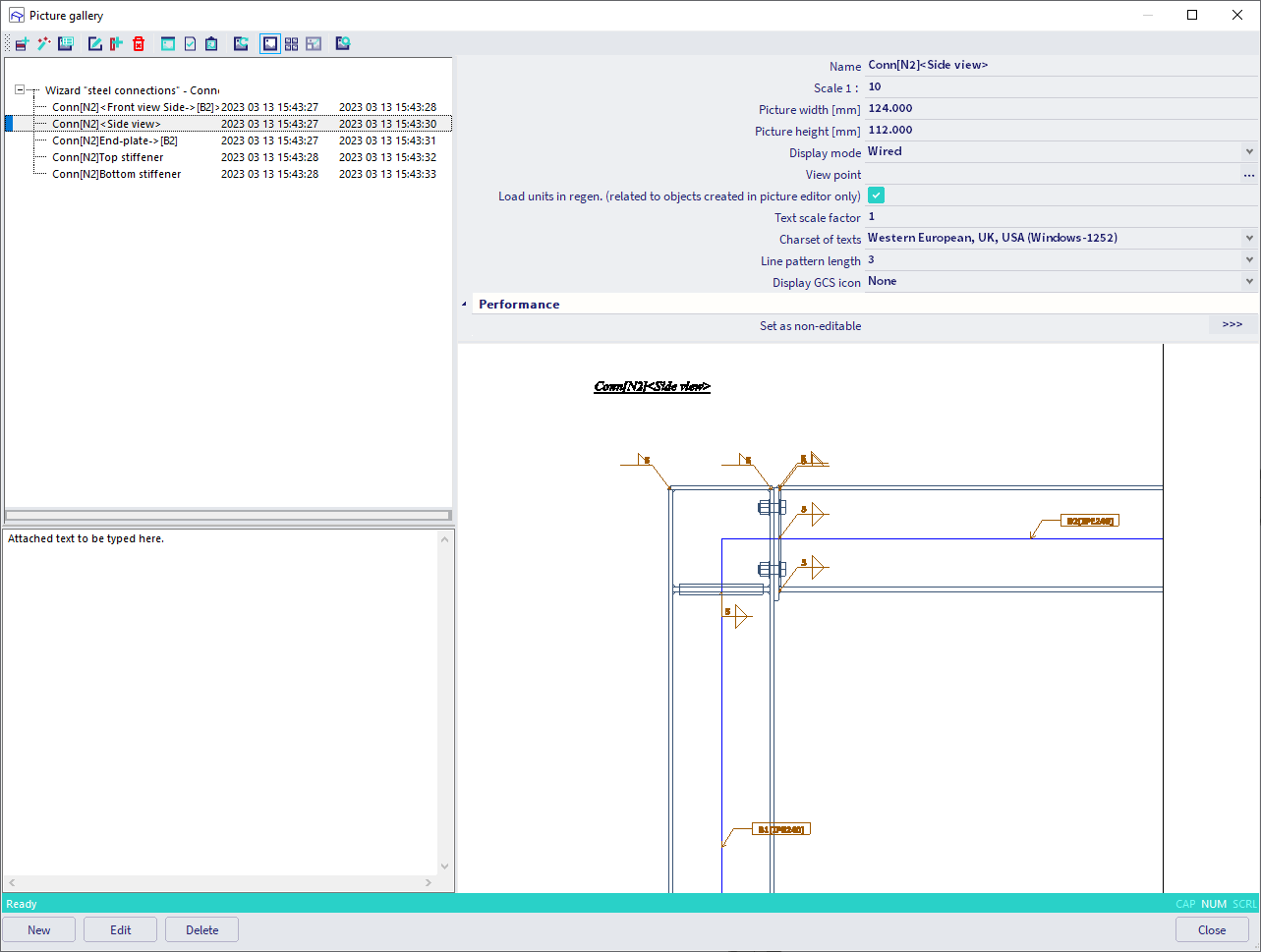
Similar as for the overview drawings, you can set some general settings, display settings and select all connections or make a selection by yourself. Afterwards the drawings can be reviewed in the Image gallery.
Also these drawings can be added directly in the Engineering report.