Steel design
Eurocode steel summary output
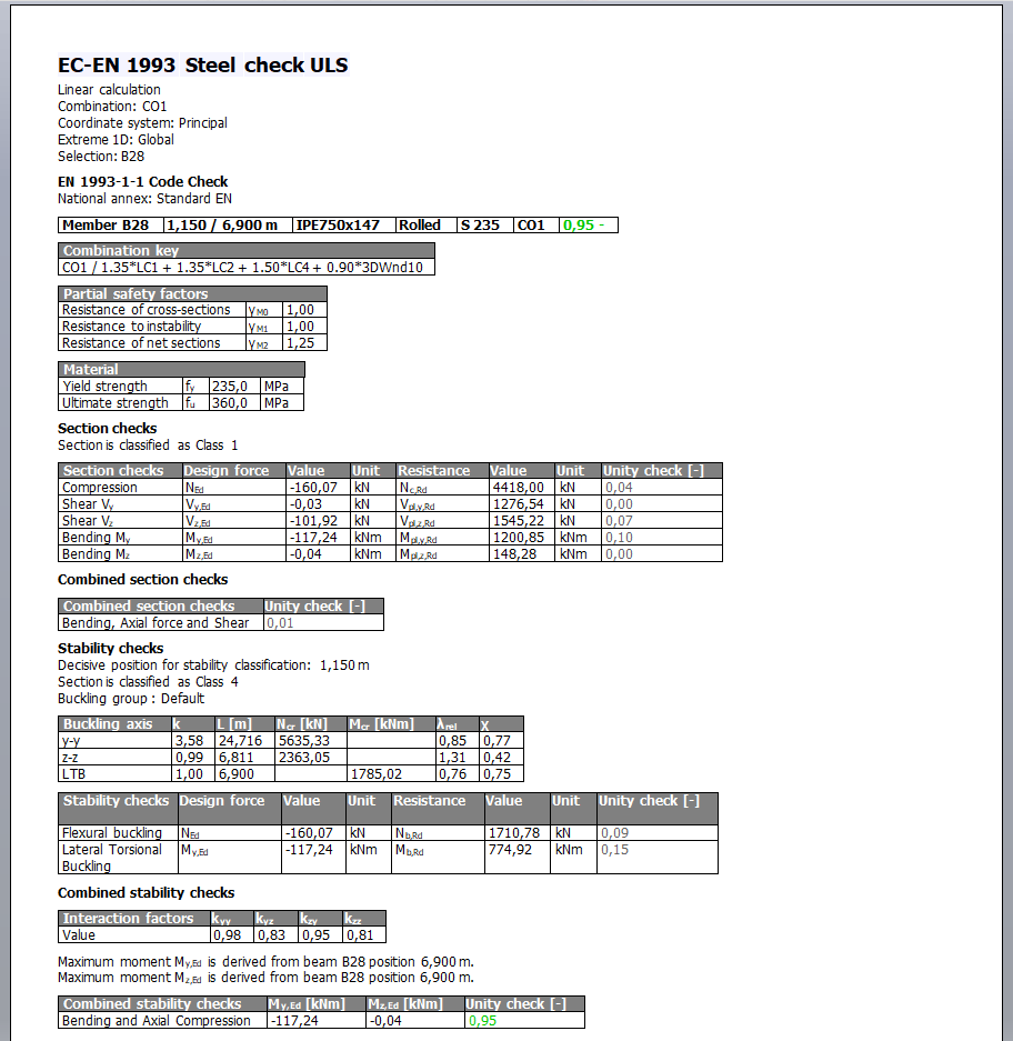
One of the top three voted items in the customer poll for version 22 was to extend the Eurocode steel summary output with more information for control offices. Based on our clients feedback, the following items were added or tuned:
- For every code check, the design force, resistance value and the corresponding unity check are displayed.
- The used internal forces for the combined stability checks and their position on the member are shown together with the interaction factors.
- The material properties and applied safety factors have been added.
- Colour coding has been added to the unity checks to allow for a quick detection of important output values.
- The output always fits into one A4 page.
Shear centre eccentricity
Version 22 of SCIA Engineer comes with a brand-new option to consider the shear centre eccentricity of cross-sections directly during the finite element analysis. In previous versions, it was only possible to consider the effects in post-processing of results or via a manual input of the loads with the desired eccentricity.
Today, it can be simply selected in the Solver Setup, via the new option “Neglect shear centre eccentricity”.
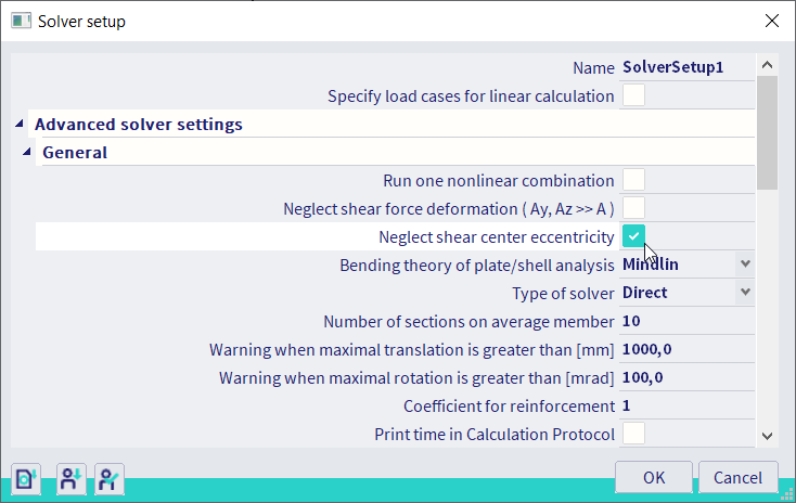
When this option is activated, the shear centre eccentricity is neglected, and the results of the analysis remain like in previous versions. The position of the shear centre is considered the same as the centre of gravity, and therefore loading applied to this centre of gravity will not generate additional torsion – even for asymmetrical profiles.
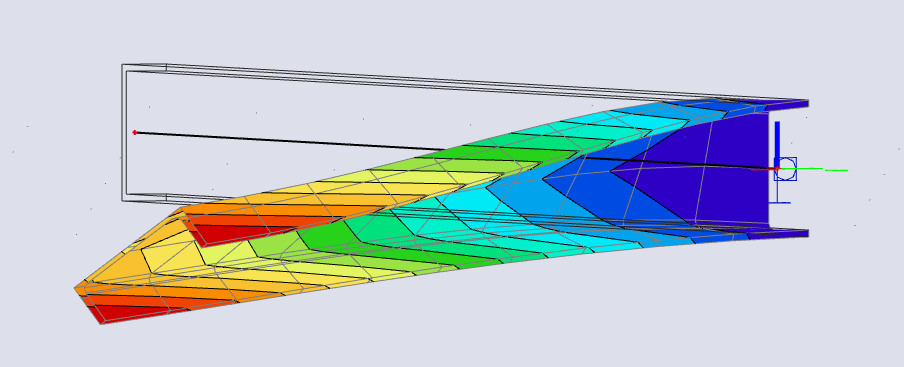
The picture below shows the deformation of a U-profile under self-weight as it was in previous versions, with the shear centre eccentricity neglected.
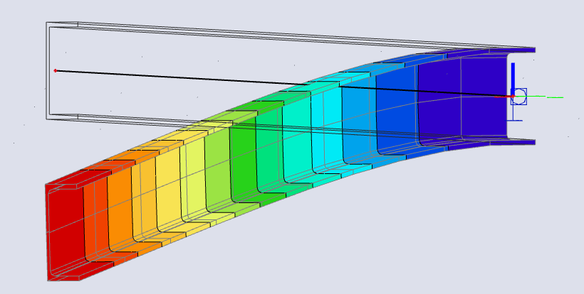
When the option is deactivated – the default option in SCIA Engineer 22 – the position of the shear centre is properly considered in the analysis. Loading in the centre of gravity of a section with a shear centre located outside the centre of gravity will produce torsion effects.
The picture below shows the deformation of a U-profile under self-weight in version 22, with the shear centre eccentricity taken into account.
Starting from version 22, the shear centre eccentricity is be taken into account by default for all new projects.
What is the difference in the results between the previous and new option?
In previous versions, the analysis was unable to account for the position of the shear centre. When displaying the internal forces in the results menu, there was an option to calculate and add the additional torsion from this eccentricity to the displayed forces. However, these additional forces were not considered in displacements, design checks and did not have any effect on the elements they were connected to.
With the new option, the shear centre position is considered directly in the analysis, leading to results that already include the additional effects. This means that the additional effects will also be considered in displacements and material design.
Is it possible to neglect this effect for specific sections?
It is possible to neglect the additional effects for specific cross-sections. This can be achieved by overruling the calculation of the shear position in the cross-section dialogue and changing the coordinates to ‘0:0’ to coincide with the centre of gravity. By doing this, the eccentricity will be neglected for this particular cross-section.
AISC Steel code check in 64bit
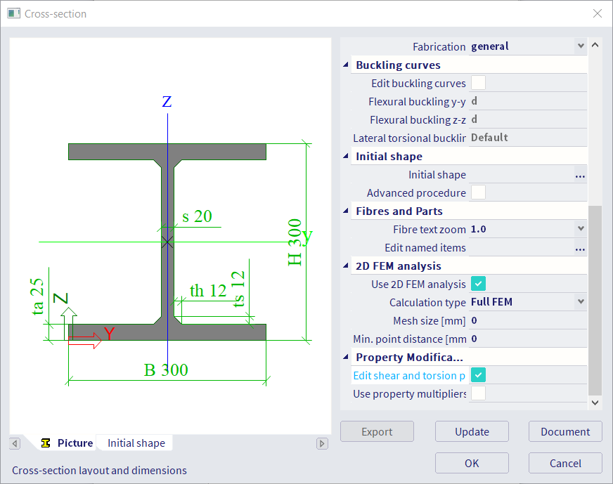
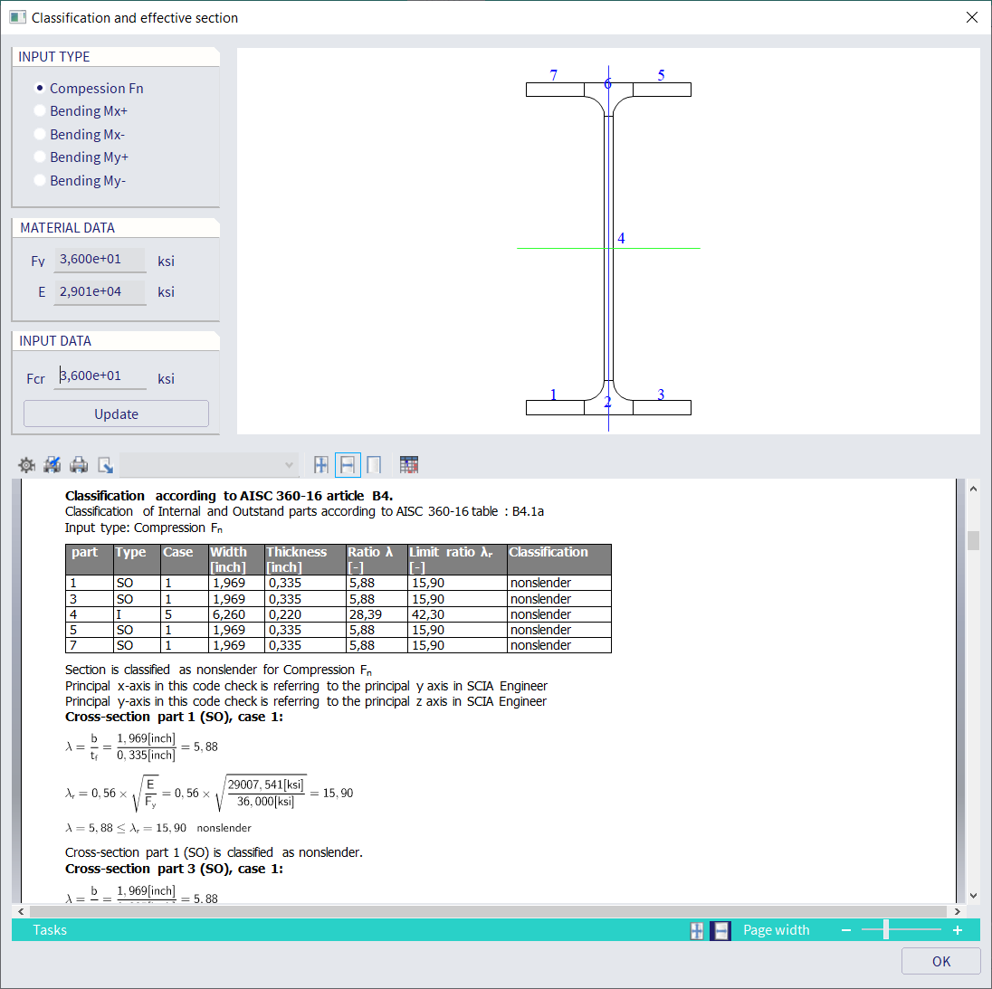
A brand-new implementation of AISC 360: 2016 will is now available in the 64-bit version of SCIA Engineer 22. The changes are apparent even before opening the checks. In the cross-section dialogue, a detailed classification preview is available.
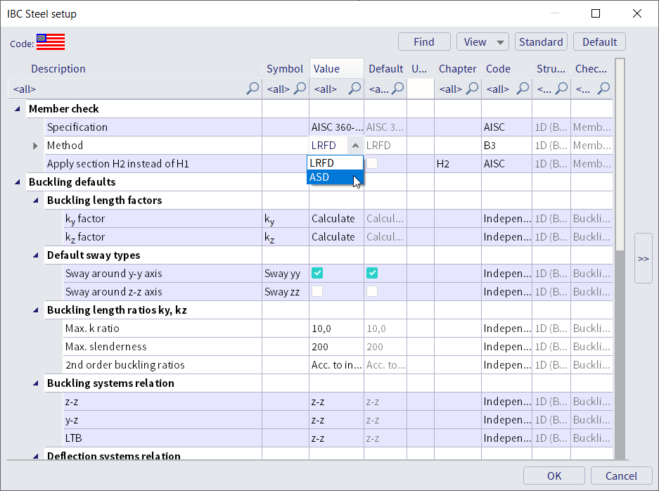
In the completely renewed AISC steel setup, you can select the approach for the check, and you can adjust all the other settings.
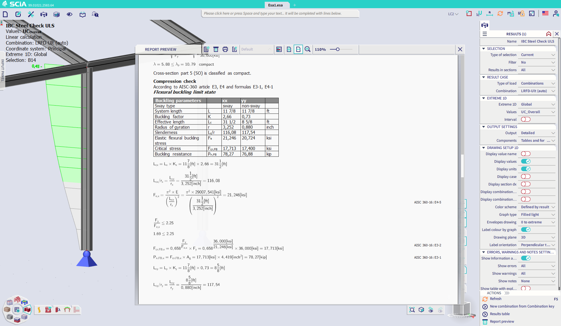
When all the settings are properly set, the code check can be executed. The results can be evaluated in very detail thanks to the new detailed output with formulas. Every applied formula, decision and value can be shown, as well as the references to the appropriate code article.
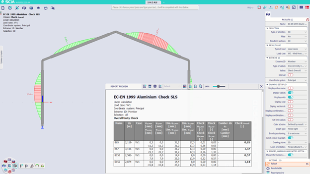
Aluminium SLS design in 64-bit version
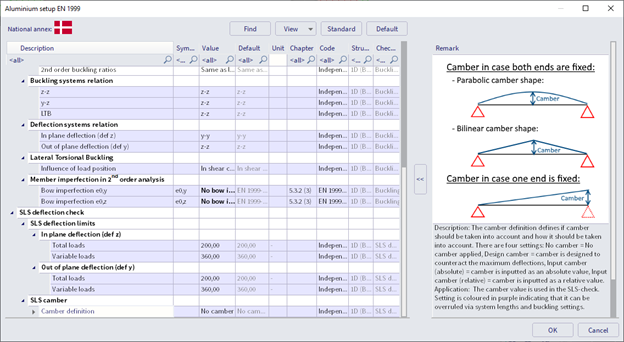
The SLS check for aluminum design has been improved and migrated into the 64-bit version of SCIA Engineer. It now offers the same powerful options as already existed for other materials: limit settings per member, camber design, and separate limits for the variable and total applied loads.
Timber design
Orthotropy for CLT panels
Calculation of stiffness parameters for cross-laminated timber panels is not an easy task, and yet the correct orthotropic stiffness is essential for an accurate calculation of internal forces in the structure.
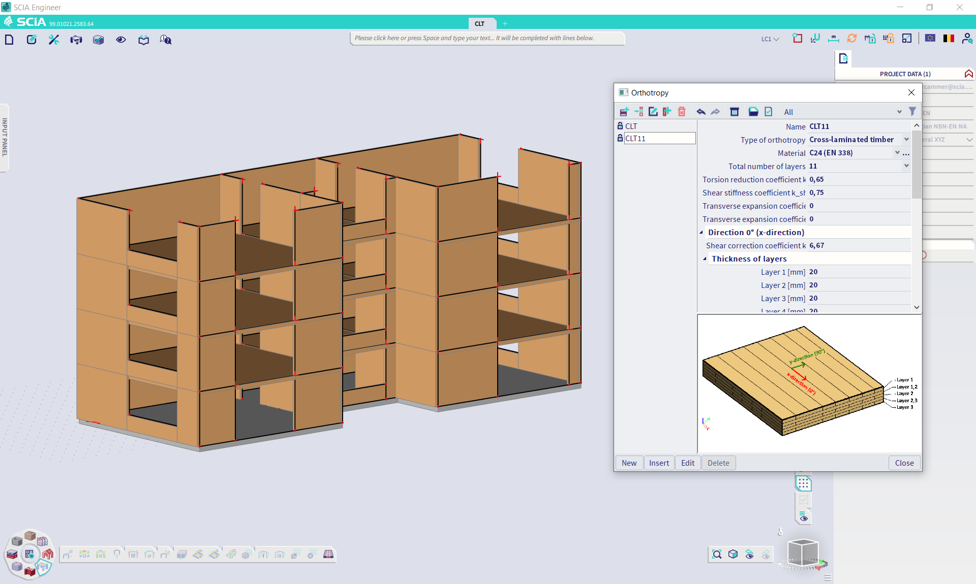
While SCIA Engineer was already capable of considering the orthotropic behaviour for CLT, this procedure has been immensely simplified with the introduction of a new orthotropy type: “Cross laminated timber”. You set your 2D member to an orthotropic behaviour and open the orthotropy menu. There, you can select the new orthotropy type.
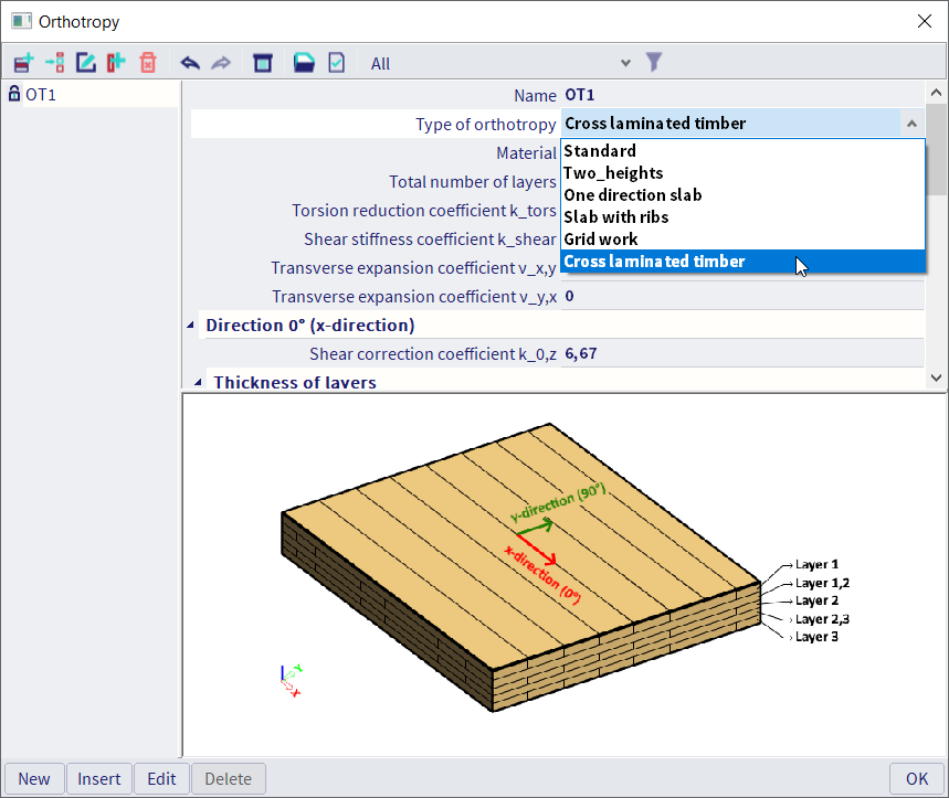
Simply choose your material, number of layers, the layer thicknesses and SCIA Engineer will calculate and apply all the corresponding stiffness parameters to your model. It is the first small step into a comprehensive solution for timber structures.

Want to try SCIA Engineer yourself?
Explore how our software and services can help you optimise your work and boost your productivity. Try it for yourself with a free 30-day software trial.
Download a free 30-days full trial