
Highlighted features

Revolutionary user interface
Save 1 hour per day with less clicks and less mouse miles
- Revolutionary new interface with leading-edge ergonomics.
- Easily customised to suit the way YOU work.
- Less mouse clicks on almost every task.
- A total workspace transformation providing you with nearly 100% screen use.
- Bring the tools you use most to the front, hide the ones you do not - it’s your workspace now.

Intuitive 3D CAD-like modelling
Model even complex geometries with ease and confidence
- Fast and intuitive modelling of straight as well as curved members
- Grids and templates for faster input
- Visual control over all input data
- Optional clear tables to look into details or exchange model with MS Excel
- Import geometry from commonly used formats (IFC, DWG, SAF, ...) and only finalise the model in SCIA Engineer

Multi-material design
Combine multiple materials in one model
- Handle all materials in the same way in one unified user environment.
- Get safe, economical and clearly documented design for any material:
- reinforced concrete (incl. fibre-concrete), prestressed concrete
- steel (incl. cold-formed sections and scaffolding)
- steel-concrete composite floors and columns
- aluminium, timber

Safe and economical design
Deliver safe and economical design every time
- Eurocodes including national annexes and research-based recommendations (e.g. SEMI-COMP+)
- International codes like IBC, NBR, SIA.
- Clear and transparent documentation of all calculation steps
- AutoDesign for optimal sizing and maximum material savings

Engineering Report
Save time on project documentation
- Tables, images, formulas - all in one automated report
- ChapterMaker for fast generation of report sections for all/selected members, load cases, etc.
- Customisable level of detail from one-page summary to comprehensive report with all code references, intermediate steps, etc.
- One-click report update after any last-minute changes to the model
What's new in version 25.0

Vibration analysis
- Steady-state harmonic analysis for a single frequency or a range of frequencies
- Nodal, line and surface harmonic loads
- In-phase and out-of-phase harmonic loads
- Rayleigh and constant damping
- Peak and RMS values for accelerations, velocities and displacements
- Load sign assigned automatically based on the selected modal shape

Design and check in construction stages
- Ability to perform check of structural elements in individual construction stages
- Check for reinforced and prestressed concrete and steel
- Streamlined workflow in the design of multistorey buildings

Stability analysis in construction stages
- New enhancement in construction stages analysis
- Improved workflow in the design of multistorey buildings
- Ability to run a stability analysis for individual phase of construction

3D wind load generator
- Improved handling of corner zones and canopy roofs
- Wind pressure and wind friction effects
- Closed, open and canopy structures can be analysed for the resistance to wind loads
- Libraries of terrain category, zone, roof type, basic wind velocity, etc. are available
- In compliance with EN 1991-1-4:2005 and ASCE 7-05
- Pressure coefficients are editable to take into account geometrical and other conditions not represented in the analytical model

Convergence graph for nonlinear analysis
- Graphical visualization of the convergence progress in the nonlinear analysis
- Possibility to export the data to an Excel spreadsheet
- Graphs available both during and after calculation

Bridge combinations improvement
- Ability to introduce thermal load
- Uniform and gradient loads available
- In compliance with EN 1991-1-5
- Optional modification of applied coefficients in the national annex set-up

Update of AISC and ASCE code
- Update to the latest rules described in ASCE 7-22
- Checks performed according to the latest AISC 360-22 rules
- Automatic update of older projects

Update of the American and Brazilian profile libraries
- Update of American profile libraries
- Update of Brazilian profile libraries
- Introduction of new configurations for L-pair sections

Link with FRILO B5+
- Component-oriented design of a reference column from SCIA Engineer with the B5+ reinforced concrete column programme from FRILO
- Automatic transfer of all relevant data such as geometry, material, load
- Calculation mode: design, verification and ultimate load
- ULS and SLS design check
- high strengthen steel, fire design
Modelling & loading
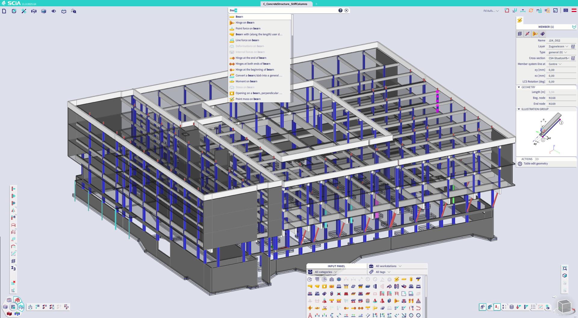
Revolutionary new interface
SCIA Engineer’s revolutionary new interface works in perfect harmony with the structural engineer: Less mouse clicks on almost every task. A total workspace transformation providing you with maximum screen use, with the project taking the centre stage. And with SCIA Spotlight you instantly find the tools and functions you need.
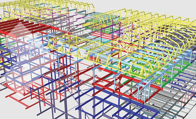
BIM-like modelling
SCIA Engineer provides an intuitive way to work with structural objects. Unlike traditional software tools where you need to work with individual nodes and finite elements, SCIA Engineer allows you to define members with just one click or sketch complex curved shells just as easily as in today's CAD and BIM authoring tools.
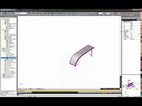
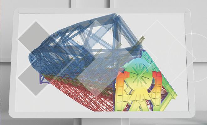
Curved shapes
Curved beams and shells with constant or variable thickness, can all be easily defined through the modification of simple properties. Additionally, intersections between surfaces can be automatically generated and used as a basis to create cut-outs. This makes it easy to model complex geometry compared to more traditional finite element design tools.
Grids & stories
To facilitate the modelling of buildings and frames, SCIA Engineer comes with a wide range of 2D and 3D Grids: Cartesian, Oblique, Cylindrical, Spherical, Arbitrary (Free) grid lines
Any number of grids can be used in the project, activated or deactivated, and freely rotated.
In the case of multi-story buildings, Stories will enable you to better navigate your model, quickly switch from one floor to another and to visualize results per floor.
Powerful filtering & selection tools
All structural objects and additional data can be easily accessed via a number of filtering and selection tools, removing the dependancy on navigation within the 3D environment:
- By selecting a single item, one can easily filter all other items in the model that share a similar property.
- Work with just a portion of a project active on screen. This filtering can be done based on layers in the model, on proximity to workplanes, on clipping boxes, etc.
- Selected elements can be saved, edited and reused at another time.

Table input
When modelling a project in a 3D atmosphere may not be the most efficient, the table input can be used as a straight forward way to create geometry. Some of the features included in the table input are:
- Input for most of SCIA Engineer’s structural elements, loads and libraries
- Import large data sets or functions from Excel
- Link between table input and graphical window, so individual selections are easily identified
- Support for parametric input and keyboard shortcuts
Parametric modelling
Parametric modelling allows users to actively adapt the model in order to quickly create design iterations of either repetitive or complex structures. Parametric models are generated by establishing parameters, which can include any model element or property (coordinates, dimensions, cross-sections, materials, loads, etc.).
Finally, parametric templates can be established in order to allow users to create or modify projects by utilizing predefined objects, thus creating great efficiency in the modelling process.

3D wind generator
SCIA Engineer will automatically generate and apply 3-dimensional wind loads to your entire structure according to the provisions found in the Eurocode 1 and ASCE 7-05/7-10. For the ASCE, both the Directional (All Heights) and Envelope (Low Rise) methods are supported for automatic generation of load cases (including torsional cases) on enclosed and partially enclosed structures.
Furthermore, SCIA Engineer’s graphical interface allows users to easily review and verify the pressure coefficients and surface loads being applied to various locations of the structure.

Free loads
Free loading allows users to create loads which are defined independently of the structure geometry or meshing, creating flexibility in a variety of load applications.
The range of uses for free loads includes: equipment load on slabs that will be perfectly mapped to the underlying mesh, hydrostatic loads on complex shells and user defined wind pressure.
Straightforward Load Application
SCIA Engineer lets you model all standard load types: concentrated and distributed forces, moments, support settlements and thermal loads visually as objects. These load objects can then be moved or copied to other members or other load cases while also easily being filtered and modified through the property window just like any other data in SCIA Engineer.
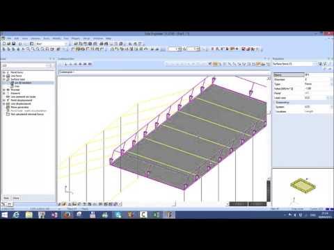
Practical load panels
Load Panels in SCIA Engineer are used for the specific task of distributing applied loads to the structural elements of the model. In most applications, load panels represent façades or other non-bearing structural elements. SCIA Engineer utilizes these elements to distribute load using 1-way or 2-way action before analysis, allowing for a reduction in model size, improvement in calculation speed and an increased transparency in applied loads and results.
Furthermore, SCIA Engineer’s graphical interface allows users to review and modify the generated loads being applied to various locations of the structure.
Analysis & results
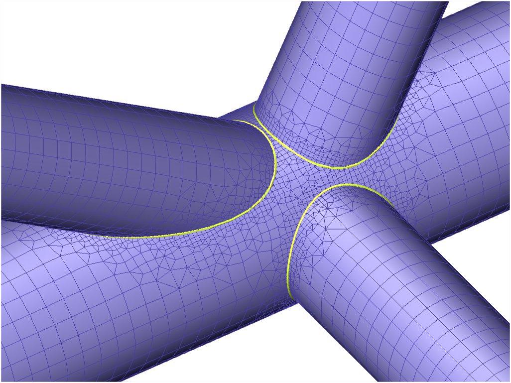
Meshing with automatic refinements
SCIA Engineer’s meshing will make sure that the transitions between complex surfaces or various mesh sizes is always smooth, guaranteeing quality results from the finite element analysis.
- Automatic generation of finite element mesh, based on user defined global mesh settings that is consistent and error-free.
- Local mesh refinements at specific locations including; around nodes, along lines or edges and on an entire surface
- Automatic Mesh Refinement for optimal mesh and and feedback on the quality of current mesh
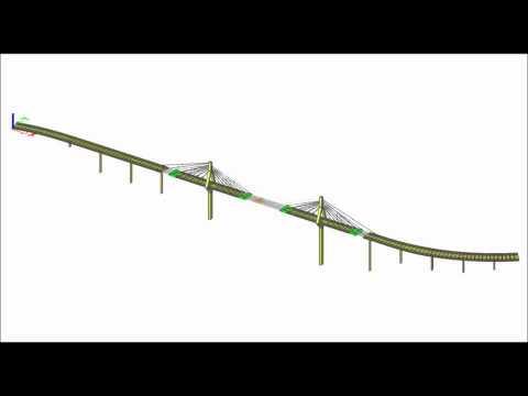
Dynamics
In addition to standard eigenmode analysis to determine the eigen frequencies and mode shapes, SCIA Engineer allows you to run all standard types of dynamic analysis and then some: earthquake analysis through modal superposition, harmonic (sinus) loads, Von Karman wind on tubes and full time-history analysis with definition of time functions for loading.
Additionally, the Improved Reduced System (IRS) method vastly reduces the number of eigenmodes that need to be considered for an earthquake analysis, thereby eliminating local modes and increasing the overall speed and accuracy of the calculation.
Construction stages
Construction stages in SCIA Engineer allow users to understand the time dependant behavior of a structure:
- Progressive construction of cross-sections.
- Gradual application of loads and prestressing.
- Changes of boundary conditions.
- Removal of temporary structural elements.
- Use of deformed shape from previous stage using nonlinear functionality.

Large displacements
2nd & 3rd order analysis executed on any structure type. These analyses take into account deformations of the structure (P-δ and P-Δ effects) with or without imperfections assigned to members.
- Various iteration methods (Timoshenko, Newton-Raphson, Picard) and boundary conditions (tension only, initial stress, limit force and gap)
- Ability to utilize Direct Analysis Method or equivalent notional loads through use of global and local imperfections
- True cable analysis with ability to define as straight or slack (including definition of either self-weight or other load used to define cable slack)

Material non-linearities
- Various types of material non-linearities can be included in the analysis:
- Input of nonlinear hinges and springs by the defining of functions, both on linear elements and on surfaces (edge hinges)
- Nonlinear material behaviour (plasticity) can be employed through the use of plastic hinges on 1D members or by using general material plasticity for 2D members
- Concrete non-linearity can be considered through a physical non-linear analysis taking into account redistribution due to precise behaviour laws of concrete and reinforcement.
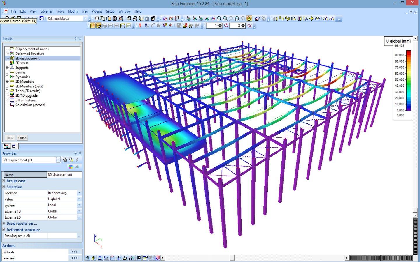
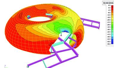
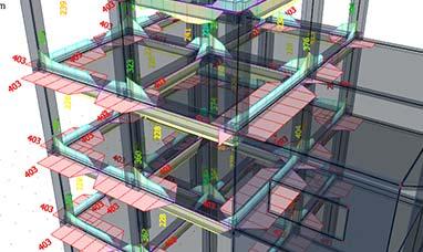
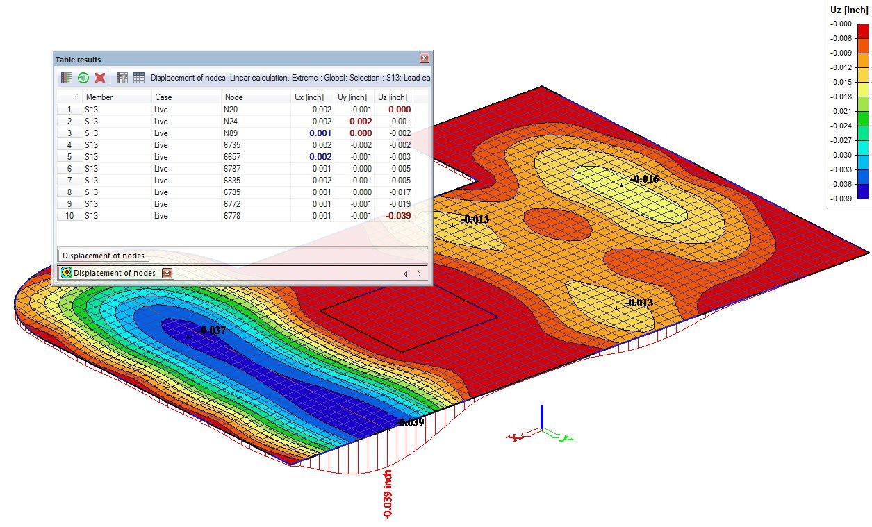
3D displacements & stresses
Deformations and stresses play a vital role in determining whether or not a structure was modelled properly and behaves as expected. As a result, SCIA Engineer provides extremely precise visualization of these results, on the initial or the deformed shape, displaying results on each fibre of a 1D cross section and on both faces of a surface - thereby giving the user an in depth look into the performance of the structure.
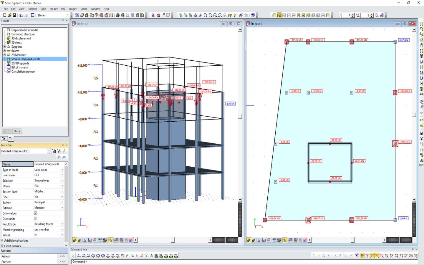
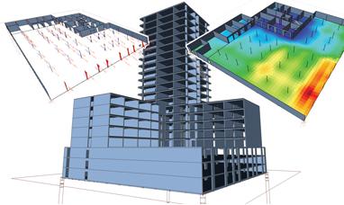
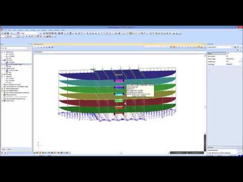
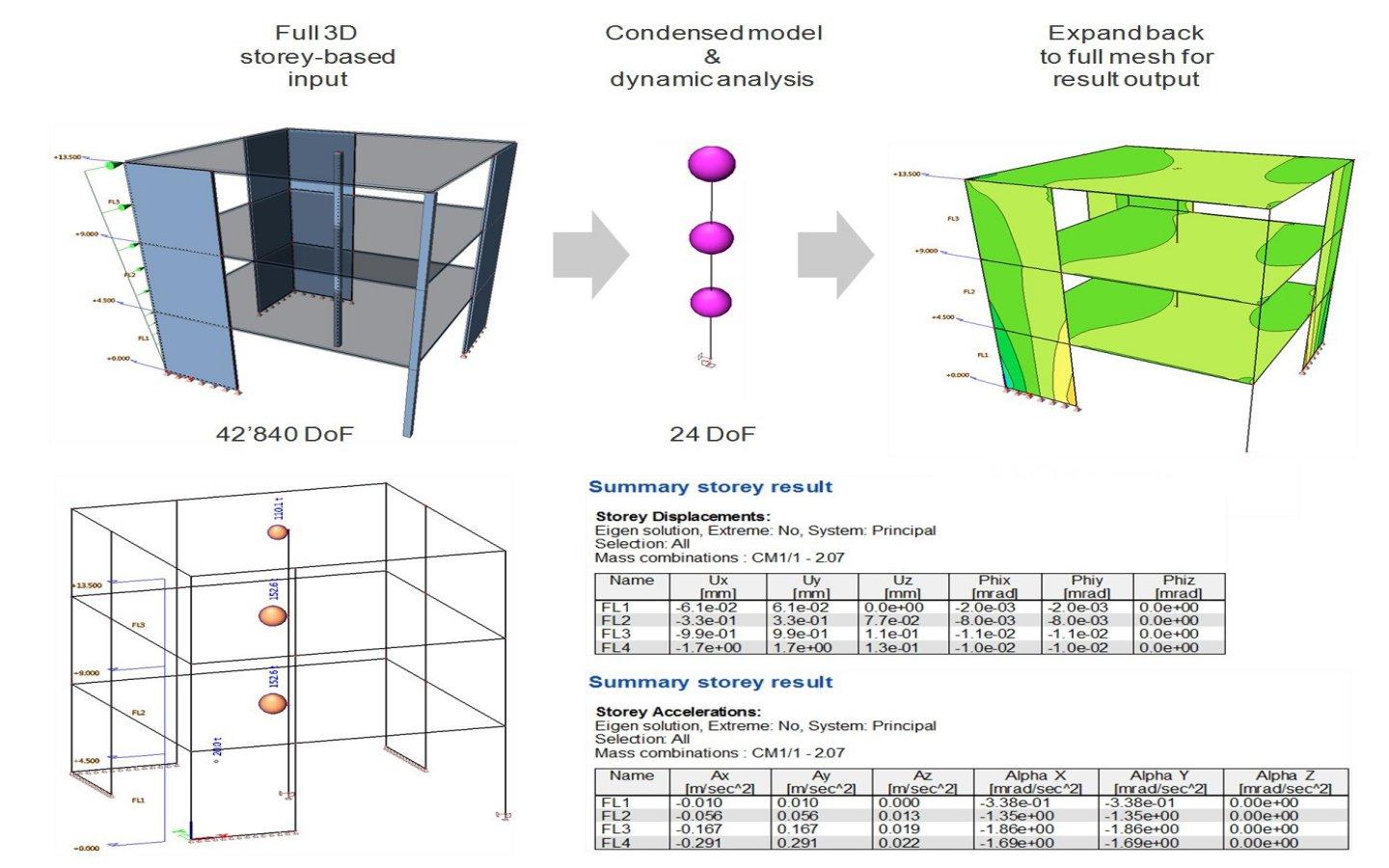
Storey results
After running a lateral load analysis (wind, earthquake, etc) results can be summarized per storey to include:
- Summary storey results: center of mass, displacements, accelerations, interstorey drift, storey forces
- Detailed storey results: internal and resultant forces on individual load bearing elements (columns and walls)
Flexible graphical results
Since there is not a standard way to display results that is optimal for all situations, SCIA Engineer gives users unmatched flexibility in the display of results. In specific, users can utilize results with: different types of colouring, flexible diagrams, filtering/selection tools and adaptable text labels/fonts in order display output that is unique to the needs of the project.

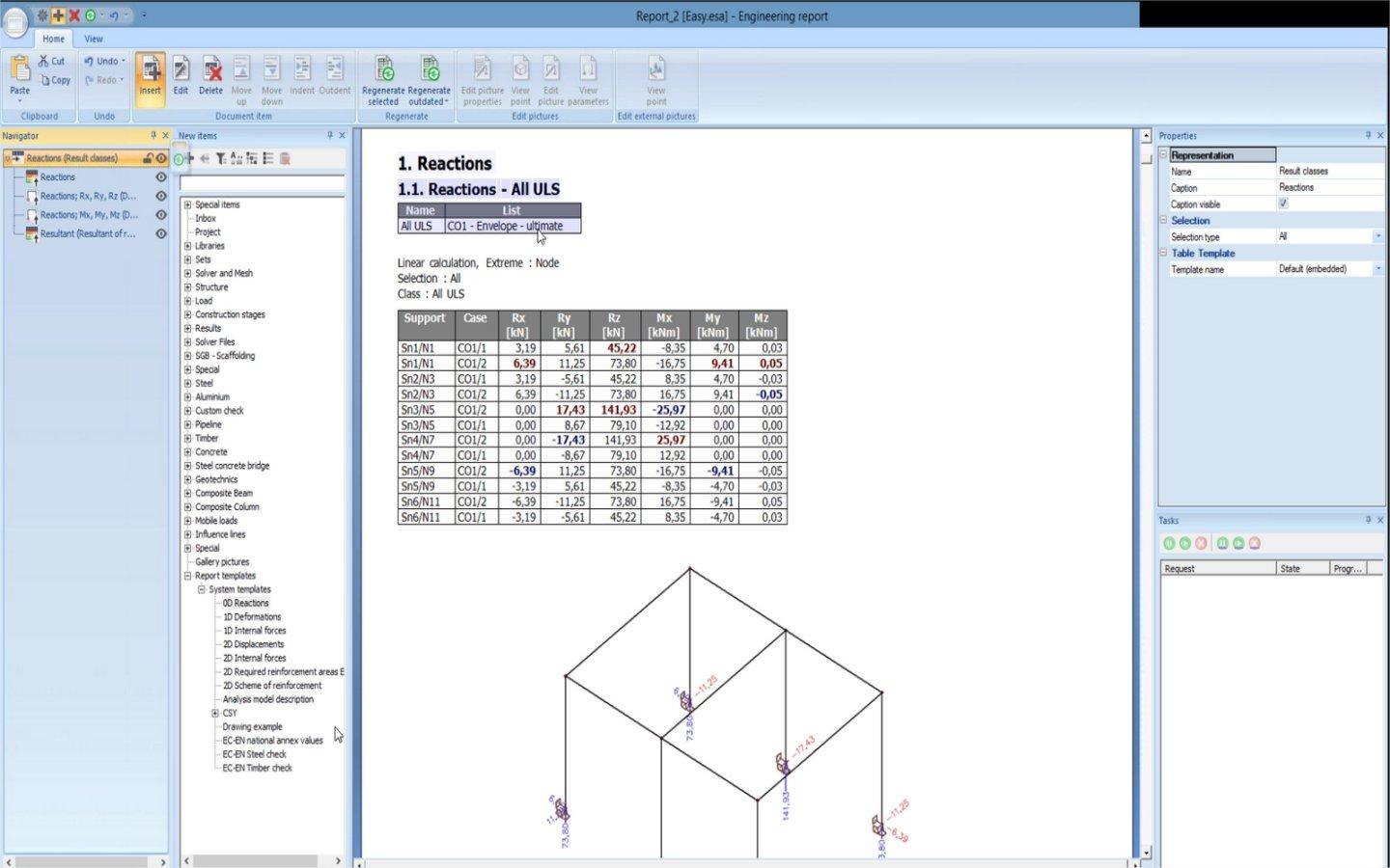
Results tables
The ability to visualize output graphically is incredibly beneficial but sometimes, engineers need to review data in table format as well. In SCIA Engineer, all result types can be viewed in a powerful table results tool complete with:
- Customizable columns
- Sorting and filtering of table values
- In-cell colour bars that give visual feedback on where min and max values are located
- Support for direct selection and copy-paste to Excel
Design & reporting
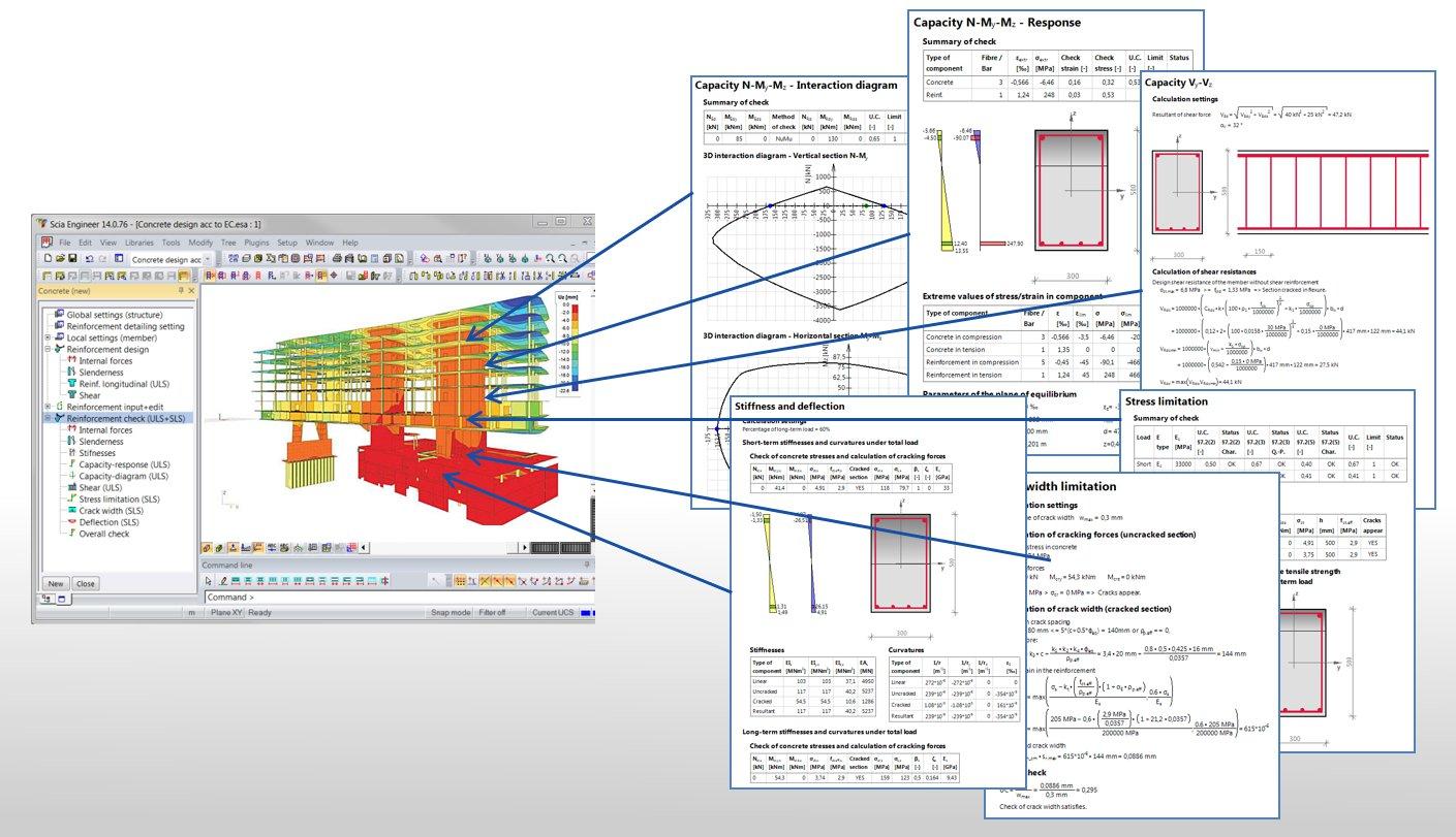
Transparent reinforced concrete design
Concrete member design in SCIA Engineer combines the best of an integrated FEA solution and straightforward hand calculations in order to offer a high level of productivity without the need to worry about transferring data to other external software.
- Transparent: all code formulas are available in the report, showing original mathematical notation, intermediate numerical values and final results
- Complete: all cross-section shapes and internal force situations are supported; including normal force, bi-axial bending, bi-axial shear and torsion
- Fast: supporting all available cores for parallel processing

Structural steel design
Perform section design of steel members according to EN1993 and other international codes. Autodesign of a wide range of profile library cross-sections as well as built-up or arbitrary profiles.
All necessary effects are also considered: section resistance to normal forces, bending, shear, buckling, torsional buckling, lateral-torsional buckling, local buckling, etc. Additionally, buckling lengths are automatically determined and can be reviewed graphically and numerically. The second order analysis (required by Eurocodes in specified situations) can be also performed.

Composite beam design
- Manufacturer libraries for steel studs and decking
- Design and optimization of steel profiles and studs per Eurocode 4 and AISC 360-10 (LRFD & ASD)
- Detailing checks for concrete slab, steel deck and studs
- Serviceability checks (with respect to camber) for both construction and composite stages
- Fully transparent output with rendered formulas and all calculation steps

Steel connections
SCIA Engineer provides users the unique ability to model steel connections within the 3D model. Connections can be defined as either rigid, pinned or diagonal with various plates, bolts, stiffeners, haunches and welds defined. Once a connection is fully modeled, its stiffness can be determined and then used as a hinge type in the larger building model. Additionally, with the implementation of SCIA Design Forms, users can apply specific connection types to FEA nodes in order to execute a full limit state design with dynamic graphics and fully transparent output.
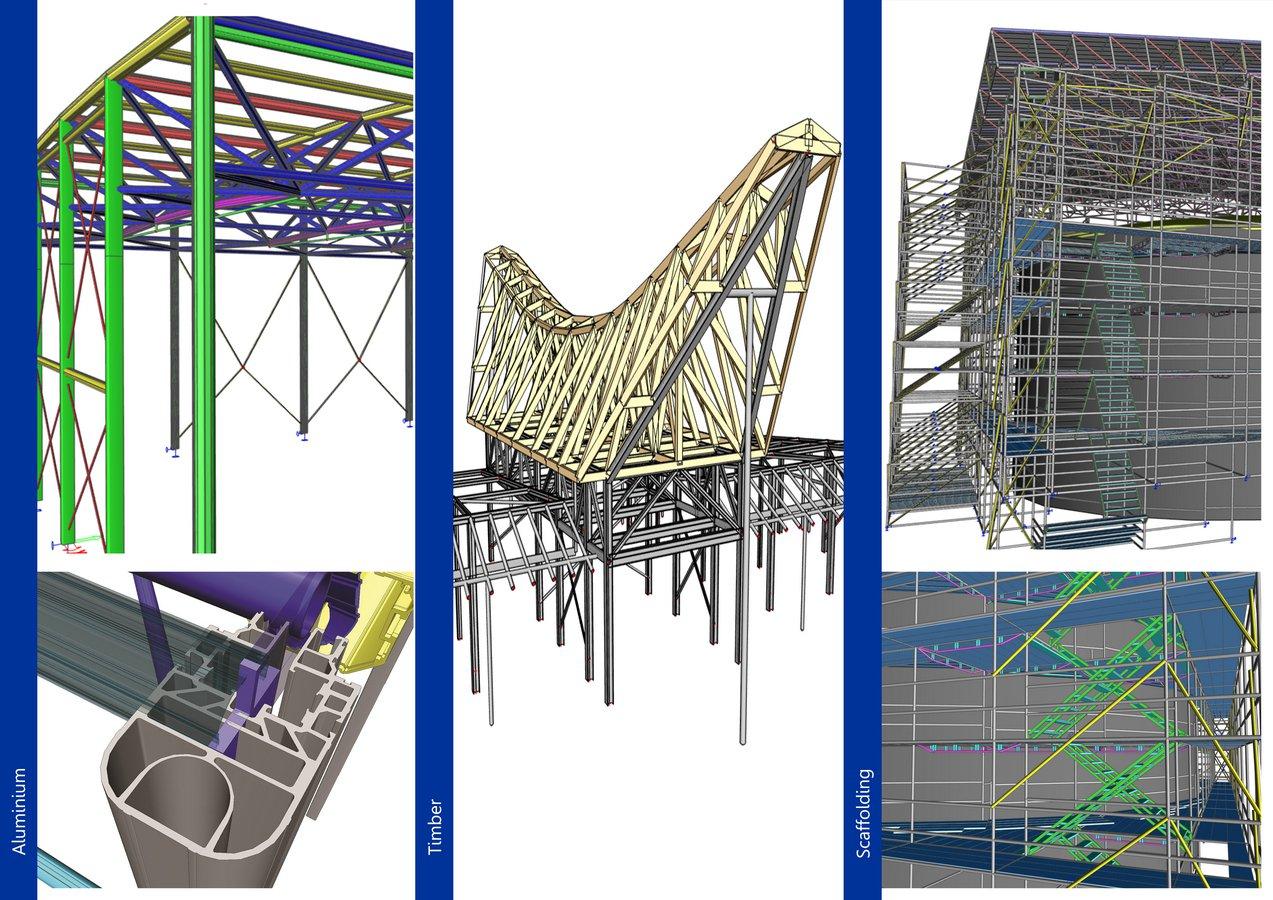
Timber, aluminium and scaffolding
- Timber (EN1995): section and stability checks of timber beams. Includes special checks for creep, variable height and curved elements.
- Aluminium (EN1999): standard and custom aluminium profiles can be defined and checked. Includes calculation of effective properties, influence of heat affected zone.
- Scaffolding checks according to EN 12810 and EN 12811: tube & fittings or system scaffolds are fully supported.
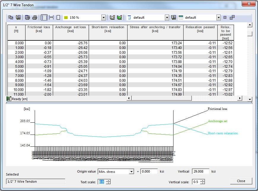
Prestressed concrete
Fully integrated solution for modelling, analysing, designing and reporting prestressed and post-tensioned 1D and 2D members. SCIA Engineer allows users to complete both linear and time dependent analysis in order to accurately achieve results over the life of the structure. Additionally, design checks according to EN 1992-1-1 & EN 1992-2 are included.

Cold-formed Steel
- Derivation of effective shape for arbitrary members, taking into account local buckling and distortional buckling of internal and edge stiffeners.
- Overall design includes allowances for shift of neutral axis, use of average yield strength and steel core thickness.
- Advanced design verifications include web crippling and shear under local transverse forces, also in the case of sections with stiffened webs
- Specialized purlin design includes the derivation of free flange geometry, advanced loading determination, etc.
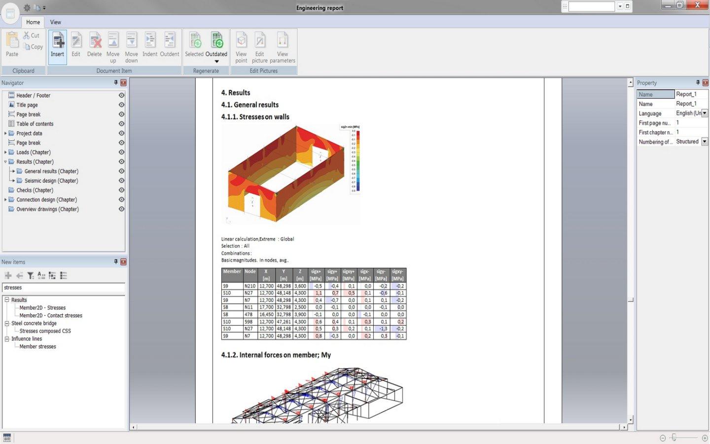
Engineering Report
The Engineering Report is an integrated documentation platform that allows users to create detailed calculation reports with table of contents, model input, loading, analysis and design results as well as model views and graphics. Items added to the report are available in the navigator, allowing for simple user modification. Additionally, since the report is dynamically linked to the model, all items will regenerate automatically to reflect recent changes.
Report Templates
Templates allow users to save custom report layouts (including all results and graphics settings) in order to accelerate the creation of everyday reports.
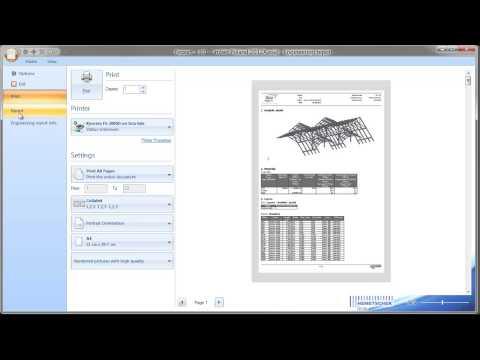
(3D) PDF Support
Exporting from the Engineering Report to Word, Excel or PDF (including 3D PDF) makes finalizing and sharing reports straightforward.
General Arrangement Drawings
- Automatic creation of plan and section views of the structure according to predefined building stories and line grid planes.
- Views and sections can be added to customizable layout pages which can include labels, dimensions, additional graphical model views and table results.
- All drawings are directly linked to the model and therefore will automatically update after any model modifications.
- Export to PDF or other image based file types, while also being saved as DWG, DXF or VRML files.
BIM & collaboration
SAF / STRUCTURAL ANALYSIS FORMAT
SAF is a neutral, MS Excel-based, file format. It improves collaboration between structural engineers and allows them to easily exchange analysis models between different analysis software. It is practical, simple, and intended to be used in daily practice. Originally a Nemetschek Group initiative, the SAF open format has already been implemented or is in progress by many software providers like: SCIA, Graphisoft, Allplan, RISA, FRILO, Axis VM, Dlubal, Sofistik, IDEA StatiCa and more.

SDS2 Interoperability
SCIA Engineer and SDS2 enable a bi-directional workflow connecting structural analysis and steel detailing via the SAF format. Engineers model and analyze in SCIA, then transfer the optimized design to SDS2 for automated, Eurocode-compliant connection design and detailing. Updates in SCIA, like size changes or bracing, sync back to SDS2—speeding up project delivery and improving accuracy from analysis to fabrication.
IFC 2x3 and IFC 4 support
As a co-founder of the OpenBIM Program, SCIA Engineer was the first structural analysis software to implement import and export support for the IFC 2x3 format. It is now possible to exchange data utilizing IFC (Industry Foundation Class) files with over 150 different BIM tools, making the OpenBIM workflow the most robust and flexible interoperability solution on the market.

IDEA StatiCa link
The link between SCIA Engineer and IDEA StatiCa allows for design and code-checks of steel connections and also for checks of whole steel members in IDEA StatiCa applications.
- All required data are automatically synchronised via IDEA StatiCa Checkbot: geometry, cross-sections, materials, members, loads
- Any changes made later in SCIA Engineer are easily synchronised and the IDEA StatiCa project is automatically updated
- Exchange of data using SAF format

Revit link
The link between Revit and SCIA Engineer allows you to start a project in either software with all changes made in one software easily updated in the other one.
- All types of geometry and materials: slabs, floors, walls, shells, beams, columns and bracing in a variety of materials
- Analytical elements: supports, hinges, loads and load combinations.
- Results back into Revit: Deflections, stresses and beam end reactions.
- All changes are tracked and highlighted so you can easily see the edits coming in from the other program.
TEKLA Interoperability
SCIA and Tekla are both part of buildingSMART alliance’s OpenBIM initiative and promote IFC as the preferable format for data exchange of 3D structural models. In addition SCIA Engineer offers a bi-directional link that makes it easy exchange of steel models.
Steel structures and components can be easily modelled in SCIA Engineer, analyzed and optimized, then sent to Tekla for final documentation and detailing. Reversely, models created in Tekla can be pushed to SCIA where the design can be optimized and then pushed back to Tekla for final documentation.
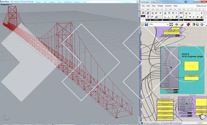
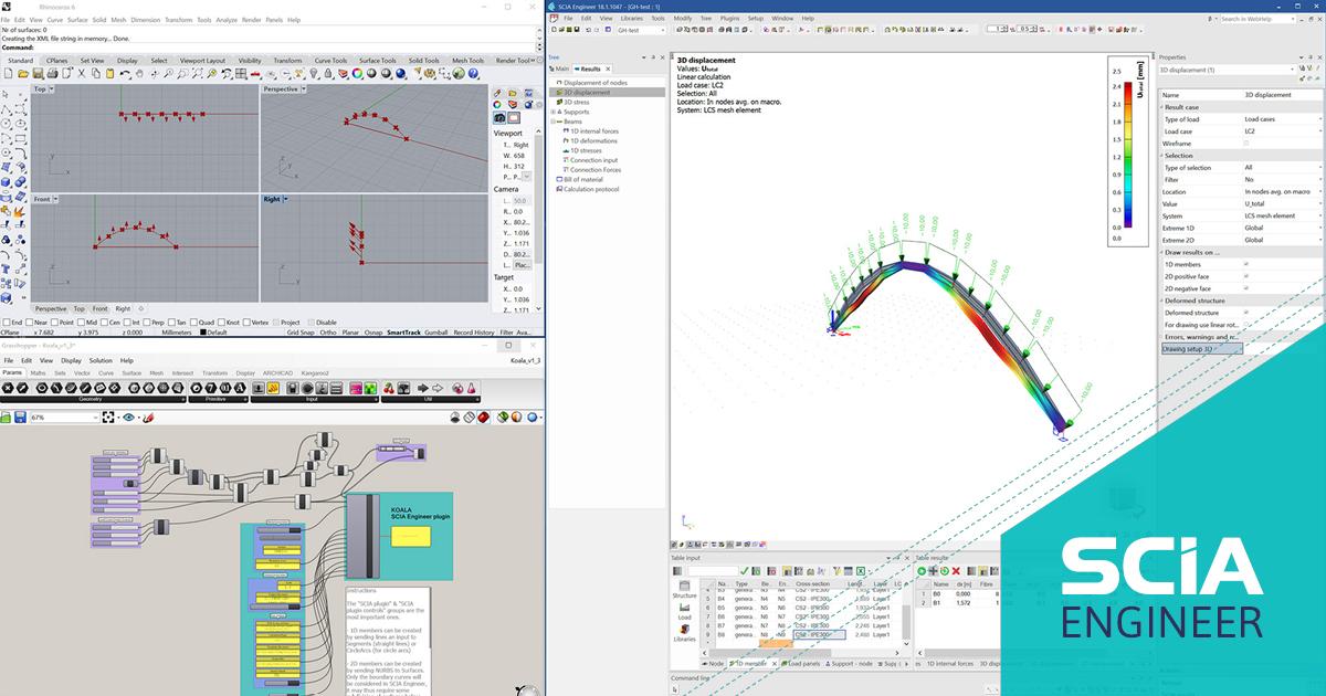
Rhino3D and Grasshopper
An emerging workflow, particularly among high end designers, is utilizing Rhino and Grasshopper to create complex geometry. There is a number of ways that this data can easily be plugged into SCIA Engineer.
- Complex 3D geometries can be imported into SCIA Engineer where they can be easily converted into analytical members, loaded, analyzed and designed.
- Text based output from Rhino can be copied and pasted into SCIA’s tables for automatic model generation. This can be be made more robust with the use of XML.
Try and buy
Buy your SCIA Engineer edition or try it for yourself with a free 30-day software trial.
Request a demo
Discover how our software and services can help you optimize your work and boost your productivity. Request a private demo.